Effective Date of Rule: July 1, 2023.
Purpose: Adoption of the 2021 Washington State Energy Code, Commercial provisions under chapter 51-11C WAC.
Citation of Rules Affected by this Order: New chapter 51-11C WAC, 31 sections; and amending chapter 51-11C WAC, 150 sections.
Adopted under notice filed as WSR 22-02-076 on January 5, 2022.
The second exception was edited for clarity.
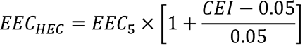
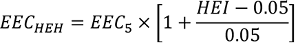
Exception 18 was added based on public testimony that hospitals are required to provide redundant backup systems; it was felt that since the requirement for redundant backup heating applied to both Group I-2 and I-3 occupancies, both should be included in the exception.
A final cost-benefit analysis is available by contacting Stoyan Bumbalov, 1500 Jefferson [Street] S.E., P.O. Box 41449, Olympia, WA 98504-1449, phone 360-407-9277, email Stoyan.bumbalov@des.wa.gov, website sbcc.wa.gov.
Number of Sections Adopted in Order to Comply with Federal Statute: New 0, Amended 0, Repealed 0; Federal Rules or Standards: New 0, Amended 0, Repealed 0; or Recently Enacted State Statutes: New 0, Amended 0, Repealed 0.
Number of Sections Adopted at the Request of a Nongovernmental Entity: New 31, Amended 150, Repealed 0.
Number of Sections Adopted on the Agency's own Initiative: New 0, Amended 0, Repealed 0.
Number of Sections Adopted in Order to Clarify, Streamline, or Reform Agency Procedures: New 0, Amended 0, Repealed 0.
Number of Sections Adopted using Negotiated Rule Making: New 0, Amended 0, Repealed 0; Pilot Rule Making: New 0, Amended 0, Repealed 0; or Other Alternative Rule Making: New 0, Amended 0, Repealed 0.
Date Adopted: April 22, 2022.
C402.2.7 Airspaces. Where the ((thermal properties))R-value of an airspace((s are))is used ((to comply with this code))for compliance in accordance with Section C401.2, ((such))the airspace((s)) shall be enclosed in an unventilated cavity constructed to minimize airflow into and out of the enclosed airspace. Airflow shall be deemed minimized where the enclosed airspace is located on the interior side of the continuous air barrier and is bounded on all sides by building components.
EXCEPTION: | The thermal resistance of airspaces located on the exterior side of the continuous air barrier and adjacent to and behind the exterior wall covering material shall be determined in accordance with ASTM C1363 modified with an airflow entering the bottom and exiting the top of the airspace at a minimum air movement rate of not less than 70 mm/sec. |
AMENDATORY SECTION(Amending WSR 19-24-040, filed 11/26/19, effective 7/1/20)
WAC 51-11C-40228Section C402.2.8—((Insulation of radiant heating systems))Above-grade exterior concrete slabs.
((C402.2.8 Insulation of radiant heating systems.Radiant heating system panels, and their associated components that are installed in interior or exterior assemblies shall be insulated to an R-value of not less than R-3.5 on all surfaces not facing the space being heated. Radiant heating system panels that are installed in the building thermal envelope shall be separated from the exterior of the building or unconditioned or exempt spaces by not less than the R-value of insulation installed in the opaque assembly in which they are installed or the assembly shall comply with Section C402.1.4.
EXCEPTION: | Heated slabs on grade insulated in accordance with Section C402.2.6.)) |
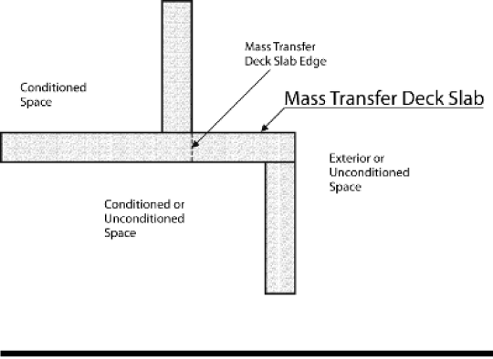
C402.2.8 Above-grade exterior concrete slabs. Above-grade concrete slabs that penetrate the building thermal envelope including, but not limited to, decks and balconies, shall each include a minimum R-10 thermal break, aligned with the primary insulating layer in the adjoining wall assemblies. Stainless steel (but not carbon steel) reinforcing bars are permitted to penetrate the thermal break. If the total building performance path or the component performance alternative in Section C402.1.5 is utilized and the thermal break required by this section is not provided where concrete slabs penetrate the building thermal envelope, the sectional area of the penetration shall be assigned the default U-factors from the "exposed concrete" row of Table A103.3.7.2.
EXCEPTION: | Mass transfer deck slabs. |
NEW SECTION
WAC 51-11C-40229Section C402.2.9—Vertical fenestration intersection with opaque walls.
C402.2.9 Vertical fenestration intersection with opaque walls.Vertical fenestration shall comply with Items 1, 2, and 3, as applicable.
1. Where wall assemblies include continuous insulation, the exterior glazing layer of vertical fenestration and any required thermal break in the frame shall each be aligned within 2 inches laterally of either face of the continuous insulation layer.
2. Where wall assemblies do not include continuous insulation, the exterior glazing layer of vertical fenestration and any required thermal break in the frame shall each be aligned within the thickness of the wall insulation layer and not more than 2 inches laterally from the exterior face of the outermost insulation layer.
3. Where the exterior face of the vertical fenestration frame does not extend to the exterior face of the opaque wall rough opening, the exposed exterior portion of the rough opening shall be covered with either a material having an R-value not less than R-3, or with minimum 1.5-inch thickness wood.
AMENDATORY SECTION(Amending WSR 19-24-040, filed 11/26/19, effective 7/1/20)
WAC 51-11C-40230Section C402.4—Fenestration.
C402.3 Reserved.
C402.4 Fenestration. Fenestration shall comply with Sections C402.4 through C402.4.4 and Table C402.4. Daylight responsive controls shall comply with this section and Section ((C405.2.4.1))C405.2.5.
AMENDATORY SECTION(Amending WSR 19-24-040, filed 11/26/19, effective 7/1/20)
WAC 51-11C-402300Table C402.4—Building envelope requirements—Fenestration.
Table C402.4
Building Envelope Fenestration Maximum U-factor and SHGC Requirements
CLIMATE ZONE | 5 AND MARINE 4 |
U-factor for Class AW windows rated in accordance with AAMA/CSA101/I.S.2/A440, vertical curtain walls and site-built fenestration productsa |
FixedbU-factor | ((U-0.38)) U-0.34 |
OperablecU-factor | ((U-0.40)) U-0.36 |
Entrance doorsd |
U-factor | U-0.60 |
U-factor for all other vertical fenestration |
FixedU-factor | ((U-0.30)) U-0.26 |
Operable or mulled windows with fixed and operable sections U-factor | U-0.28 |
SHGC for all vertical fenestration |
((Orientatione,f)) | ((SEW)) Fixed | ((N)) Operable |
PF < 0.2 | 0.38 | ((0.51)) 0.33 |
0.2 ≤ PF < 0.5 | 0.46 | ((0.56)) 0.40 |
PF ≥ 0.5 | 0.61 | ((0.61)) 0.53 |
Skylights |
U-factor | U-0.50 |
SHGC | 0.35 |
a | U-factor and SHGC shall be rated in accordance with NFRC 100. |
b | "Fixed" includes curtain wall, storefront, picture windows, and other fixed windows. |
c | "Operable" includes openable fenestration products other than "entrance doors." |
d | "Entrance door" includes glazed swinging entrance doors. Other doors which are not entrance doors, including sliding glass doors, are considered "operable." |
e | (("N" indicates vertical fenestration oriented within 30 degrees of true north. "SEW" indicates orientations other than "N."))Reserved. |
f | Fenestration that is entirely within the conditioned space or is between conditioned and other enclosed space is exempt from solar heat gain coefficient requirements and not included in the SHGC calculation. |
AMENDATORY SECTION(Amending WSR 19-24-040, filed 11/26/19, effective 7/1/20)
WAC 51-11C-40231Section C402.4.1—Maximum area.
C402.4.1 Maximum area. The total building vertical fenestration area (not including opaque doors and opaque spandrel panels) shall not exceed 30 percent of the total building gross above-grade wall area. The skylight area shall not exceed 5 percent of the total building gross roof area (skylight-to-roof ratio).
For buildings with more than one space conditioning category, compliance with the maximum allowed window-to-wall ratio and skylight-to-roof ratio shall be demonstrated separately for each space conditioning category. Interior partition ceiling, wall, fenestration and floor areas that separate space conditioning areas shall not be applied to the window-to-wall ratio and skylight-to-roof ratio calculations.
C402.4.1.1 Vertical fenestration maximum area withhigh performance alternates. For buildings that comply with Section C402.4.1.1.1 or C402.4.1.1.2, the total building vertical fenestration area is permitted to exceed 30 percent but shall not exceed 40 percent of the gross above grade wall area for the purpose of prescriptive compliance with Section C402.1.4.
When determining compliance using the component performance alternative in accordance with Section C402.1.5, the total building vertical fenestration area allowed in Equation 4-2 is 40 percent of the above grade wall area for buildings that comply with the vertical fenestration alternates described in this section.
C402.4.1.1.1 Optimized daylighting. All of the following requirements shall be met:
1. Not less than 50 percent of the total conditioned floor area in the building is within a daylight zone that includes daylight responsive controls complying with Section ((C405.2.4.1))C405.2.5.1.
2. Visible transmittance (VT) of all vertical fenestration in the building is greater than or equal to 1.1 times the required solar heat gain coefficient (SHGC) in accordance with Section C402.4, or 0.50, whichever is greater. It shall be permitted to demonstrate compliance based on the area weighted average VT being greater than or equal to the area weighted average of the minimum VT requirements.
EXCEPTION: | Fenestration that is outside the scope of NFRC 200 is not required to comply with Item 2. |
C402.4.1.1.2 High-performance fenestration. All of the following requirements shall be met:
1. All vertical fenestration in the building shall comply with the following U-factors:
a. U-factor for Class AW windows rated in accordance with AAMA/CSA101/I.S.2/A440, vertical curtain walls and site-built fenestration products (fixed) = ((0.34))0.31
b. U-factor for Class AW windows rated in accordance with AAMA/CSA101/I.S.2/A440, vertical curtain walls and site-built fenestration products (operable) = 0.36
c. Entrance doors = 0.60
d. U-factor for all other vertical fenestration, fixed = ((0.28))0.23
e. U-factor for all other vertical fenestration, operable, or mulled windows with fixed and operable sections = 0.24
2. The SHGC of the vertical fenestration shall be ((less than or equal to 0.35, adjusted for projection factor in compliance with C402.4.3))no more than 0.90 times the maximum SHGC values listed in Table C402.4.
An area-weighted average shall be permitted to satisfy the U-factor requirement for each fenestration product category listed in Item 1 of this section. Individual fenestration products from different fenestration product categories shall not be combined in calculating the area-weighted average U-factor, except that fenestration from lines a. and b. are permitted to be combined.
AMENDATORY SECTION(Amending WSR 19-24-040, filed 11/26/19, effective 7/1/20)
WAC 51-11C-40232Section C402.4.2—Minimum skylight fenestration area.
C402.4.2 Minimum skylight fenestration area.((For buildings with single story))Skylights shall be provided in enclosed spaces that meet all the following criteria:
1. Floor area of enclosed spaces is greater than 2,500 square feet (232 m2) ((in floor area that are)).
2. Space is located directly under a roof and have a ceiling height greater than 15 feet (4572 mm) for no less than 75 percent of the ceiling area((, these single-story spaces shall be provided with skylights and daylight responsive controls in accordance with Section C405.2.4)).
3. Space type((s required to comply with this provision include))is one of the following: Office, lobby, atrium, concourse, corridor, gymnasium/exercise center, convention center, automotive service, manufacturing, nonrefrigerated warehouse, retail store, distribution/sorting area, transportation, and workshop.
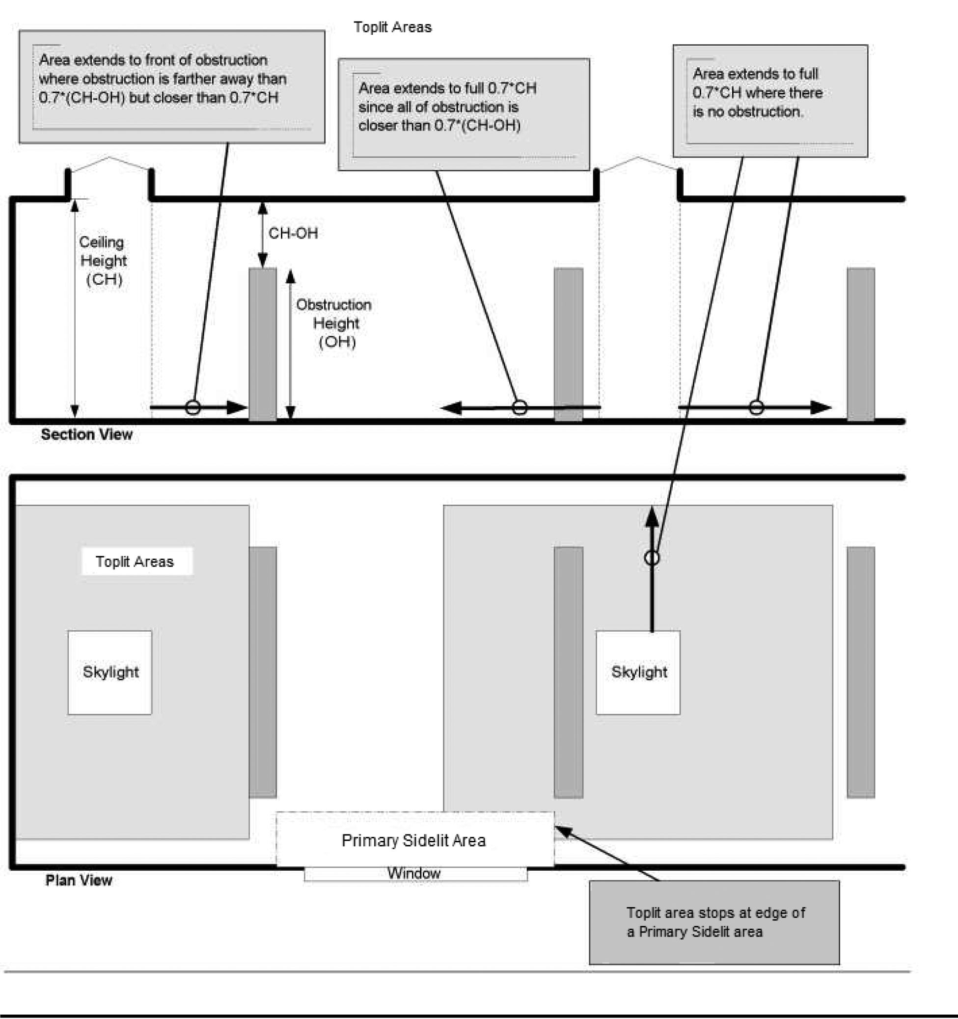
Skylights in these spaces are required to provide a total toplit daylight zone area not less than 50 percent of the floor area and shall provide one of the following:
1. A minimum ratio of skylight area to toplit daylight zone area under skylights of not less than 3 percent where all skylights have a VT of at least 0.40, or VTannual of not less than 0.26, as determined in accordance with Section C303.1.3.
2. A minimum skylight effective aperture ((of at least 1 percent)), determined in accordance with Equation 4-5, of:
2.1. Not less than 1 percent using a skylight's VT rating; or
2.2. Not less than 0.66 percent using a tubular daylight device's VTannual rating.
| Skylight Effective Aperture | = | (0.85 x Skylight Area x Skylight VT x WF)/ Toplit daylight zone | |
(Equation 4-5)
Where: | | |
Skylight area | = | Total fenestration area of skylights. |
Skylight VT | = | Area weighted average visible transmittance of skylights. |
WF | = | Area weighted average well factor, where well factor is 0.9 if light well depth is less than 2 feet (610 mm), or 0.7 if light well depth is 2 feet (610 mm) or greater, or 1.0 for tubular daylighting devices (TDD) with ((VT-annual))VTannual ratings measured in accordance with NFRC 203. |
Light well depth | = | Measure vertically from the underside of the lowest point of the skylight glazing to the ceiling plane under the skylight. |
EXCEPTIONS: | 1. Skylights above daylight zones of enclosed spaces are not required in: |
| 1.1. ((Reserved.))Spaces designed as storm shelters complying with ICC 500. |
| 1.2. Spaces where the designed general lighting power densities are less than 0.5 W/ft2 (5.4 W/m2) and at least 10 percent lower than the lighting power allowance in Section C405.4.2. |
| 1.3. Areas where it is documented that existing structures or natural objects block direct beam sunlight on at least half of the roof over the enclosed area for more than 1,500 daytime hours per year between 8 a.m. and 4 p.m. |
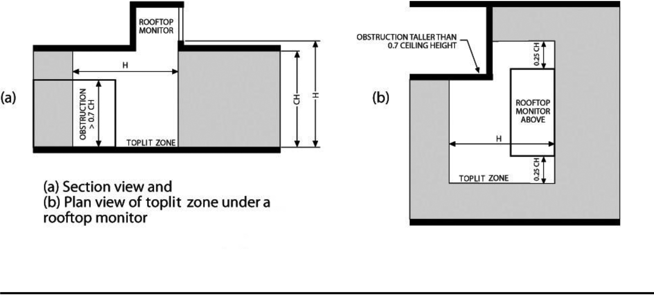
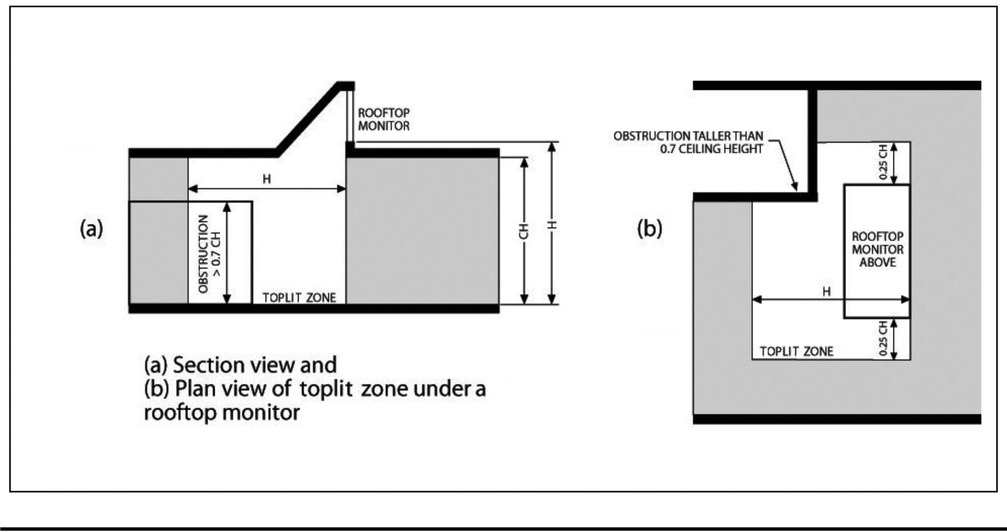
| 1.4. Spaces where the daylight zone under rooftop monitors is greater than 50 percent of the enclosed space floor area. |
| 1.5. Spaces where the total floor area minus the sidelit daylight zone area is less than 2,500 square feet (232 m2), and where the lighting in the daylight zone is controlled in accordance with Section C405.2.3.1. |
| 2. The skylight effective aperture, calculated in accordance with Equation 4-5, is permitted to be 0.66 percent in lieu of 1 percent if the ((VT-annual))VTannual of the skylight or TDD, as measured by NFRC 203, is greater than 38 percent. |
C402.4.2.1 Lighting controls in daylight zones under skylights. Daylight responsive controls ((complying with Section C405.2.4.1)) shall be provided to control all electric lights within toplit daylight zones.
C402.4.2.2 Haze factor. Skylights in office, storage, automotive service, manufacturing, nonrefrigerated warehouse, retail store, and distribution/sorting area spaces shall have a glazing material or diffuser with a haze factor greater than 90 percent when tested in accordance with ASTM D 1003.
EXCEPTION: | Skylights and tubular daylighting devices designed and installed to exclude direct sunlight entering the occupied space by the use of fixed or automated baffles, or the geometry of skylight and light well. |
C402.4.2.3 Daylight zones. Daylight zones referenced in Sections C402.4.1.1 through C402.4.2.2 shall comply with Sections((C405.2.4.2 and C405.2.4.3))C405.2.5.2 and C405.2.5.3, as applicable. Daylight zones shall include toplit daylight zones and sidelit daylight zones.
AMENDATORY SECTION(Amending WSR 19-24-040, filed 11/26/19, effective 7/1/20)
WAC 51-11C-40234Section C402.4.4—Doors.
C402.4.4 Doors. Opaque ((swinging)) doors shall ((comply with Table C402.1.4. Opaque nonswinging doors shall comply with Table C402.1.3. Opaque doors shall)) be considered part of the gross area of above-grade walls that are part of the building thermal envelope, including the frame. Opaque doors shall comply with Table C402.1.4. Other doors shall comply with the provisions of Section C402.4.3 for vertical fenestration ((and the entire door area, including the frame, shall be considered part of the fenestration area of the building thermal envelope)).
AMENDATORY SECTION(Amending WSR 19-24-040, filed 11/26/19, effective 7/1/20)
WAC 51-11C-40241Section C402.5.1—Air barriers.
C402.5.1 Air barriers. A continuous air barrier shall be provided throughout the building thermal envelope. The continuous air barriers shall be ((permitted to be)) located on the inside or outside of the building thermal envelope, located within the assemblies composing the building thermal envelope, or any combination thereof. The air barrier shall comply with Sections C402.5.1.1 and C402.5.1.2.
C402.5.1.1 Air barrier construction. The continuous air barrier shall be constructed to comply with the following:
1. The air barrier shall be continuous for all assemblies that are the thermal envelope of the building and across the joints and assemblies.
2. Air barrier joints and seams shall be sealed, including sealing transitions in places and changes in materials. The joints and seals shall be securely installed in or on the joint for its entire length so as not to dislodge, loosen or otherwise impair its ability to resist positive and negative pressure from wind, stack effect and mechanical ventilation.
3. Penetrations of the air barrier shall be caulked, gasketed or otherwise sealed in a manner compatible with the construction materials and location. Sealing shall allow for expansion, contraction and mechanical vibration. Joints and seams associated with penetrations shall be sealed in the same manner or taped. Sealing materials shall be securely installed around the penetration so as not to dislodge, loosen or otherwise impair the penetrations' ability to resist positive and negative pressure from wind, stack effect, and mechanical ventilation. Sealing of concealed fire sprinklers, where required, shall be in a manner that is recommended by the manufacturer. Caulking or other adhesive sealants shall not be used to fill voids between fire sprinkler cover plates and walls or ceilings.
4. Recessed lighting fixtures shall comply with Section C402.5.8. Where similar objects are installed which penetrate the air barrier, provisions shall be made to maintain the integrity of the air barrier.
5. Construction documents shall contain a diagram showing the building's pressure boundary in plan(s) and section(s) and a calculation of the area of the pressure boundary to be considered in the test.
C402.5.1.2 ((Building test. The completed building shall be tested and the air leakage rate of the building envelope shall not exceed 0.25 cfm/ft2 at a pressure differential of 0.3 inches water gauge (2.0 L/s • m2 at 75 Pa) at the upper 95 percent confidence interval in accordance with ASTM E 779 or an equivalent method approved by the code official. A report that includes the tested surface area, floor area, air by volume, stories above grade, and leakage rates shall be submitted to the building owner and the Code Official. If the tested rate exceeds that defined here by up to 0.15 cfm/ft2, a visual inspection of the air barrier shall be conducted and any leaks noted shall be sealed to the extent practicable. An additional report identifying the corrective actions taken to seal air leaks shall be submitted to the building owner and the Code Official and any further requirement to meet the leakage air rate will be waived. If the tested rate exceeds 0.40 cfm/ft2, corrective actions must be made and the test completed again. A test above 0.40 cfm/ft2 will not be accepted.
1. Test shall be accomplished using either (1) both pressurization and depressurization or (2) pressurization alone, but not depressurization alone. The test results shall be plotted against the corrected P in accordance with Section 9.4 of ASTM E 779.
2. The test pressure range shall be from 25 Pa to 80 Pa per Section 8.10 of ASTM E 779, but the upper limit shall not be less than 50 Pa, and the difference between the upper and lower limit shall not be less than 25 Pa.
3. If the pressure exponent n is less than 0.45 or greater than 0.85 per Section 9.6.4 of ASTM E 779, the test shall be rerun with additional readings over a longer time interval.
C402.5.1.2.1))Air barrier compliance. A continuous air barrier for the opaque building envelope shall comply with the following:
1. Group R dwelling units that are accessed directly from the outdoors shall meet the provisions of Section C402.5.2.
2. All other buildings or portions of buildings shall meet the provisions of Section C402.5.3.
C402.5.2 Enclosure testing for dwelling and sleeping unit accessed directly from the outdoors. For dwelling units accessed directly from outdoors, the building thermal envelope shall be tested in accordance with ASTM E779, ANSI/RESNET/ICC 380, ASTM E1827 or an equivalent method approved by the code official. The measured air leakage shall not exceed 0.25 cfm/ft2 (1.27 L/s m2) of the testing unit enclosure area at a pressure differential of 0.2 inch water gauge (50 Pa). Where multiple dwelling units or sleeping units or other occupiable conditioned spaces are contained within one building thermal envelope and are accessed directly from the outdoors, each unit shall be considered an individual testing unit, and the building air leakage shall be the weighted average of all testing unit results, weighted by each testing unit's enclosure area. Units shall be tested separately with an unguarded blower door test as follows:
1. Where buildings have fewer than eight testing units, each testing unit shall be tested.
2. For buildings with eight or more testing units, the greater of seven units or 20 percent of the testing units in the building shall be tested, including a top floor unit, a ground floor unit and a unit with the largest testing unit enclosure area. For each tested unit that exceeds the maximum air leakage rate, an additional two units shall be tested, including a mixture of testing unit types and locations.
3. Test shall be accomplished using either a) both pressurization and depressurization or b) pressurization alone, but not depressurization alone. The test results shall be plotted against the correct P for pressurization in accordance with Section 9.4 of ASTM E779.
Where the measured air leakage rate exceeds 0.25 cfm/ft2 (2.0 L/s x m2) corrective action shall be taken to seal leaks in the air barrier in all units exceeding the target value and all untested units. Post-corrective action testing and repeated corrective action measures will be taken until the required air leakage rating is achieved. Final passing air leakage test results shall be submitted to the code official.
C402.5.3 Building thermal envelope testing. The building thermal envelope shall be tested in accordance with ASTM E779, ANSI/RESNET/ICC 380, ASTM E3158 or ASTM E1827 or an equivalent method approved by the code official. The measured air leakage shall not exceed 0.25 cfm/ft2 (1.27 L/s × m2) of the building thermal envelope area at a pressure differential of 0.3 inch water gauge (75 Pa). Alternatively, portions of the building shall be tested and the measured air leakages shall be area weighted by the surface areas of the building envelope in each portion. The weighted average test results shall not exceed the whole building leakage limit. In the alternative approach, the following portions of the building shall be tested:
1. The entire envelope area of all stories that have any spaces directly under a roof.
2. The entire envelope area of all stories that have a building entrance, exposed floor, or loading dock, or are below grade.
3. Representative above-grade sections of the building totaling at least 25 percent of the wall area enclosing the remaining conditioned space.
4. Test shall be accomplished using either a) both pressurization and depressurization or b) pressurization alone, but not depressurization alone. The test results shall be plotted against the correct P for pressurization in accordance with Section 9.4 of ASTM E779.
Where the measured air leakage rate exceeds 0.25 cfm/ft2 (2.0 L/s x m2) corrective action shall be taken to seal leaks in the air barrier. Post-corrective action testing and repeated corrective action measures will be taken until the required air leakage rating is achieved. Final passing of the air leakage test results shall be submitted to the code official.
C402.5.4 Building test for mixed-use buildings. Where a building is three or fewer stories above grade plane and contains both commercial and residential uses, the air barrier of the R-2 and R-3 occupancy areas of the building is permitted to be separately tested according to Section R402.4.1.2. Alternatively, it is permissible to test the air barrier of the entire building according to Section ((C402.5.1.2))C402.5.3, provided that the tested air leakage rate does not exceed the rate specified in Section ((C402.5.1.2))C402.5.3.
AMENDATORY SECTION(Amending WSR 19-24-040, filed 11/26/19, effective 7/1/20)
WAC 51-11C-40243Section ((C402.5.3))C402.5.5—Rooms containing fuel-burning appliances.
((C402.5.3))C402.5.5 Rooms containing fuel-burning appliances. Where combustion air is supplied through openings in an exterior wall to a room or space containing a space conditioning fuel-burning appliance, one of the following shall apply:
1. The room or space containing the appliance shall be located outside of the building thermal envelope.
2. The room or space containing the appliance shall be enclosed and isolated from conditioned spaces inside the building thermal envelope. Such rooms shall comply with all of the following:
2.1. The walls, floor and ceiling that separate the enclosed room or space from the conditioned spaces shall be insulated to be at least equivalent to the insulation requirement of below grade walls as specified in Table C402.1.3 or C402.1.4.
2.2. The walls, floors and ceilings that separate the enclosed room or space from conditioned spaces be sealed in accordance with Section C402.5.1.1.
2.3. The doors into the enclosed room or space shall be fully gasketed.
2.4. Water lines and ducts in the enclosed room or space shall be insulated in accordance with Section C403.
2.5. Where the air duct supplying combustion air to the enclosed room or space passes through conditioned space, the duct shall be insulated to an R-value of not less than ((R-8))R-16.
EXCEPTION: | Fireplaces and stoves complying with Sections 901 through 905 of the International Mechanical Code, and Section 2111.13 of the International Building Code. |
AMENDATORY SECTION(Amending WSR 19-24-040, filed 11/26/19, effective 7/1/20)
WAC 51-11C-40244Section ((C402.5.4))C402.5.6—Doors and access openings.
((C402.5.4))C402.5.6 Doors and access openings to shafts, chutes, stairways, and elevator lobbies. Doors and access openings from conditioned space to shafts, chutes, stairways and elevator lobbies shall be gasketed, weatherstripped or sealed.
EXCEPTIONS: | 1. Door openings required to comply with Section 716 of the International Building Code. |
| 2. Doors and door openings required to comply with UL 1784 by the International Building Code. |
AMENDATORY SECTION(Amending WSR 19-24-040, filed 11/26/19, effective 7/1/20)
WAC 51-11C-40245Section ((C402.5.5))C402.5.7—Air intakes, exhaust openings, stairways and shafts.
((C402.5.5))C402.5.7 Air intakes, exhaust openings, stairways and shafts. Stairway enclosures, elevator shaft vents and other outdoor air intakes and exhaust openings integral to the building envelope shall be provided with dampers in accordance with Section ((C403.7.9))C403.7.8.
AMENDATORY SECTION(Amending WSR 19-24-040, filed 11/26/19, effective 7/1/20)
WAC 51-11C-40246Section ((C402.5.6))C402.5.8—Loading dock weatherseals.
((C402.5.6))C402.5.8 Loading dock weatherseals. Cargo door openings and loading dock door openings shall be equipped with weatherseals that restrict infiltration and provide direct contact along the top and sides of vehicles that are parked in the doorway.
AMENDATORY SECTION(Amending WSR 19-24-040, filed 11/26/19, effective 7/1/20)
WAC 51-11C-40247Section ((C402.5.7))C402.5.9—Vestibules.
((C402.5.7))C402.5.9 Vestibules. All building entrances shall be protected with an enclosed vestibule, with all doors opening into and out of the vestibule equipped with self-closing devices. Vestibules shall be designed so that in passing through the vestibule it is not necessary for the interior and exterior doors to open at the same time. The installation of one or more revolving doors in the building entrance shall not eliminate the requirement that a vestibule be provided on any doors adjacent to revolving doors. For the purposes of this section, "building entrances" shall include exit-only doors in buildings where separate doors for entering and exiting are provided.
Interior and exterior doors shall have a minimum distance between them of not less than 7 feet. The exterior envelope of conditioned vestibules shall comply with the requirements for a conditioned space. Either the interior or exterior envelope of unconditioned vestibules shall comply with the requirements for a conditioned space. The building lobby is not considered a vestibule.
EXCEPTION: | Vestibules are not required for the following: |
| 1. Doors not intended to be used as building entrances. |
| 2. Unfinished ground-level space greater than 3,000 square feet (298 m2) if a note is included on the permit documents at each exterior entrance to the space stating "Vestibule required at time of tenant build-out if entrance serves a space greater than 3,000 square feet in area." |
| 3. Doors opening directly from a sleeping unit or dwelling unit. |
| 4. Doors between an enclosed space smaller than 3,000 square feet (298 m2) in area and the exterior of the building or the building entrance lobby, where those doors do not comprise one of the primary building entrance paths to the remainder of the building. The space must be enclosed and separated without transfer air paths from the primary building entrance paths. If there are doors between the space and the primary entrance path, then the doors shall be equipped with self-closing devices so the space acts as a vestibule for the primary building entrance. |
| 5. Revolving doors. |
| 6. Doors used primarily to facilitate vehicular movement or material handling and adjacent personnel doors. |
| 7. In buildings less than 3 stories above grade or in spaces that do not directly connect with the building elevator lobby, doors that have an air curtain with a velocity of not less than 6.56 feet per second (2 m/s) at the floor that have been tested in accordance with ANSI/AMCA 220 and installed in accordance with the manufacturer's instructions. Manual or automatic controls shall be provided that will operate the air curtain with the opening and closing of the door. Air curtains and their controls shall comply with Section C408.2.3. |
| 8. Building entrances in buildings that are less than four stories above grade and less than 10,000 ft2 in area. |
| 9. Elevator doors in parking garages provided that the elevators have an enclosed lobby at each level of the garage. |
| 10. Entrances to semi-heated spaces. |
| 11. Doors that are used only to access outdoor seating areas that are separated from adjacent walking areas by a fence or other barrier. |
AMENDATORY SECTION(Amending WSR 16-03-072, filed 1/19/16, effective 7/1/16)
WAC 51-11C-40248Section ((C402.5.8))C402.5.10—Recessed lighting.
((C402.5.8))C402.5.10 Recessed lighting. Recessed luminaires installed in the building thermal envelope shall be all of the following:
1. IC rated.
2. Labeled as having an air leakage rate of not more than 2.0 cfm (0.944 L/s) when tested in accordance with ASTM E 283 at a 1.57 psf (75 Pa) pressure differential.
3. Sealed with a gasket or caulk between the housing and interior wall or ceiling covering.
C402.5.11 Operable openings interlocking. Where any operable openings to the outdoors are larger than 48 square feet (4.47 m2) in area, such openings shall be interlocked with the heating and cooling system as required by Section C403.4.1.6.
EXCEPTIONS: | 1. Separately zoned areas associated with the preparation of food that contain appliances that contribute to the HVAC loads of a restaurant or similar type of occupancy. |
| 2. Warehouses that utilize overhead doors for the function of the occupancy, where approved by the code official. |
| 3. The outer entrance doors where located in the exterior wall and are part of a vestibule system. |
| 4. Alterations to existing buildings. |
AMENDATORY SECTION(Amending WSR 20-21-080, filed 10/19/20, effective 2/1/21)
WAC 51-11C-40310Section C403.1—General.
C403.1 General. Mechanical systems and equipment serving heating, cooling, ventilating, and other needs shall comply with this section.
EXCEPTIONS: | 1. Energy using equipment used by a manufacturing, industrial or commercial process other than for conditioning spaces or maintaining comfort and amenities for the occupants ((and not otherwise regulated by))are exempt from all Section C403 subsections except for Section C403.3.2, Tables C403.3.2 (1) through (((12)))(16) inclusive, Sections C403.3.4.1, C403.3.4.2, C403.3.4.3, C403.7.7, C403.9.2.1, C403.10.3, C403.11.2, and C403.11.3, ((C404.2, Table C404.2, C405.8 and C410))as applicable. Data center and computer room HVAC equipment is not covered by this exception. |
| 2. Data center systems are exempt from Sections C403.4 and C403.5. |
C403.1.1 HVAC total system performance ratio (HVAC TSPR). For systems serving office (including medical office), retail, library, and education occupancies and buildings, which are subject to the requirements of Section C403.3.5 without exceptions, and the dwelling units and residential common areas within Group R-2 multi-family buildings, the HVAC total system performance ratio (HVAC TSPR) of the proposed design HVAC system shall be ((more))greater than or equal to the HVAC TSPR of the standard reference design as calculated according to Appendix D, Calculation of HVAC Total System Performance Ratio.
EXCEPTIONS: | 1. Buildings ((with conditioned floor area less than 5,000 square feet))where the sum of the conditioned floor area of office, retail, education, library and multifamily spaces is less than 5,000 square feet. Areas that are eligible for any of the exceptions below do not count towards the 5,000 square feet. |
| 2. HVAC systems using district heating water, chilled water or steam. |
| 3. HVAC systems connected to a low-carbon district energy exchange system. |
| 4. HVAC systems not included in Table ((D601.11.1))D601.10.1. |
| ((4.))5. HVAC systems with chilled water supplied by absorption chillers, heat recovery chillers, water to water heat pumps, air to water heat pumps, or a combination of air and water cooled chillers on the same chilled water loop. |
| 6. HVAC systems included in Table D601.10.1 with parameters in Table D601.10.2 not identified as applicable to that HVAC system type. |
| ((5.))7. HVAC systems served by heating water plants that include air to water or water to water heat pumps. |
| ((6.))8. Underfloor air distribution and displacement ventilation HVAC systems. |
| ((7.))9. Space conditioning systems that do not include mechanical cooling. |
| ((8.))10. Alterations to existing buildings that do not substantially replace the entire HVAC system and are not serving initial build-out construction. |
| ((9.))11. HVAC systems meeting all the requirements of the standard reference design HVAC system in Table D602.11, Standard Reference Design HVAC Systems. |
| 12. Buildings or areas of medical office buildings that comply fully with ASHRAE Standard 170 including, but not limited to, surgical centers, or that are required by other applicable codes or standards to provide 24/7 air handling unit operation. |
| 13. HVAC systems serving the following areas and spaces: |
| 13.1. Laundry rooms. |
| 13.2. Elevator machine rooms. |
| 13.3. Mechanical and electrical rooms. |
| 13.4. Data centers and computer rooms. |
| 13.5. Laboratories with fume hoods. |
| 13.6. Locker rooms with more than two showers. |
| 13.7. Natatoriums and rooms with saunas. |
| 13.8. Restaurants and commercial kitchens with total cooking capacity greater than 100,000 Btu/h. |
| 13.9. Areas of buildings with commercial refrigeration equipment exceeding 100 kW of power input. |
| 13.10. Cafeterias and dining rooms. |
C403.1.2 Calculation of heating and cooling loads. Design loads associated with heating, ventilating and air conditioning of the building shall be determined in accordance with the procedures described in ANSI/ASHRAE/ACCA Standard 183 or by an approved equivalent computational procedure, using the design parameters specified in Chapter 3. Heating and cooling loads shall be adjusted to account for load reductions that are achieved where energy recovery systems are utilized in the HVAC system in accordance with the ASHRAE HVAC Systems and Equipment Handbook by an approved equivalent computational procedure.
C403.1.3 Data centers.Data center systems shall comply with Sections 6 and 8 of ASHRAE Standard 90.4 ((with the following changes:
1. Replace design MLC in ASHRAE Standard 90.4 Table 6.2.1.1 "Maximum Design Mechanical Load Component (Design MLC)" with the following per the applicable climate zone:
Zone 4C Design MLC = 0.22 Zone 5B Design MLC = 0.24
2. Replace annualized MLC values of Table 6.2.1.2 "Maximum Annualized Mechanical Load Component (Annualized MLC)" in ASHRAE Standard 90.4 with the following per applicable climate zone:
Zone 4C Annual MLC = 0.18 Zone 5B Annual MLC = 0.17)).
NEW SECTION
WAC 51-11C-40314Section C403.1.4—HVAC heating equipment.
C403.1.4 Use of electric resistance and fossil fuel-fired HVAC heating equipment. HVAC heating energy shall not be provided by electric resistance or fossil fuel combustion appliances. For the purposes of this section, electric resistance HVAC heating appliances include, but are not limited to, electric baseboard, electric resistance fan coil and VAV electric resistance terminal reheat units and electric resistance boilers. For the purposes of this section, fossil fuel combustion HVAC heating appliances include, but are not limited to, appliances burning natural gas, heating oil, propane, or other fossil fuels.
EXCEPTIONS: | 1. Low heating capacity. Buildings or areas of buildings, other than dwelling units or sleeping units, that meet the interior temperature requirements of Chapter 12 of the International Building Code with a total installed HVAC heating capacity no greater than 8.5 Btu/h (2.5 watts) per square foot of conditioned space are permitted to be heated using electric resistance appliances. |
| 2. Dwelling and sleeping units. Dwelling or sleeping units are permitted to be heated using electric resistance appliances as long as the installed HVAC heating capacity in any separate space is not greater than: |
| 2.1. Seven hundred fifty watts in Climate Zone 4, and 1000 watts in Climate Zone 5 in each habitable space with fenestration. |
| 2.2. One thousand watts in Climate Zone 4, and 1300 watts in Climate Zone 5 for each habitable space that has two primary walls facing different cardinal directions, each with exterior fenestration. Bay windows and other minor offsets are not considered primary walls. |
| 2.3. Two hundred fifty watts in spaces adjoining the building thermal envelope but without fenestration. |
| For the purposes of this section, habitable space is as defined in the International Building Code. For buildings in locations with exterior design conditions below 4°F (-16°C), an additional 250 watts above that allowed for Climate Zone 5 is permitted in each space with fenestration. |
| 3. Small buildings. Buildings with less than 2,500 square feet (232 m2) of conditioned floor area are permitted to be heated using electric resistance appliances. |
| 4. Defrost. Heat pumps are permitted to utilize electric resistance heating when a heat pump defrost cycle is required and is in operation. |
| 5. Air-to-air heat pumps. Buildings are permitted to utilize internal electric resistance heaters to supplement heat pump heating for air-to-air heat pumps that meet all of the following conditions: |
| 5.1. Internal electric resistance heaters have controls that prevent supplemental heater operation when the heating load can be met by the heat pump alone during both steady-state operation and setback recovery. |
| 5.2. The heat pump controls are configured to use the compressor as the first stage of heating down to an outdoor air temperature of 17°F (-8°C) or lower except when in defrost. |
| 5.3. The heat pump complies with one of the following: |
| 5.3.1. Controlled by a digital or electronic thermostat designed for heat pump use that energizes the supplemental heat only when the heat pump has insufficient capacity to maintain set point or to warm up the space at a sufficient rate. |
| 5.3.2. Controlled by a multistage space thermostat and an outdoor air thermostat wired to energize supplemental heat only on the last stage of the space thermostat and when outdoor air temperature is less than 32°F (0°C) except when in defrost. |
| 5.3.3. The minimum efficiency of the heat pump is regulated by NAECA, its rating meets the requirements shown in Table C403.3.2(2), and its rating includes all usage of internal electric resistance heating. |
| 5.4. The heat pump rated heating capacity is sized to meet the heating load at an outdoor air temperature of 32°F (0°C) or lower and has a rated heating capacity at 47°F (8°C) no less than 2 times greater than supplemental internal electric resistance heating capacity in Climate Zone 4 and no less than the supplemental internal electric resistance heating capacity in Climate Zone 5, or utilizes the smallest available factory-available internal electric resistance heater. |
| 6. Air-to-water heat pumps. Buildings are permitted to utilize electric resistance (for Climate Zone 4 or 5) or fossil fuel-fired (for Climate Zone 5) auxiliary heating to supplement heat pump heating for hydronic heating systems that meet all of the following conditions: |
| 6.1. Controls for the auxiliary electric resistance or fossil fuel-fired heating are configured to lock out the supplemental heat when the outside air temperature is above 36°F (2°C), unless the hot water supply temperature setpoint to the building heat coils cannot be maintained for 20 minutes. |
| 6.2. The heat pump controls are configured to use the compressor as the first stage of heating down to the lowest exterior design temperature for which the equipment is rated except during startup or defrost operation. |
| 6.3. The heat pump rated heating capacity at 47°F (8°C) is no less than 75 percent of the design heating load at 29°F (-2°C). |
| 7. Ground source heat pumps. Buildings are permitted to utilize electric resistance auxiliary heating to supplement heat pump heating for hydronic heating systems with ground source heat pump equipment that meets all of the following conditions: |
| 7.1. Controls for the auxiliary resistance heating are configured to lock out the supplemental heat when the equipment source-side entering water temperature is above 42°F (6°C), unless the hot water supply temperature setpoint to the building heat coils cannot be maintained for 20 minutes. |
| 7.2. The heat pump controls are configured to use the compressor as the first stage of heating. |
| 7.3. The ground source heat exchanger shall be sized so that the heat pump annual heating output is no less than 70 percent of the total annual heating output in the final year of a 30-year simulation using IGSHPA listed simulation software. |
| 8. Small systems. Buildings in which electric resistance or fossil fuel appliances, including decorative appliances, either provide less than 5 percent of the total building HVAC system heating capacity or serve less than 5 percent of the conditioned floor area. |
| 9. Specific conditions. Portions of buildings that require fossil fuel or electric resistance space heating for specific conditions approved by the code official for research, health care, process or other specific needs that cannot practicably be served by heat pump or other space heating systems. This does not constitute a blanket exception for any occupancy type. |
| 10. Kitchen make-up air. Make-up air for commercial kitchen exhaust systems required to be tempered by Section 508.1.1 of the International Mechanical Code is permitted to be heated by using fossil fuel in Climate Zone 5 or electric resistance in Climate Zone 4 or 5. |
| 11. District energy. Steam or hot water district energy systems that utilize fossil fuels as their primary source of heat energy, that serve multiple buildings, and that were already in existence prior to the effective date of this code, including more energy-efficient upgrades to such existing systems, are permitted to serve as the primary heating energy source. |
| 12. Heat tape. Heat tape is permitted where it protects water-filled equipment and piping located outside of the building thermal envelope, provided that it is configured and controlled to be automatically turned off when the outside air temperature is above 40°F (4°C). |
| 13. Temporary systems. Temporary electric resistance heating systems are permitted where serving future tenant spaces that are unfinished and unoccupied, provided that the heating equipment is sized and controlled to achieve interior space temperatures no higher than 40°F (4°C). |
| 14. Pasteurization. Electric resistance heat controls are permitted to reset the supply water temperature of hydronic heating systems that serve service water heating heat exchangers during pasteurization cycles of the service hot water storage volume. The hydronic heating system supply water temperature shall be configured to be 145°F (63°C) or lower during the pasteurization cycle. |
| 15. Freeze protection. Heating systems sized for spaces with indoor design conditions of 45°F (7°C) and intended for freeze protection are permitted to use electric resistance. The building envelope of any such space shall be insulated in compliance with Section C402.1. |
| 16. DOAS ERV auxiliary heat. Dedicated outdoor air systems with energy recovery ventilation are permitted to utilize fossil fuel for Climate Zone 5 or electric resistance in Climate Zone 4 or 5 for auxiliary heating to preheat outdoor air for defrost or as auxiliary supplemental heat to temper supply air to 55°F (13°C) or lower for buildings or portions of buildings that do not have hydronic heating systems. |
| 17. Low-carbon district energy systems. Low-carbon district energy systems that meet the definitions of low-carbon district energy exchange system or low-carbon district heating and cooling or heating only systems. |
| 18. Essential facilities. Groups I-2 and I-3 occupancies that by regulation are required to have in place redundant emergency backup systems. |
AMENDATORY SECTION(Amending WSR 19-24-040, filed 11/26/19, effective 7/1/20)
WAC 51-11C-40320Section C403.2—System design.
C403.2 System design. Mechanical systems shall be designed to comply with Sections C403.2.1 and ((C403.2.2))C403.2.4. Where elements of a building's mechanical systems are addressed in Sections C403.3 through C403.13, such elements shall comply with the applicable provisions of those sections.
AMENDATORY SECTION(Amending WSR 19-24-040, filed 11/26/19, effective 7/1/20)
WAC 51-11C-40321Section C403.2.1—Zone isolation.
C403.2.1Zone isolation required. HVAC systems, DOAS and exhaust systems serving ((zones))areas that are intended to operate or be occupied nonsimultaneously shall be divided into separate isolation areas. Zones intended to be occupied simultaneously may be grouped into a single isolation area provided ((it))the combined total area does not exceed 25,000 square feet (2323 m2) of conditioned floor area ((nor))and does not include more than one floor. Each isolation area shall be equipped with isolation devices and controls configured to automatically shut off the supply of conditioned air and outdoor air to and exhaust air from the isolation area. Each isolation area shall be controlled independently by a device meeting the requirements of Section C403.4.2.2. Central systems and plants shall be provided with controls and devices that will allow system and equipment operation for any length of time while serving only the smallest isolation area served by the system or plant.
EXCEPTIONS: | 1. Exhaust air and outdoor air connections to isolation areas where the fan system to which they connect is not greater than 5,000 cfm (2360 L/s). |
| 2. Exhaust airflow from a single isolation area of less than 10 percent of the design airflow of the exhaust system to which it connects. |
| 3. Isolation areas intended to operate continuously or intended to be inoperative only when all other isolation areas in a zone are inoperative. |
AMENDATORY SECTION(Amending WSR 19-24-040, filed 11/26/19, effective 7/1/20)
WAC 51-11C-40322Section C403.2.2—Ventilation and exhaust.
C403.2.2 Ventilation and exhaust.
C403.2.2.1 Ventilation. Ventilation, either natural or mechanical, shall be provided in accordance with Chapter 4 of the International Mechanical Code. Where mechanical ventilation is provided, the system shall be configured to provide no greater than 150 percent of the minimum outdoor air required by Chapter 4 of the International Mechanical Code or other applicable code or standard, whichever is greater.
EXCEPTIONS: | 1. The mechanical system may supply outdoor air at rates higher than the limit above when it is used for particulate or VOC dilution, ((economizer,))economizing or night flushing, dehumidification, pressurization, exhaust make-up, or other process air delivery. Outdoor air shall be reduced to the minimum ventilation rates when not required for the preceding uses. |
| 2. Air systems supplying dwelling or sleeping units within Group R-1, R-2 or I-2 occupancies. |
| 3. Alterations that replace less than half of the total heating and cooling capacity of the system. |
| 4. Systems with energy recovery complying with the requirements of Section C403.7.6.1 that utilize sensible only active chilled beams for space cooling without any additional zonal fan power. Active chilled beams shall be permitted to utilize the increased outdoor airflow to increase space sensible capacity and to maintain space latent cooling loads without additional controls to reduce the outdoor airflow to each zone. |
| 5. Systems that include energy recovery ventilation with an 80 percent minimum sensible recovery effectiveness in accordance with Section C403.3.5.1 and with controls capable and configured to lock-out the use of supplemental heat may provide ventilation up to a maximum of 200 percent of the minimum outdoor air required. |
C403.2.2.2 Exhaust. Exhaust shall be provided in accordance with Chapters 4 and 5 of the International Mechanical Code. Where exhaust is provided, the system shall be configured to provide no greater than 150 percent of the minimum exhaust air required by Chapters 4 and 5 of the International Mechanical Code or other applicable code or standard, whichever is greater.
EXCEPTIONS: | 1. The mechanical system may exhaust air at rates higher than the limit above when it is used for particulate or VOC dilution, economizer, night flushing, dehumidification, pressure equalization, relief, or other process exhaust air requirements. Outdoor air and exhaust air shall be reduced to the minimum ventilation rates when not required for the preceding uses. |
| 2. Domestic range hood exhaust in Group R occupancies. |
| 3. Exhaust from Group I occupancies. |
AMENDATORY SECTION(Amending WSR 19-24-040, filed 11/26/19, effective 7/1/20)
WAC 51-11C-40323Section C403.2.3—((Variable flow capacity))Fault detection and diagnostics.
((C403.2.3 Variable flow capacity. For fan and pump motors 7.5 hp and greater including motors in or serving custom and packaged air handlers serving variable air volume fan systems, constant volume fans, heating and cooling hydronic pumping systems, pool and service water pumping systems, domestic water pressure-booster systems, cooling tower fan, and other pump or fan motors where variable flows are required, there shall be:
1. Variable speed drives; or
2. Other controls and devices that will result in fan and pump motor demand of no more than 30 percent of design wattage at 50 percent of design air volume for fans when static pressure set point equals 1/3 the total design static pressure, and 50 percent of design water flow for pumps, based on manufacturer's certified test data. Variable inlet vanes, throttling valves (dampers), scroll dampers or bypass circuits shall not be allowed.
EXCEPTION: | Variable speed devices are not required for motors that serve: |
| 1. Fans or pumps in packaged equipment where variable speed drives are not available as a factory option from the equipment manufacturer. |
| 2. Fans or pumps that are required to operate only for emergency fire-life-safety events (e.g., stairwell pressurization fans, elevator pressurization fans, fire pumps, etc.).)) |
C403.2.3 Fault detection and diagnostics. New buildings with an HVAC system serving a gross conditioned floor area of 100,000 square feet (9290 m2) or larger shall include a fault detection and diagnostics (FDD) system to monitor the HVAC system's performance and automatically identify faults. The FDD system shall:
1. Include permanently installed sensors and devices to monitor the HVAC system's performance.
2. Sample the HVAC system's performance at least once every 15 minutes.
3. Automatically identify and report HVAC system faults.
4. Automatically notify authorized personnel of identified HVAC system faults.
5. Automatically provide prioritized recommendations for repair of identified faults based on analysis of data collected from the sampling of HVAC system performance.
6. Be capable of transmitting the prioritized fault repair recommendations to remotely located authorized personnel.
EXCEPTION: | Group R-1 and R-2 occupancies. |
AMENDATORY SECTION(Amending WSR 19-24-040, filed 11/26/19, effective 7/1/20)
WAC 51-11C-40324((Reserved.))Section C403.2.4—Variable flow capacity.
C403.2.4 Variable flow capacity. For fan and pump motors 5.0 hp and greater including motors in or serving custom and packaged air handlers serving variable air volume fan systems, constant volume fans, heating and cooling hydronic pumping systems, pool and service water pumping systems, domestic water pressure-booster systems, cooling tower fan, and other pump or fan motors where variable flows are required, there shall be:
1. Variable speed drives; or
2. Other controls and devices that will result in fan and pump motor demand of no more than 30 percent of design wattage at 50 percent of design air volume for fans when static pressure set point equals 1/3 the total design static pressure, and 50 percent of design water flow for pumps, based on manufacturer's certified test data. Variable inlet vanes, throttling valves (dampers), scroll dampers or bypass circuits shall not be allowed.
EXCEPTION: | Variable speed devices are not required for motors that serve: |
| 1. Fans or pumps in packaged equipment where variable speed drives are not available as a factory option from the equipment manufacturer. |
| 2. Fans or pumps that are required to operate only for emergency fire-life-safety events (e.g., stairwell pressurization fans, elevator pressurization fans, fire pumps, etc.). |
AMENDATORY SECTION(Amending WSR 19-24-040, filed 11/26/19, effective 7/1/20)
WAC 51-11C-40332Section C403.3.2—HVAC equipment performance requirements.
C403.3.2 HVAC equipment performance requirements. Equipment shall meet the minimum efficiency requirements of Tables C403.3.2(1) through C403.3.2(((12)))(16) when tested and rated in accordance with the applicable test procedure. Plate-type liquid-to-liquid heat exchangers shall meet the minimum requirements of ((Table C403.3.2(10)))AHRI 400. The efficiency shall be verified through certification and listed under an approved certification program or, if no certification program exists, the equipment efficiency ratings shall be supported by data furnished by the manufacturer. Where multiple rating conditions or performance requirements are provided, the equipment shall satisfy all stated requirements. Where components, such as indoor or outdoor coils, from different manufacturers are used, calculations and supporting data shall be furnished by the designer that demonstrates that the combined efficiency of the specified components meets the requirements herein.
C403.3.2.1 Gas-fired and oil-fired forced air furnaces. Forced air furnaces with input ratings ≥ 225,000 Btu/h (65 kW) and all unit heaters shall also have an intermittent ignition or interrupted device (IID), and have either mechanical draft (including power venting) or a flue damper. A vent damper is an acceptable alternative to a flue damper for furnaces where combustion air is drawn from the conditioned space. All furnaces with input ratings ≥ 225,000 Btu/h (65 kW), including electric furnaces, that are not located within the conditioned space shall have jacket losses not exceeding 0.75 percent of the input rating.
((C403.3.2.1))C403.3.2.2 Hydronic and multiple-zone HVAC system controls and equipment. Hydronic and multiple-zone HVAC system controls and equipment shall comply with this section.
For buildings with a total equipment cooling capacity of 300 tons and above, the equipment shall comply with one of the following:
1. No one unit shall have a cooling capacity of more than 2/3 of the total installed cooling equipment capacity;
2. The equipment shall have a variable speed drive; or
3. The equipment shall have multiple compressors.
C403.3.2.3 Chillers. Chilled water plants and buildings with more than 500 tons total capacity shall not have more than 100 tons provided by air-cooled chillers.
EXCEPTIONS: | 1. Where the designer demonstrates that the water quality at the building site fails to meet manufacturer's specifications for the use of water-cooled equipment. |
| 2. Air-cooled chillers with minimum efficiencies at least 10 percent higher than those listed in Table ((C403.3.2(7)))C403.3.2(3). |
| 3. Replacement of existing air-cooled chiller equipment. |
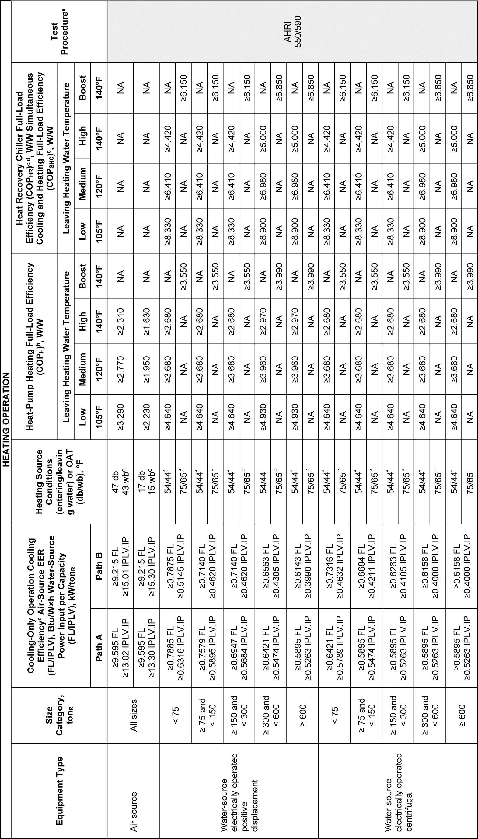
| 4. Air-to-water heat pump units that are configured to provide both heating and cooling and that are rated in accordance with AHRI 550/590. ((Where the air-to-water heat pumps are designed for a maximum supply leaving water temperature of less than 140°F, the efficiency rating will be calculated and reported at the maximum unit leaving water temperature for this test condition.)) |
((C403.3.2.2))C403.3.2.4 Water-cooled centrifugal chilling packages. Equipment not designed for operation at AHRI Standard 550/590 test conditions of ((44°F (7°C)))44.00°F (6.67°C) leaving and 54.00°F (12.22°C) entering chilled-water temperatures and ((2.4 gpm/ton evaporator fluid flow and 85°F (29°C) entering condenser water temperature with 3 gpm/ton (0.054 L/s • kW) condenser water flow))with 85.00°F (29.44°C) entering and 94.30°F (34.61°C) leaving condenser-fluid temperatures, shall have maximum full-load kW/ton (FL) and part-load ratings adjusted using ((Equations 4-7 and 4-8))the following equations.
(Equation 4-7)
(Equation 4-8)
Where: | |
Kadj | = | A × B |
FL | = | Full-load kW/ton values as specified in Table C403.3.2(7) |
FLadj | = | Maximum full-load kW/ton rating, adjusted for nonstandard conditions |
IPLV.IP | = | Value as specified in Table C403.3.2(7) |
PLVadj | = | Maximum NPLV rating, adjusted for nonstandard conditions |
A | = | 0.00000014592 × (LIFT)4 - 0.0000346496 × (LIFT)3+ 0.00314196 × (LIFT)2 - 0.147199 × LIFT + ((3.9302))3.93073 |
B | = | 0.0015 × LvgEvap (° F) + 0.934 |
LIFT | = | LvgCond - LvgEvap |
LvgCond | = | Full-load condenser leaving fluid temperature (°F) |
LvgEvap | = | Full-load evaporator leaving temperature (°F) |
The FLadj and PLVadj values are ((only)) applicable only for centrifugal chillers meeting all of the following full-load design ranges:
((1. Minimum evaporator leaving temperature: 36°F.
2. Maximum condenser leaving temperature: 115°F.
3. LIFT is not less than 20°F (11.1°C) and not greater than 80°F (44.4°C)))• 36.00°F ≤ LvgEvap ≤ 60.00°F
• LvgCond ≤ 115.00°F
• 20.00°F ≤ LIFT ≤ 80.00°F
Manufacturers shall calculate the FLadj and PLVadjbefore determining whether to label the chiller. Centrifugal chillers designed to operate outside of these ranges are not covered by this code.
((C403.3.2.3))C403.3.2.5 Positive displacement (air- and water-cooled) chilling packages. Equipment with a leaving fluid temperature higher than 32°F (0°C) and water-cooled positive displacement chilling packages with a condenser leaving fluid temperature below 115°F (46°C) shall meet the requirements ((of Table C403.3.2(7)))the tables in Section C403.3.2 when tested or certified with water at standard rating conditions, in accordance with the referenced test procedure.
((C403.3.2.4))C403.3.2.6 Packaged and split system electric heating and cooling equipment. Packaged ((electric))and split system equipment providing both electric heating and cooling, and cooling-only equipment with electric heat in the main supply duct before VAV boxes, in each case with a total cooling capacity greater than 6,000 Btu/h shall be a heat pump configured to operate in heat pump mode whenever the outdoor air temperature is above 25°F (-3.9°C) and the unit is not in defrost. The unit shall have reverse-cycle demand defrost.
EXCEPTION: | Unstaffed equipment shelters or cabinets used solely for personal wireless service facilities. |
((C403.3.2.5))C403.3.2.7 Humidification. If an air economizer is required on a cooling system for which humidification equipment is to be provided to maintain minimum indoor humidity levels, then the humidifier shall be of the adiabatic type (direct evaporative media or fog atomization type).
EXCEPTIONS: | 1. Health care facilities licensed by the state where chapter 246-320 or 246-330 WAC requires steam injection humidifiers in duct work downstream of final filters. |
| 2. Systems with water economizer. |
| 3. 100 percent outside air systems with no provisions for air recirculation to the central supply fan. |
| 4. Nonadiabatic humidifiers cumulatively serving no more than 10 percent of a building's air economizer capacity as measured in cfm. This refers to the system cfm serving rooms with stand alone or duct mounted humidifiers. |
OTS-3534.2
NEW SECTION
WAC 51-11C-403321Table C403.3.2(1)—Electrically operated unitary air conditioners and condensing units.
Table C403.3.2(1)
Minimum Efficiency Requirements—Electrically Operated Unitary Air Conditioners and Condensing Unitsc,d
Equipment Type | Size Category | Heating Section Type | Subcategory or Rating Condition | Minimum Efficiency | Test Procedurea |
Air conditioners, air cooled | < 65,000 Btu/hb | All | Split System, three phase and applications outside U.S. single phaseb | 13.4 SEER2 | AHRI 201/240-2023 |
Single package, three phase and applications outside U.S. single phaseb | 13.4 SEER2 |
Space constrained, air cooled | ≤ 30,000 Btu/hb | All | Split System, three phase and applications outside U.S. single phaseb | 11.7 SEER2 |
Single package, three phase and applications outside U.S. single phaseb | 11.7 SEER2 |
Small duct high velocity, air cooled | ≤ 65,000 Btu/hb | All | Split System, three phase and applications outside U.S. single phaseb | 12.1 SEER2 |
Air conditioners, air cooled | ≥ 65,000 Btu/h and < 135,000 Btu/h | Electric Resistance (or None) | Split System and Single Package | 11.2 EER 14.8 IEER | AHRI 340/360 |
All other | Split System and Single Package | 11.0 EER 14.6 IEER |
≥ 135,000 Btu/h and < 240,000 Btu/h | Electric Resistance (or None) | Split System and Single Package | 11.0 EER 14.2 IEER |
All other | Split System and Single Package | 10.8 EER 14.0 IEER |
≥ 240,000 Btu/h and < 760,000 Btu/h | Electric Resistance (or None) | Split System and Single Package | 10.0 EER 13.2 IEER |
All other | Split System and Single Package | 9.8 EER 13.0 IEER |
≥ 760,000 Btu/h | Electric Resistance (or None) | Split System and Single Package | 9.7 EER 12.5 IEER |
All other | Split System and Single Package | 9.5 EER 12.3 IEER |
Air conditioners, water cooled | < 65,000 Btu/hb | All | Split System and Single Package | 12.1 EER 12.3 IEER | AHRI 210/240 |
≥ 65,000 Btu/h and < 135,000 Btu/h | Electric Resistance (or None) | Split System and Single Package | 12.1 EER 13.9 IEER | AHRI 340/360 |
All other | Split System and Single Package | 11.9 EER 13.7 IEER |
≥ 135,000 Btu/h and < 240,000 Btu/h | Electric Resistance (or None) | Split System and Single Package | 12.5 EER 13.9 IEER |
All other | Split System and Single Package | 12.3 EER 13.7 IEER |
≥ 240,000 Btu/h and < 760,000 Btu/h | Electric Resistance (or None) | Split System and Single Package | 12.4 EER 13.6 IEER |
All other | Split System and Single Package | 12.2 EER 13.4 IEER |
≥ 760,000 Btu/h | Electric Resistance (or None) | Split System and Single Package | 12.2 EER 13.5 IEER |
All other | Split System and Single Package | 12.0 EER 13.3 IEER |
Air conditioners, evaporatively cooled | < 65,000 Btu/hb | All | Split System and Single Package | 12.1 EER 12.3 IEER | AHRI 210/240 |
≥ 65,000 Btu/h and < 135,000 Btu/h | Electric Resistance (or None) | Split System and Single Package | 12.1 EER 12.3 IEER | AHRI 340/360 |
All other | Split System and Single Package | 11.9 EER 12.1 IEER |
≥ 135,000 Btu/h and < 240,000 Btu/h | Electric Resistance (or None) | Split System and Single Package | 12.0 EER 12.2 IEER |
All other | Split System and Single Package | 11.8 EER 12.0 IEER |
≥ 240,000 Btu/h and < 760,000 Btu/h | Electric Resistance (or None) | Split System and Single Package | 11.9 EER 12.1 IEER |
All other | Split System and Single Package | 11.7 EER 11.9 IEER |
≥ 760,000 Btu/h | Electric Resistance (or None) | Split System and Single Package | 11.7 EER 11.9 EER |
All other | Split System and Single Package | 11.5 EER 11.7 EER |
Condensing units, air cooled | ≥ 135,000 Btu/h | | | 10.5 EER 11.8 IEER | AHRI 365 |
Condensing units, water cooled | ≥ 135,000 Btu/h | | | 13.5 EER 14.0 IEER |
Condensing units, evaporatively cooled | ≥ 135,000 Btu/h | | | 13.5 EER 14.0 IEER |
For SI: 1 British thermal unit per hour = 0.2931 W. |
| a | Chapter 6 contains a complete specification of the referenced standards, which include test procedures, including the reference year version of the test procedure. |
| b | Single-phase, U.S. air-cooled air conditioners less than 65,000 Btu/h are regulated as consumer products by the U.S. Department of Energy Code of Federal Regulations DOE 10 C.F.R. 430. SEER and SEER2 values for single-phase products are set by the U.S. Department of Energy. |
| c | DOE 10 C.F.R. 430 Subpart B Appendix MI includes the test procedure updates effective 1/1/2023 that will be incorporated in AHRI 210/240-2023. |
| d | This table is a replica of ASHRAE 90.1 Table 6.8.1-1 Electrically Operated Unitary Air Conditioners and Condensing Units—Minimum Efficiency Requirements. |
NEW SECTION
WAC 51-11C-403322Table C403.3.2(2)—Electrically operated air-cooled unitary heat pumps—Minimum efficiency requirements.
Table C403.3.2(2)
Electrically Operated Air-Cooled Unitary Heat Pumps—Minimum Efficiency Requirements
Equipment Type | Size Category | Heating Section Type | Subcategory or Rating Condition | Minimum Efficiency | Test Procedurea |
Air cooled
(cooling mode)
| < 65,000 Btu/h | All | Split System, three phase and applications outside U.S. single phaseb | 14.3 SEER2 | AHRI 201/240-2023 |
Single Package, three phase and applications outside U.S. single phaseb | 13.4 SEER2 |
Space constrained, air cooled | ≤ 30,000 Btu/h | All | Split System, three phase and applications outside U.S. single phaseb | 11.7 SEER2 |
Single Package, three phase and applications outside U.S. single phaseb | 11.7 SEER2 |
Single duct high velocity, air cooled (cooling mode) | ≤ 65,000 Btu/h | All | Split System, three phase and applications outside U.S. single phaseb | 12.0 SEER2 |
Air cooled (cooling mode) | ≥ 65,000 Btu/h and < 135,000 Btu/h | Electric Resistance (or None) | Split System and Single Package | 11.0 EER 14.1 IEER | AHRI 340/360 |
All other | Split System and Single Package | 10.8 EER 13.9 IEER |
≥ 135,000 Btu/h and < 240,000 Btu/h | Electric Resistance (or None) | Split System and Single Package | 10.6 EER 13.5 IEER |
All other | Split System and Single Package | 10.4 EER 13.3 IEER |
≥ 240,000 Btu/h | Electric Resistance (or None) | Split System and Single Package | 9.5 EER 12.5 IEER |
All other | Split System and Single Package | 9.3 EER 12.3 IEER |
Air cooled (heating mode) | < 65,000 Btu/hb | - | Split System, three phase and applications outside U.S. single phaseb | 7.5 HSPF | AHRI 201/240-2023 |
- | Single Package, three phase and applications outside U.S. single phaseb | 6.7 HSPF |
Space constrained, air cooled (heating mode) | ≤ 30,000 Btu/h | - | Split System, three phase and applications outside U.S. single phaseb | 6.3 HSPF |
- | Single Package, three phase and applications outside U.S. single phaseb | 6.3 HSPF |
Small-duct high velocity air cooled (heating mode)
| < 65,000 Btu/h | - | Split System, three phase and applications outside U.S. single phaseb | 6.1 HSPF |
Air cooled (heating mode) | ≥ 65,000 Btu/h and < 135,000 Btu/h (cooling capacity) | - | 47ºF db/43ºF wb Outdoor Air | 3.40 COPH | AHRI 340/360 |
17ºF db/15ºF wb Outdoor Air | 2.25 COPH |
≥ 135,000 Btu/h and < 240,000 Btu/h (cooling capacity) | - | 47ºF db/43ºF wb Outdoor Air | 3.30 COPH |
17ºF db/15ºF wb Outdoor Air | 2.05 COPH |
≥ 240,000 Btu/h (cooling capacity) | | 47ºF db/43ºF wb Outdoor Air | 3.20 COPH |
| 17ºF db/15ºF wb Outdoor Air | 2.05 COPH |
For SI: 1 British thermal unit per hour = 0.2931 W, °C = [(°F) - 32]/1.8. |
| a | Chapter 6 contains a complete specification of the referenced standards, which include test procedures, including the reference year version of the test procedure. |
| b | Single-phase, U.S. air-cooled heat pumps less than 65,000 Btu/h are regulated as consumer products by the U.S. Department of Energy Code of Federal Regulations DOE 10 C.F.R. 430. SEER, SEER2, and HSPF values for single-phase products are set by the U.S. Department of Energy. |
| c | DOE 10 C.F.R. 430 Subpart B Appendix MI includes the test procedure updates effective 1/1/2023 that will be incorporated into AHRI 210/240-2023. |
| d | This table is a replica of ASHRAE 90.1 Table 6.8.1-2 Electrically Operated Air-Cooled Unitary Heat Pumps—Minimum Efficiency Requirements. |
NEW SECTION
WAC 51-11C-403323Table C403.3.2(3)—Water chilling packages—Minimum efficiency requirements.
Table C403.3.2(3)
Water Chilling Packages—Minimum Efficiency Requirementsa,b,e,f
| Size Category | | Path A | Path B | Test Procedurec |
Equipment Type | Units | FL | IPLV,IP | FL | IPLV,IP |
Air-cooled chillers | < 150 tons | EER(Btu/Wh) | ≥ 10.100 | ≥ 13.700 | ≥ 9.700 | ≥ 15.800 | |
≥ 150 tons | EER(Btu/Wh) | ≥ 10.100 | ≥ 14.000 | ≥ 9.700 | ≥ 16.100 | |
Air cooled without condenser, electrically operated | All capacities | EER(Btu/Wh) | Air-cooled chillers without condensers shall be rated with matching condensers and comply with the air-cooled chiller efficiency requirements | |
Water cooled, electrically operated, positive displacement | < 75 tons | kW/ton | ≤ 0.750 | ≤ 0.600 | ≤ 0.780 | ≤ 0.500 | |
≥ 75 tons and < 150 tons | kW/ton | ≤ 0.720 | ≤ 0.560 | ≤ 0.750 | ≤ 0.490 | AHRI 550/590 |
≥ 150 tons and < 300 tons | kW/ton | ≤ 0.660 | ≤ 0.540 | ≤ 0.680 | ≤ 0.440 | |
≥ 300 tons and < 600 tons | kW/ton | ≤ 0.610 | ≤ 0.520 | ≤ 0.625 | ≤ 0.410 | |
| ≥ 600 tons | kW/ton | ≤ 0.560 | ≤ 0.500 | ≤ 0.585 | ≤ 0.380 | |
Water cooled, electrically operated, centrifugal | < 150 tons | kW/ton | ≤ 0.610 | ≤ 0.550 | ≤ 0.695 | ≤ 0.440 | |
≥ 150 tons and < 300 tons | kW/ton | ≤ 0.610 | ≤ 0.550 | ≤ 0.695 | ≤ 0.400 | |
≥ 300 tons and < 400 tons | kW/ton | ≤ 0.560 | ≤ 0.520 | ≤ 0.595 | ≤ 0.390 | |
≥ 400 tons and < 600 tons | kW/ton | ≤ 0.560 | ≤ 0.500 | ≤ 0.585 | ≤ 0.380 | |
≥ 600 tons | kW/ton | ≤ 0.560 | ≤ 0.500 | ≤ 0.585 | ≤ 0.380 | |
Air cooled absorption, single effect | All capacities | COP(W/W) | ≥ 0.600 | NR | NAd | NAd | |
Water cooled absorption, single effect | All capacities | COP(W/W) | ≥ 0.700 | NR | NAd | NAd | AHRI 560 |
Absorption double effect, indirect fired | All capacities | COP(W/W) | ≥ 1.000 | ≥ 1.050 | NAd | NAd |
Absorption double effect, direct fired | All capacities | COP(W/W) | ≥ 1.000 | ≥ 1.000 | NAd | NAd | |
For SI: 1 ton = 3517 W, 1 British thermal unit per hour = 0.2931 W, °C = [(°F) - 32]/1.8. |
| NR = No requirement. |
| a | Chapter 6 contains a complete specification of the referenced standards, which includes test procedures, including the referenced year version of the test procedure. |
| b | The requirements for centrifugal chiller shall be adjusted for nonstandard rating conditions per Section C403.3.2.4 and are applicable only for the range of conditions listed there. The requirements for air-cooled, water-cooled positive displacement and absorption chillers are at standard rating conditions defined in the referenced test procedure. |
| c | Both the full load and IPLV.IP requirements must be met or exceeded to comply with this standard. When there is a Path B, compliance can be with either Path A or Path B for any application. |
| d | NA means the requirements are not applicable for Path B and only Path A can be used for compliance. |
| e | FL is the full-load performance requirements, and IPLV.IP is for the part-load performance requirements. |
| f | This table is a replica of ASHRAE 90.1 Table 6.8.1-3 Water-Chilling Packages—Minimum Efficiency Requirements. |
NEW SECTION
WAC 51-11C-403324Table C403.3.2(4)—Minimum efficiency requirements—Electrically operated PTAC, PTHP, SPVAC, SPVHP, room air conditioners.
Table C403.3.2(4)
Electrically Operated Packaged Terminal Air Conditioners, Packaged Terminal Heat Pumps, Single-Package Vertical Air Conditioners, Single-Package Vertical Heat Pumps, Room Air Conditioners and Room Air-Conditioner Heat Pumps—Minimum Efficiency Requirementse
Equipment Type | Size Category (Input) | Subcategory or Rating Condition | Minimum Efficiency | Test Procedurea |
PTAC (cooling mode) Standard size | < 7,000 Btu/h | 95°F db/75°F wb outdoor airc | 11.9 EER | AHRI 310/380 |
≥ 7,000 Btu/h and ≤ 15,000 Btu/h | 14.0 - (0.300 × Cap/1000) EERd |
> 15,000 Btu/h | 9.5 EER |
PTAC (cooling mode) Nonstandard sizea | < 7,000 Btu/h | 95°F db/75°F wb outdoor airc | 9.4 EER | AHRI 310/380 |
≥ 7,000 Btu/h and ≤ 15,000 Btu/h | 10.9 - (0.213 × Cap/1000) EERd |
> 15,000 Btu/h | 7.7 EER |
PTHP (cooling mode) Standard size | < 7,000 Btu/h | 95°F db/75°F wb outdoor airc | 11.9 EER | AHRI 310/380 |
≥ 7,000 Btu/h and ≤ 15,000 Btu/h | 14.0 - (0.300 × Cap/1000) EERd |
> 15,000 Btu/h | 9.5 EER |
PTHP (cooling mode) Nonstandard sizeb | < 7,000 Btu/h | 95°F db/75°F wb outdoor airc | 9.3 EER | AHRI 310/380 |
≥ 7,000 Btu/h and ≤ 15,000 Btu/h | 10.8 - (0.213 × Cap/1000) EERd |
> 15,000 Btu/h | 7.6 EER |
PTHP (heating mode) Standard size | < 7,000 Btu/h | 47°F db/43°F wb outdoor air | 3.3 COPH | AHRI 310/380 |
≥ 7,000 Btu/h and ≤ 15,000 Btu/h | 3.7 - (0.052 × Cap/1000) COPHd |
> 15,000 Btu/h | 2.90 COPH |
PTHP (heating mode) Nonstandard sizeb | < 7,000 Btu/h | 47°F db/43°F wb outdoor air | 2.7 COPH | AHRI 310/380 |
≥ 7,000 Btu/h and ≤ 15,000 Btu/h | 2.9 - (0.026 × Cap/1000) COPHd |
> 15,000 Btu/h | 2.5 COPH |
SPVAC (cooling mode) | < 65,000 Btu/h | 95°F db/75°F wb outdoor airc | 11.0 EER | AHRI 390 |
≥ 65,000 Btu/h and < 135,000 Btu/h | 10.0 EER |
≥ 135,000 Btu/h and < 240,000 Btu/h | 10.0 EER |
SPVHP (cooling mode) | < 65,000 Btu/h | 95°F db/75°F wb outdoor airc | 11.0 EER | AHRI 390 |
≥ 65,000 Btu/h and < 135,000 Btu/h | 10.0 EER |
≥ 135,000 Btu/h and < 240,000 Btu/h | 10.0 EER |
SPVHP (heating mode) | <65,000 Btu/h | 47°F db/43°F wb outdoor air | 3.3 COP | AHRI 390 |
≥ 65,000 Btu/h and < 135,000 Btu/h | 3.0 COP |
≥ 135,000 Btu/h and < 240,000 Btu/h | 3.0 COP |
Room air conditioners without reverse cycle with louvered sides for applications outside U.S. | < 6,000 Btu/h | - | 11.0 CEER | ANSI/AHAMRAC-1 |
≥ 6,000 Btu/h and < 8,000 Btu/h | - | 11.0 CEER |
≥ 8,000 Btu/h and < 14,000 Btu/h | - | 10.9 CEER |
≥ 14,000 Btu/h and < 20,000 Btu/h | - | 10.7 CEER |
≥ 20,000 Btu/h and < 28,000 Btu/h | - | 9.4 CEER |
≥ 28,000 Btu/h | - | 9.0 CEER |
Room air conditioners without louvered sides | < 6,000 Btu/h | - | 10.0 CEER | ANSI/AHAMRAC-1 |
≥ 6,000 Btu/h and < 8,000 Btu/h | - | 10.0 CEER |
≥ 8,000 Btu/h and < 11,000 Btu/h | - | 9.6 CEER |
≥ 11,000 Btu/h and < 14,000 Btu/h | - | 9.5 CEER |
≥ 14,000 Btu/h and < 20,000 Btu/h | - | 9.3 CEER |
≥ 20,000 Btu/h | - | 9.4 CEER |
Room air conditioners with reverse cycle, with louvered sides for applications outside U.S. | < 20,000 Btu/h | - | 9.8 CEER | ANSI/AHAMRAC-1 |
≥ 20,000 Btu/h | - | 9.3 CEER |
Room air conditioners with reverse cycle without louvered sides for applications outside U.S. | < 14,000 Btu/h | - | 9.3 CEER | ANSI/AHAMRAC-1 |
≥ 14,000 Btu/h | - | 8.7 CEER |
Room air conditioners, casement only for applications outside U.S. | All capacities | - | 9.5 CEER | ANSI/AHAMRAC-1 |
Room air conditioners, casement-slider for application outside U.S. | All capacities | - | 10.4 CEER | ANSI/AHAMRAC-1 |
For SI: 1 British thermal unit per hour = 0.2931 W, °C = [(°F) - 32]/1.8. |
| | "Cap" = The rated cooling capacity of the product in Btu/h. If the unit's capacity is less than 7,000 Btu/h, use 7,000 Btu/h in the calculation. If the unit's capacity is greater than 15,000 Btu/h, use 15,000 Btu/h in the calculations. |
| a | Chapter 6 contains a complete specification of the referenced standards, which include test procedures, including the referenced year version of the test procedure. |
| b | Nonstandard size units must be factory labeled as follows: "MANUFACTURED FOR NONSTANDARD SIZE APPLICATIONS ONLY: NOT TO BE INSTALLED IN NEW STANDARD PROJECTS." Nonstandard size efficiencies apply only to units being installed in existing sleeves having an external wall opening of less than 16 inches (406 mm) high or less than 42 inches (1067 mm) wide and having a cross-sectional area less than 670 square inches (0.43 m2). |
| c | The cooling-mode wet bulb temperature requirement only applies for units that reject condensate to the condenser coil. |
| d | "Cap" in EER and COPH equations for PTACs and PTHPs means cooling capacity in Btu/h at 95°F outdoor dry-bulb temperature. |
| e | This table is a replica of ASHRAE 90.1 Table 6.8.1-4 Electrically Operated Packaged Terminal Air Conditioners, Packaged Terminal Heat Pumps, Single-Package Vertical Air Conditioners, Single-Package Vertical Heat Pumps, Room Air Conditioners, and Room Air-Conditioner Heat Pumps—Minimum Efficiency Requirements. |
NEW SECTION
WAC 51-11C-403325Table C403.3.2(5)—Minimum efficiency requirements—Warm air furnaces and unit heaters.
Table C403.3.2(5)
Warm Air Furnaces and Combination Warm Air Furnaces/Air-Conditioning Units, Warm Air Duct Furnaces and Unit Heaters—Minimum Efficiency Requirements
Equipment Type | Size Category (Input) | Subcategory or Rating Condition | Minimum Efficiencyd,c | Test Procedurea |
Warm-air furnace, gas fired for application outside the U.S. | < 225,000 Btu/h | Maximum capacityc | 80% AFUE (nonweatherized) or 1% AFUE (weatherized) or 80% Etb,d | DOE 10 C.F.R. 430 Appendix N or Section 2.39, Thermal Efficiency, ANSI Z21.47 |
Warm-air furnace, gas fired | < 225,000 Btu/h | Maximum capacityc | 80% Etb,d before 1/1/2023 81% Etd after 1/1/2023 | Section 2.39, Thermal Efficiency, ANSI Z21.47 |
Warm-air furnace, oil fired | < 225,000 Btu/h | Maximum capacityc | 83% AFUE (nonweatherized) or 78% AFUE (weatherized) or 80% Etb,d | DOE 10 C.F.R. 430 Appendix N or Section 42, Combustion UL 727 |
Warm-air furnace, oil fired | < 225,000 Btu/h | Maximum capacityc | 80% Et before 1/1/2023 82% Etd after 1/1/2023 | Section 42, Combustion UL 727 |
Electric furnaces for applications outside the U.S. | < 225,000 Btu/h | All | 96% AFUE | DOE 10 C.F.R. 430 Appendix N |
Warm air duct furnaces, gas fired | All capacities | Maximum capacityc | 80% Ece | Section 2.10, Efficiency, ANSI Z83.8 |
Warm air unit heaters, gas fired | All capacities | Maximum capacityc | 80% Ece,f | Section 2.10, Efficiency, ANSI Z83.8 |
Warm air unit heaters, oil fired | All capacities | Maximum capacityc | 80% Ece,f | Section 40, Combustion, UL 731 |
For SI: 1 British thermal unit per hour = 0.2931 W. |
| a | Chapter 6 contains a complete specification of the referenced standards, which include test procedures, including the referenced year version of the test procedure. |
| b | Combination units (i.e., furnaces contained within the same cabinet as an air conditioner) not covered by DOE 10 C.F.R. 430 (i.e., 3-phase power or with cooling capacity greater than or equal to 65,000 Btu/h) may comply with either rating. All other units greater than 225,000 Btu/h sold in the U.S. must meet the AFUE standards for consumer products and testing using U.S. DOE's AFUE test procedure at DOE 10 C.F.R. 430 Subpart B, Appendix N. |
| c | Compliance of multiple firing rate units shall be at the maximum firing rate. |
| d | Et | = | Thermal efficiency. Units must also include an interrupted or intermittent ignition device (IID), have jacket losses not exceeding 0.75 percent of the input rating, and have either power venting or a flue damper. A vent damper is an acceptable alternative to a flue damper for those furnaces where combustion air is drawn from the conditioned space. |
| e | Ec | = | Combustion efficiency (100% less flue losses). See test procedure for detailed discussion. |
| f | Units must also include an interrupted or intermittent ignition device (IID) and have either power venting or an automatic flue damper. |
| g | This table is a replica of ASHRAE 90.1 Table 6.8.1-5 Warm-Air Furnaces and Combination Warm-Air Furnaces/Air-Conditioning Units, Warm-Air Duct Furnaces, and Unit Heaters—Minimum Efficiency Requirements. |
NEW SECTION
WAC 51-11C-403326Table C403.3.2(6)—Minimum efficiency requirements—Gas-fired and oil-fired boilers.
Table C403.3.2(6)
Gas- and Oil-Fired Boilers—Minimum Efficiency Requirements
Equipment Typea | Subcategory or Rating Condition | Size Category (Input) | Minimum Efficiency | Test Procedurea |
Boilers, hot water | Gas-fired | < 300,000 Btu/hg,h for applications outside the U.S. | 82% AFUE | DOE 10 C.F.R. 430 Appendix N |
≥ 300,000 Btu/h and ≤ 2,500,000 Btu/he | 84% Etd | DOE 10 C.F.R. 431.86 |
> 2,500,000 Btu/h and ≤ 10,000,000 Btu/hb | 85% Etd |
> 10,000,000 Btu/hb | 82% Ecc |
Oil-firedf | < 300,000 Btu/hg,h | 84% AFUE | DOE 10 C.F.R. 430 Appendix N |
≥ 300,000 Btu/h and ≤ 2,500,000 Btu/he | 87% Etd | DOE 10 C.F.R. 431.86 |
> 2,500,000 Btu/hb | 88% Ecc |
> 10,000,000 Btu/hb | 84% Ecd |
Boilers, steam | Gas-fired | < 300,000 Btu/hg | 81% AFUE | DOE 10 C.F.R. 430 Appendix N |
Gas-fired - all, except natural draft | ≥ 300,000 Btu/h and ≤ 2,500,000 Btu/hb | 82% Etd | DOE 10 C.F.R. 431.86 |
> 2,500,000 Btu/ha | 79% Etd |
> 10,000,000 Btu/hb | 79% Etd |
Gas-fired - natural draft | ≥ 300,000 Btu/h and ≤ 2,500,000 Btu/hb | 81% Etd |
> 2,500,000 Btu/hb | 82% Etd |
> 10,000,000 Btu/hb | 79% Etd |
Oil-firedf | < 300,000 Btu/h | 82% AFUE | DOE 10 C.F.R. 430 Appendix N |
≥ 300,000 Btu/h and ≤ 2,500,000 Btu/hb | 84% Etd | DOE 10 C.F.R. 431.86 |
> 2,500,000 Btu/hb | 85% Etd |
> 10,000,000 Btu/hb | 81% Etd |
For SI: 1 British thermal unit per hour = 0.2931 W. |
| a | Chapter 6 contains a complete specification of the referenced standards, which include test procedures, including the reference year version of the test procedure. |
| b | These requirements apply to boilers with rated input of 8,000,000 Btu/h or less that are not packaged boilers and to all packaged boilers. Minimum efficiency requirements for boilers cover all capacities of packaged boilers. |
| c | Ec | = | Combustion efficiency (100 percent less flue losses). |
| d | Et | = | Thermal efficiency. |
| e | Maximum capacity – Minimum and maximum ratings as provided for and allowed by the unit's controls. |
| f | Includes oil-fired (residual). |
| g | Boilers shall not be equipped with a constant burning pilot light. |
| h | A boiler not equipped with a tankless domestic water heating coil shall be equipped with an automatic means for adjusting the temperature of the water such that an incremental change in inferred heat load produces a corresponding incremental change in the temperature of the water supplied. |
| i | This table is a replica of ASHRAE 90.1 Table 6.8.1-6 Gas- and Oil-Fired Boilers—Minimum Efficiency Requirements. |
NEW SECTION
WAC 51-11C-403327Table C403.3.2(7)—Heat rejection equipment—Minimum efficiency requirements.
Table C403.3.2(7)
Heat Rejection Equipment—Minimum Efficiency Requirementsi
Equipment Typea | Total System Heat Rejection Capacity at Rated Conditions | Subcategory or Rating Conditionh | Performance Requiredb,c,d,f,g | Test Procedurea,e |
Propeller or axial fan open-circuit cooling towers | All | 95°F Entering Water 85°F Leaving Water 75°F Entering wb | ≥ 40.2 gpm/hp | CTI ATC-105 and CTI STD-201 RS |
Centrifugal fan open circuit cooling towers | All | 95°F Entering Water 85°F Leaving Water 75°F Entering wb | ≥ 20.0 gpm/hp | CTI ATC-105 and CTI STD-201 RS |
Propeller or axial fan closed-circuit cooling towers | All | 102°F Entering Water 90°F Leaving Water 75°F Entering wb | ≥ 16.1 gpm/hp | CTI ATC-105S and CTI STD-201 RS |
Centrifugal closed-circuit cooling towers | All | 102°F Entering Water 90°F Leaving Water 75°F Entering wb | ≥ 7.0 gpm/hp | CTI ATC-105S and CTI STD-201 RS |
Propeller or axial fan dry coolers (air-cooled fluid coolers) | All | 115°F Entering Water 105°F Leaving Water 95°F Entering wb | ≥ 4.5 gpm/hp | CTI ATC-106 |
Propeller or axial fan evaporative condensers | All | R-448A Test Fluid 165°F Entering Gas Temperature 105°F Condensing Temperature 75°F Entering wb | ≥ 160,000 Btu/h • hp | CTI ATC-106 |
Propeller or axial fan evaporative condensers | All | Ammonia Test Fluid 140°F Entering Gas Temperature 96.3°F Condensing Temperature 75°F Entering wb | ≥ 134,000 Btu/h • hp | CTI ATC-106 |
Centrifugal fan evaporative condensers | All | R-448A Test Fluid 165°F Entering Gas Temperature 105°F Condensing Temperature 75°F Entering wb | ≥ 137,000 Btu/h • hp | CTI ATC-106 |
Centrifugal fan evaporative condensers | All | Ammonia Test Fluid 140°F Entering Gas Temperature 96.3°F Condensing Temperature 75°F Entering wb | ≥ 110,000 Btu/h • hp | CTI ATC-106 |
Air cooled condensers | All | 125°F Condensing Temperature R-22 Test Fluid 190°F Entering Gas Temperature 15°F Subcooling 95°F Entering db | ≥ 176,000 Btu/h • hp | AHRI 460 |
For SI: °C = [(°F) - 32]/1.8, L/s • kW = (gpm/hp)/(11.83), COP = (Btu/h • hp)/(2550.7). |
| db = dry-bulb temperature, °F. |
| wb = wet-bulb temperature, °F. |
a | Chapter 6 contains a complete specification of the referenced standards, which include test procedures, including the reference year version of the test procedure. |
b | For purposes of this table, open-circuit cooling tower performance is defined as the water-flow rating of the tower at the thermal rating condition listed in the table divided by the fan motor nameplate power. |
c | For purposes of this table, closed-circuit cooling tower performance is defined as the water-flow rating of the tower at the thermal rating condition divided by the sum of the fan motor nameplate power and the integral spray pump motor nameplate power. |
d | For purposes of this table, dry-cooler performance is defined as the process water-flow rating of the unit at the thermal rating condition listed in the table divided by the total fan motor nameplate power of the unit, and air-cooled condenser performance is defined as the heat rejected from the refrigerant divided by the total fan motor nameplate power of the unit. |
e | The efficiencies and test procedures for both open- and closed-circuit cooling towers are not applicable to hybrid cooling towers that contain a combination of separate wet and dry heat exchange sections. The certification requirements do not apply to field-erected cooling towers. |
f | All cooling towers shall comply with the minimum efficiency listed in the table for that specific type of tower with the capacity effect of any project-specific accessories and/or options included in the capacity of the cooling tower. |
g | For purposes of this table, evaporative condenser performance is defined as the heat rejected at the specified rating condition in the table, divided by the sum of the fan motor nameplate power and the integral spray pump nameplate power. |
h | Requirements for evaporative condensers are listed with ammonia (R-717) and R-448A as test fluids in the table. Evaporative condensers intended for use with halocarbon refrigerants other than R-448A must meet the minimum efficiency requirements listed above with R-448A as the test fluid. For ammonia, the condensing temperature is defined as the saturation temperature corresponding to the refrigerant pressure at the condenser entrance. For R-448A, which is a zeotropic refrigerant, the condensing temperature is defined as the arithmetic average of the dew point and the bubble point temperatures corresponding to the refrigerant pressure at the condenser entrance. |
i | This table is a replica of ASHRAE 90.1 Table 6.8.1-7 Performance Requirements for Heat Rejection Equipment—Minimum Efficiency Requirements. |
NEW SECTION
WAC 51-11C-403328Table C403.3.2(8)—Electrically operated variable refrigerant flow air conditioners—Minimum efficiency requirements.
Table C403.3.2(8)
Electrically Operated Variable Refrigerant Flow Air Conditioners—Minimum Efficiency Requirementsb
Equipment Type | Size Category | Heating Section Type | Subcategory or Rating Condition | Minimum Efficiency | Test Procedurea |
| < 65,000 Btu/h | All | VRF Multi-Split System | 13.0 SEER | |
VRF Air Conditioners, Air Cooled | ≥ 65,000 Btu/h and < 135,000 Btu/h | Electric Resistance (or none) | VRF Multi-Split System | 11.2 EER 15.5 IEER | AHRI 1230 |
| ≥ 135,000 Btu/h and < 240,000 Btu/h | Electric Resistance (or none) | VRF Multi-Split System | 11.0 EER 14.9 IEER | |
| ≥ 240,000 Btu/h | Electric Resistance (or none) | VRF Multi-Split System | 10.0 EER 13.9 IEER | |
For SI: 1 British thermal unit per hour = 0.2931 W. |
a | Chapter 6 contains a complete specification of the referenced standards, which include test procedures, including the reference year version of the test procedure. |
b | This table is a replica of ASHRAE 90.1 Table 6.8.1-8 Electrically Operated Variable-Refrigerant-Flow Air Conditioners—Minimum Efficiency Requirements. |
NEW SECTION
WAC 51-11C-403329Tables C403.3.2(9) through C403.3.2(16)—HVAC equipment minimum efficiency requirements.
Table C403.3.2(9)
Electrically Operated Variable Refrigerant Flow Air-to-Air and Applied Heat Pumps—Minimum Efficiency Requirementsb
Equipment Type | Size Category | Heating Section Type | Subcategory or Rating Condition | Minimum Efficiency | Test Procedurea |
| < 65,000 Btu/h | All | VRF Multi-Split System | 13.0 SEER | |
| ≥ 65,000 Btu/h and < 135,000 Btu/h | Electric Resistance (or none) | VRF Multi-Split System | 11.0 EER 14.6 IEER | |
| ≥ 65,000 Btu/h and < 135,000 Btu/h | Electric Resistance (or none) | VRF Multi-Split System with Heat Recovery | 10.8 EER 14.4 IEER | |
VRF Air Cooled (cooling mode) | ≥ 135,000 Btu/h and < 240,000 Btu/h | Electric Resistance (or none) | VRF Multi-Split System | 10.6 EER 13.9 IEER | AHRI 1230 |
| ≥ 135,000 Btu/h and < 240,000 Btu/h | Electric Resistance (or none) | VRF Multi-Split System with Heat Recovery | 10.4 EER 13.7 IEER | |
| ≥ 240,000 Btu/h | Electric Resistance (or none) | VRF Multi-Split System | 9.5 EER 12.7 IEER | |
| ≥ 240,000 Btu/h | Electric Resistance (or none) | VRF Multi-Split System with Heat Recovery | 9.3 EER 12.5 IEER | |
| < 65,000 Btu/h | All | VRF Multi-Split System 86ºF entering water | 12.0 EER 16.0 IEER | |
| < 65,000 Btu/h | All | VRF Multi-Split System with Heat Recovery 86ºF entering water | 11.8 EER 15.8 IEER | |
| ≥ 65,000 Btu/h and < 135,000 Btu/h | All | VRF Multi-Split System 86ºF entering water | 12.0 EER 16.0 IEER | |
VRF Water Source (cooling mode) | ≥ 65,000 Btu/h and < 135,000 Btu/h | All | VRF Multi-Split System with Heat Recovery 86ºF entering water | 11.8 EER 15.8 IEER | AHRI 1230 |
| ≥ 135,000 Btu/h and < 240,000 Btu/h | All | VRF Multi-Split System 86ºF entering water | 10.0 EER 14.0 IEER | |
| ≥ 135,000 Btu/h and < 240,000 Btu/h | All | VRF Multi-Split System with Heat Recovery 86ºF entering water | 9.8 EER 13.8 IEER | |
| ≥ 240,000 Btu/h | All | VRF Multi-Split System 86ºF entering water | 10.0 EER 12.0 IEER | |
| ≥ 240,000 Btu/h | All | VRF Multi-Split System with Heat Recovery 86ºF entering water | 9.8 EER 11.8 IEER | |
| < 135,000 Btu/h | All | VRF Multi-Split System 59ºF entering water | 16.2 EER | |
< 135,000 Btu/h | All | VRF Multi-Split System with Heat Recovery 59ºF entering water | 16.0 EER | |
VRF Groundwater Source (cooling mode) | ≥ 135,000 Btu/h | All | VRF Multi-Split System 59ºF entering water | 13.8 EER | AHRI 1230 |
| ≥ 135,000 Btu/h | All | VRF Multi-Split System with Heat Recovery 59ºF entering water | 13.6 EER | |
| < 135,000 Btu/h | All | VRF Multi-Split System 77ºF entering water | 13.4 EER | |
VRF Ground Source (cooling mode) | < 135,000 Btu/h | All | VRF Multi-Split System with Heat Recovery 77ºF entering water | 13.2 EER | AHRI 1230 |
| ≥ 135,000 Btu/h | All | VRF Multi-Split System 77ºF entering water | 11.0 EER | |
| ≥ 135,000 Btu/h | All | VRF Multi-Split System with Heat Recovery 77ºF entering water | 10.8 EER | |
| < 65,000 Btu/h (cooling capacity) | | VRF Multi-Split System | 7.7 HSPF | |
VRF Air Cooled (heating mode) | ≥ 65,000 Btu/h and < 135,000 Btu/h (cooling capacity) | | VRF Multi-Split System 47ºF db/43ºF wb outdoor air 17ºF db/15ºF wb outdoor air | 3.3 COP 2.25 COP | AHRI 1230 |
| ≥ 135,000 Btu/h (cooling capacity) | | VRF Multi-Split System 47ºF db/43ºF wb outdoor air 17ºF db/15ºF wb outdoor air | 3.2 COP 2.05 COP | |
| < 65,000 Btu/h (cooling capacity) | | VRF Multi-Split System 68ºF entering water | 4.3 COP | |
| ≥ 65,000 Btu/h and < 135,000 Btu/h (cooling capacity) | | VRF Multi-Split System 68ºF entering water | 4.3 COP | |
VRF Water Source (heating mode) | ≥ 135,000 Btu/h and < 240,000 Btu/h (cooling capacity) | | VRF Multi-Split System 68ºF entering water | 4.0 COP | AHRI 1230 |
| ≥ 240,000 Btu/h (cooling capacity) | | VRF Multi-Split System 68ºF entering water | 3.9 COP | |
VRF Groundwater Source | < 135,000 Btu/h (cooling capacity) | | VRF Multi-Split System 50ºF entering water | 3.6 COP | AHRI 1230 |
(heating mode) | ≥ 135,000 Btu/h (cooling capacity) | | VRF Multi-Split System 50ºF entering water | 3.3 COP | |
VRF Ground Source | < 135,000 Btu/h (cooling capacity) | | VRF Multi-Split System 32ºF entering water | 3.1 COP | AHRI 1230 |
(heating mode) | ≥ 135,000 Btu/h (cooling capacity) | | VRF Multi-Split System 32ºF entering water | 2.8 COP | |
For SI: °C = [(°F) - 32]/1.8, 1 British thermal unit per hour = 0.2931 W, db = dry bulb temperature, wb = wet bulb temperature. |
a | Chapter 6 contains a complete specification of the referenced standards, which include test procedures, including the reference year version of the test procedure. |
b | This table is a replica of ASHRAE 90.1 Table 6.8.1-9 Electrically Operated Variable-Refrigerant-Flow and Applied Heat Pumps—Minimum Efficiency Requirements. |
Table C403.3.2(10)
Floor-Mounted Air Conditioners and Condensing Units Serving Computer Rooms—Minimum Efficiency Requirementsb
Equipment Type | Standard Model | Net Sensible Cooling Capacity | Minimum Net Sensible COP | Rating Conditions Return Air (dry bulb/dew point) | Test Procedurea |
Air cooled | Downflow | < 80,000 Btu/h | 2.70 | 85°F/52°F (Class 2) | AHRI 1360 |
≥ 80,000 Btu/h and < 295,000 Btu/h | 2.58 |
≥ 295,000 Btu/h | 2.36 |
Upflow - Ducted | < 80,000 Btu/h | 2.67 |
≥ 80,000 Btu/h and < 295,000 Btu/h | 2.55 |
≥ 295,000 Btu/h | 2.33 |
| Upflow - Nonducted | ˃ 65,000 Btu/h | 2.16 | 75°F/52°F (Class 1) | |
≥ 65,000 Btu/h and < 240,000 Btu/h | 2.04 |
≥ 240,000 Btu/h | 1.89 |
Horizontal | ˃ 65,000 Btu/h | 2.65 | |
≥ 65,000 Btu/h and < 240,000 Btu/h | 2.55 | 95°F/52°F (Class 3) |
≥ 240,000 Btu/h | 2.47 | |
Air cooled with fluid economizer | Downflow | < 80,000 Btu/h | 2.70 | 85°F/52°F (Class 1) | AHRI 1360 |
≥ 80,000 Btu/h and < 295,000 Btu/h | 2.58 |
≥ 295,000 Btu/h | 2.36 |
Upflow - Ducted | < 80,000 Btu/h | 2.67 |
≥ 80,000 Btu/h and < 295,000 Btu/h | 2.55 |
≥ 295,000 Btu/h | 2.33 |
| Upflow - Nonducted | ˃ 65,000 Btu/h | 2.09 | 75°F/52°F (Class 1) | |
≥ 65,000 Btu/h and < 240,000 Btu/h | 1.99 |
≥ 240,000 Btu/h | 1.81 |
Horizontal | ˃ 65,000 Btu/h | 2.65 | |
≥ 65,000 Btu/h and < 240,000 Btu/h | 2.55 | 95°F/52°F (Class 3) |
≥ 240,000 Btu/h | 2.47 | |
Water cooled | Downflow | < 80,000 Btu/h | 2.82 | 85°F/52°F (Class 1) | AHRI 1360 |
≥ 80,000 Btu/h and < 295,000 Btu/h | 2.73 |
≥ 295,000 Btu/h | 2.67 |
Upflow - Ducted | < 80,000 Btu/h | 2.79 |
≥ 80,000 Btu/h and < 295,000 Btu/h | 2.70 |
≥ 295,000 Btu/h | 2.64 |
| Upflow - Nonducted | ˃ 65,000 Btu/h | 2.43 | 75°F/52°F (Class 1) | |
≥ 65,000 Btu/h and < 240,000 Btu/h | 2.32 |
≥ 240,000 Btu/h | 2.20 |
Horizontal | ˃ 65,000 Btu/h | 2.79 | |
≥ 65,000 Btu/h and < 240,000 Btu/h | 2.68 | 95°F/52°F (Class 3) |
≥ 240,000 Btu/h | 2.60 | |
Water cooled with fluid economizer | Downflow | < 80,000 Btu/h | 2.77 | 85°F/52°F (Class 1) | AHRI 1360 |
≥ 80,000 Btu/h and < 295,000 Btu/h | 2.68 |
≥ 295,000 Btu/h | 2.61 |
Upflow - Ducted | < 80,000 Btu/h | 2.74 |
≥ 80,000 Btu/h and < 295,000 Btu/h | 2.65 |
≥ 295,000 Btu/h | 2.58 |
| Upflow - Nonducted | ˃ 65,000 Btu/h | 2.35 | 75°F/52°F (Class 1) | |
≥ 65,000 Btu/h and < 240,000 Btu/h | 2.24 |
≥ 240,000 Btu/h | 2.12 |
Horizontal | ˃ 65,000 Btu/h | 2.71 | |
≥ 65,000 Btu/h and < 240,000 Btu/h | 2.60 | 95°F/52°F (Class 3) |
≥ 240,000 Btu/h | 2.54 | | |
Glycol cooled | Downflow | < 80,000 Btu/h | 2.56 | 85°F/52°F (Class 1) | AHRI 1360 |
≥ 80,000 Btu/h and < 295,000 Btu/h | 2.24 |
≥ 295,000 Btu/h | 2.21 |
Upflow - Ducted | < 80,000 Btu/h | 2.53 |
≥ 80,000 Btu/h and < 295,000 Btu/h | 2.21 |
≥ 295,000 Btu/h | 2.18 |
| Upflow - Nonducted | ˃ 65,000 Btu/h | 2.08 | 75°F/52°F (Class 1) | |
≥ 65,000 Btu/h and < 240,000 Btu/h | 1.90 |
≥ 240,000 Btu/h | 1.81 |
Horizontal | ˃ 65,000 Btu/h | 2.48 | |
≥ 65,000 Btu/h and < 240,000 Btu/h | 2.18 | 95°F/52°F (Class 3) |
≥ 240,000 Btu/h | 2.18 | |
Glycol cooled with fluid economizer | Downflow | < 80,000 Btu/h | 2.51 | 85°F/52°F (Class 1) | AHRI 1360 |
≥ 80,000 Btu/h and < 295,000 Btu/h | 2.19 |
≥ 295,000 Btu/h | 2.15 |
Upflow - Ducted | < 80,000 Btu/h | 2.48 |
≥ 80,000 Btu/h and < 295,000 Btu/h | 2.16 |
≥ 295,000 Btu/h | 2.12 |
| Upflow - Nonducted | ˃ 65,000 Btu/h | 2.00 | 75°F/52°F (Class 1) | |
≥ 65,000 Btu/h and < 240,000 Btu/h | 1.82 |
≥ 240,000 Btu/h | 1.73 |
Horizontal | ˃ 65,000 Btu/h | 2.44 | |
≥ 65,000 Btu/h and < 240,000 Btu/h | 2.10 | 95°F/52°F (Class 3) |
≥ 240,000 Btu/h | 2.10 | |
For SI: 1 British thermal unit per hour = 0.2931 W, °C = [(°F) - 32]/1.8. |
a | Chapter 6 contains a complete specification of the referenced standards, which include test procedures, including the reference year version of the test procedure. |
b | This table is a replica of ASHRAE 90.1 Table 6.8.1-10 Floor-Mounted Air Conditioners and Condensing Units Serving Computer Rooms—Minimum Efficiency Requirements. |
Table C403.3.2(11)
Vapor-Compression-Based Indoor Pool Dehumidifiers—Minimum Efficiency Requirementsb
Equipment Type | Subcategory or Rating Condition | Minimum Efficiency | Test Procedurea |
Single package indoor (with or without economizer) | Rating Conditions: A or C | 3.5 MRE | AHRI 910 |
Single package indoor water cooled (with or without economizer) | Rating Conditions: A, B or C | 3.5 MRE |
Single package indoor air cooled (with or without economizer) | Rating Conditions: A, B or C | 3.5 MRE |
Split system indoor air cooled (with or without economizer) | Rating Conditions: A, B or C | 3.5 MRE |
a | Chapter 6 contains a complete specification of the referenced standards, which include test procedures, including the reference year version of the test procedure. |
b | This table is a replica of ASHRAE 90.1 Table 6.8.1-11 Vapor-Compressor-Based Indoor Pool Dehumidifiers—Minimum Efficiency Requirements. |
Table C403.3.2(12)
Electrically Operated DX-DOAS Units, Single-Package and Remote Condenser, Without Energy Recovery—Minimum Efficiency Requirementsb
Equipment Type | Subcategory or Rating Condition | Minimum Efficiency | Test Procedurea |
Air cooled (dehumidification mode) | | 4.0 ISMRE | AHRI 920 |
Air source heat pumps (dehumidification mode) | | 4.0 ISMRE | AHRI 920 |
Water cooled (dehumidification mode) | Cooling tower condenser water | 4.9 ISMRE | AHRI 920 |
Chilled water | 6.0 ISMRE |
Air source heat pump (heating mode) | | 2.7 ISCOP | AHRI 920 |
Water source heat pump (dehumidification mode) | Ground source, closed loop | 4.8 ISMRE | AHRI 920 |
Ground-water source | 5.0 ISMRE |
Water source | 4.0 ISMRE |
Water source heat pump (heating mode) | Ground source, closed loop | 2.0 ISCOP | AHRI 920 |
Ground-water source | 3.2 ISCOP |
Water source | 3.5 ISCOP |
a | Chapter 6 contains a complete specification of the referenced standards, which include test procedures, including the reference year version of the test procedure. |
b | This table is a replica of ASHRAE 90.1 Table 6.8.1-13 Electrically Operated DX-DOAS Units, Single-Package and Remote Condenser, without Energy Recovery—Minimum Efficiency Requirements. |
Table C403.3.2(13)
Electrically Operated DX-DOAS Units, Single-Package and Remote Condenser, with Energy Recovery—Minimum Efficiency Requirementsb
Equipment Type | Subcategory or Rating Condition | Minimum Efficiency | Test Procedurea |
Air cooled (dehumidification mode) | | 5.2 ISMRE | AHRI 920 |
Air source heat pumps (dehumidification mode) | | 5.2 ISMRE | AHRI 920 |
Water cooled (dehumidification mode) | Cooling tower condenser water | 5.3 ISMRE | AHRI 920 |
Chilled water | 6.6 ISMRE |
Air source heat pump (heating mode) | | 3.3 ISCOP | AHRI 920 |
Water source heat pump (dehumidification mode) | Ground source, closed loop | 5.2 ISMRE | AHRI 920 |
Ground-water source | 5.8 ISMRE |
Water source | 4.8 ISMRE |
Water source heat pump (heating mode) | Ground source, closed loop | 3.8 ISCOP | AHRI 920 |
Ground-water source | 4.0 ISCOP |
Water source | 4.8 ISCOP |
a | Chapter 6 contains a complete specification of the referenced standards, which include test procedures, including the reference year version of the test procedure. |
b | This table is a replica of ASHRAE 90.1 Table 6.8.1-14 Electrically Operated DX-DOAS Units, Single-Package and Remote Condenser, with Energy Recovery—Minimum Efficiency Requirements. |
Table C403.3.2(14)
Electrically Water Source Heat Pumps—Minimum Efficiency Requirementsc
Equipment Type | Size Categoryb | Heating Section Type | Subcategory or Rating Condition | Minimum Efficiency | Test Procedurea |
| < 17,000 Btu/h | All | 86°F entering water | 12.2 EER | |
Water to air, water loop (cooling mode) | ≥ 17,000 Btu/h and < 65,000 Btu/h | All | 86°F entering water | 13.0 EER | ISO 13256-1 |
| ≥ 65,000 Btu/h and < 135,000 Btu/h | All | 86°F entering water | 13.0 EER | |
Water to air, ground water (cooling mode) | < 135,000 Btu/h | All | 59°F entering water | 18.0 EER | |
Brine to air, ground loop (cooling mode) | < 135,000 Btu/h | All | 77°F entering water | 14.1 EER | |
Water to water, water loop (cooling mode) | < 135,000 Btu/h | All | 86°F entering water | 10.6 EER | |
Water to water, ground water (cooling mode) | < 135,000 Btu/h | All | 59°F entering water | 16.3 EER | ISO 13256-2 |
Brine to water, ground loop (cooling mode) | < 135,000 Btu/h | All | 77°F entering fluid | 12.1 EER | |
Water to air, water loop (heating mode) | < 135,000 Btu/h (cooling capacity) | | 68°F entering water | 4.3 COPH | |
Water to air, ground water (heating mode) | < 135,000 Btu/h (cooling capacity) | | 50°F entering water | 3.7 COPH | ISO 13256-1 |
Brine to air, ground loop (heating mode) | < 135,000 Btu/h (cooling capacity) | | 32°F entering fluid | 3.2 COPH | |
Water to water, water loop (heating mode) | < 135,000 Btu/h (cooling capacity) | | 68°F entering water | 3.7 COPH | ISO 13256-1 |
Water to water, ground water (heating mode) | < 135,000 Btu/h (cooling capacity) | | 50°F entering water | 3.1 COPH | ISO 13256-2 |
Brine to water, ground loop (heating mode) | < 135,000 Btu/h (cooling capacity) | | 32°F entering fluid | 2.5 COPH | ISO 13256-2 |
For SI: 1 British thermal unit per hour = 0.2931 W, °C = [(°F) - 32]/1.8. |
a | Chapter 6 contains a complete specification of the referenced standards, which include test procedures, including the reference year version of the test procedure. |
b | Single-phase, U.S. air-cooled heat pumps less than 19 kW are regulated as consumer produces by DOE 10 C.F.R. 430. SCOPC, SCOP2C, SCOPH and SCOP2H values for single-phase products are set by the U.S. DOE. |
c | This table is a replica of ASHRAE 90.1 Table 6.8.1-15 Electrically Operated Water-Source Heat Pumps—Minimum Efficiency Requirements. |
Table C403.3.2(15)
Heat-Pump and Heat Recovery Chiller Packages—Minimum Efficiency Requirementsg,h,i,j,k
For SI: °C = [(°F) - 32]/1.8. |
a | Chapter 6 contains a complete specification of the referenced standards, which include test procedures, including the reference year version of the test procedure. |
b | Cooling-only rating conditions are standard rating conditions defined in AHRI 550/590, Table 1. |
c | Heating full-load rating conditions are at rating conditions defined in AHRI 550/590, Table 1. |
d | For water-cooled heat recovery chillers that have capabilities for heat rejection to a heat recovery condenser and a tower condenser, the COPHR applies to operation at full load with 100 percent heat recovery (no tower rejection). Units that only have capabilities for partial heat recovery shall meet the requirements of Table C403.3.2(3). |
e | Outdoor air entering dry-bulb (db) temperature and wet-bulb (wb) temperature. |
f | Source-water entering and leaving water temperature. |
g | This table is a replica of ASHRAE 90.1 Table 6.8.1-16 Heat-Pump and Heat Recovery Chiller Packages—Minimum Efficiency Requirements. |
h | AHRI ratings are not required for equipment sizes larger than those covered by the test standard. |
i | Air-to-water heat pumps that are configured to operate only in heating and not in cooling only need to comply with the minimum heating efficiencies. |
j | Units that are both an air-to-water heat pump and a heat recovery chiller are required to comply with either the applicable air source efficiency requirements or the heat recovery chiller requirements but not both. |
k | Heat pumps and heat recovery chillers are only required to comply with one of the four leaving heating water temperature criteria. The leaving heater water temperature criteria that are closest to the design leaving water temperature shall be utilized. |
Table C403.3.2(16)
Ceiling-Mounted Computer-Room Air Conditioners—Minimum Efficiency Requirementsb
Equipment Type | Standard Model | Net Sensible Cooling Capacity | Minimum Net Sensible COP | Rating Conditions Return Air (dry-bulb/dew point) | Test Procedurea |
Air cooled with free air discharge condenser | Ducted | < 29,000 Btu/h | 2.05 | 75°F/52°F (Class 1) | AHRI 1360 |
≥ 29,000 Btu/h and < 65,000 Btu/h | 2.02 |
≥ 65,000 Btu/h | 1.92 |
Nonducted | < 29,000 Btu/h | 2.08 |
≥ 29,000 Btu/h and < 65,000 Btu/h | 2.05 |
≥ 65,000 Btu/h | 1.94 |
Air cooled with free air discharge condenser with fluid economizer | Ducted | < 29,000 Btu/h | 2.01 | 75°F/52°F (Class 1) | AHRI 1360 |
≥ 29,000 Btu/h and < 65,000 Btu/h | 1.97 |
≥ 65,000 Btu/h | 1.87 |
Nonducted | < 29,000 Btu/h | 2.04 |
≥ 29,000 Btu/h and < 65,000 Btu/h | 2.00 |
≥ 65,000 Btu/h | 1.89 |
Air cooled with ducted condenser | Ducted | < 29,000 Btu/h | 1.86 | 75°F/52°F (Class 1) | AHRI 1360 |
≥ 29,000 Btu/h and < 65,000 Btu/h | 1.83 |
≥ 65,000 Btu/h | 1.73 |
Nonducted | < 29,000 Btu/h | 1.89 |
≥ 29,000 Btu/h and < 65,000 Btu/h | 1.86 |
≥ 65,000 Btu/h | 1.75 |
Air cooled with fluid economizer and ducted condenser | Ducted | < 29,000 Btu/h | 1.82 | 75°F/52°F (Class 1) | AHRI 1360 |
≥ 29,000 Btu/h and < 65,000 Btu/h | 1.78 |
≥ 65,000 Btu/h | 1.68 |
Nonducted | < 29,000 Btu/h | 1.85 |
≥ 29,000 Btu/h and < 65,000 Btu/h | 1.81 |
≥ 65,000 Btu/h | 1.70 |
Water cooled | Ducted | < 29,000 Btu/h | 2.38 | 75°F/52°F (Class 1) | AHRI 1360 |
≥ 29,000 Btu/h and < 65,000 Btu/h | 2.28 |
≥ 65,000 Btu/h | 2.18 |
Nonducted | < 29,000 Btu/h | 2.41 |
≥ 29,000 Btu/h and < 65,000 Btu/h | 2.31 |
≥ 65,000 Btu/h | 2.20 |
Water cooled with fluid economizer | Ducted | < 29,000 Btu/h | 2.33 | 75°F/52°F (Class 1) | AHRI 1360 |
≥ 29,000 Btu/h and < 65,000 Btu/h | 2.23 |
≥ 65,000 Btu/h | 2.13 |
Nonducted | < 29,000 Btu/h | 2.36 |
≥ 29,000 Btu/h and < 65,000 Btu/h | 2.26 |
≥ 65,000 Btu/h | 2.16 |
Glycol cooled | Ducted | < 29,000 Btu/h | 1.97 | 75°F/52°F (Class 1) | AHRI 1360 |
≥ 29,000 Btu/h and < 65,000 Btu/h | 1.93 |
≥ 65,000 Btu/h | 1.78 |
Nonducted | < 29,000 Btu/h | 2.00 |
≥ 29,000 Btu/h and < 65,000 Btu/h | 1.98 |
≥ 65,000 Btu/h | 1.81 |
Glycol cooled with fluid economizer | Ducted | < 29,000 Btu/h | 1.92 | 75°F/52°F (Class 1) | AHRI 1360 |
≥ 29,000 Btu/h and < 65,000 Btu/h | 1.88 |
≥ 65,000 Btu/h | 1.73 |
Nonducted | < 29,000 Btu/h | 1.95 |
≥ 29,000 Btu/h and < 65,000 Btu/h | 1.93 |
≥ 65,000 Btu/h | 1.76 |
For SI: 1 British thermal unit per hour = 0.2931 W, °C = [(°F) – 32]/1.8, COP = (Btu/h × hp)(2,550.7). |
a | Chapter 6 contains a complete specification of the referenced standards, which include test procedures, including the reference year version of the test procedure. |
b | This table is a replica of ASHRAE 90.1 Table 6.8.1-17 Ceiling-Mounted Computer-Room Air Conditioners—Minimum Efficiency Requirements. |
AMENDATORY SECTION(Amending WSR 19-24-040, filed 11/26/19, effective 7/1/20)
WAC 51-11C-40334Section C403.3.4—Boilers((turndown)).
C403.3.4Boiler requirements.Boiler systems shall comply with the following:
C403.3.4.1 Combustion air positive shut-off. Combustion air positive shut-off shall be provided on all newly installed boiler systems as follows:
1. All boiler systems with an input capacity of 2,500,000 Btu/h and above, in which the boiler is designed to operate with a nonpositive vent static pressure.
2. All boiler systems where one stack serves two or more boilers with a total combined input capacity per stack of 2,500,000 Btu/h.
C403.3.4.2 Boiler system oxygen concentration controls. Boiler system combustion air fans with motors 10 horsepower or larger shall meet one of the following for newly installed boilers:
1. The fan motor shall be variable speed; or
2. The fan motor shall include controls that limit the fan motor demand to no more than 30 percent of the total design wattage at 50 percent of design air volume.
C403.3.4.3 Boiler oxygen concentration controls. Newly installed boilers with an input capacity of 5,000,000 Btu/h and greater and a steady state full-load combustion efficiency less than 90 percent shall maintain stack-gas oxygen concentrations not greater than the values specified in Table C403.3.4.3. Combustion air volume shall be controlled with respect to measured flue gas oxygen concentration. The use of a common gas and combustion air control linkage or jack shaft is prohibited.
EXCEPTION: | These concentration limits do not apply where 50 percent or more of the boiler system capacity serves Group R-2 occupancies. |
Table C403.3.4.3
Boiler Stack-Gas Oxygen Concentrations
Boiler System Type | Maximum Stack-Gas Oxygen Concentrationa |
Less than 10% of the boiler system capacity is used for process applications at design conditions | 5% |
All others | 3% |
a | Concentration levels measured by volume on a dry basis over firing rates of 20 to 100 percent. |
C403.3.4.4 Boiler turndown.Boiler systems with design input of greater than 1,000,000 Btu/h (293 kW) shall comply with the turndown ratio specified in Table ((C403.3.4))C403.3.4.4.
The system turndown requirement shall be met through the use of multiple single input boilers, one or more modulating boilers or a combination of single input and modulating boilers.
Table ((C403.3.4))C403.3.4.4
Boiler Turndown
Boiler System Design Input (Btu/h) | Minimum Turndown Ratio |
≥ 1,000,000 and less than or equal to 5,000,000 | 3 to 1 |
≥ 5,000,000 and less than or equal to 10,000,000 | 4 to 1 |
≥ 10,000,000 | 5 to 1 |
C403.3.4.5 Buildings with high-capacity space-heating gas boiler systems. New buildings with gas hot water boiler systems for space heating with a total system input of at least 1,000,000 Btu/h but not more than 10,000,000 Btu/h shall comply with this section.
EXCEPTIONS: | 1. Where 25 percent of the annual space heating requirement is provided by site-recovered energy, or heat recovery chillers. |
| 2. Space heating boilers installed in individual dwelling units. |
| 3. Where 50 percent or more of the design heat load is served using perimeter convective heating, radiant ceiling panels, or both. |
| 4. Individual gas boilers with input capacity less than 300,000 Btu/h shall not be included in the calculations of the total system input or total system efficiency. |
C403.3.4.5.1 Boiler efficiency. Gas hot water boilers shall have a minimum thermal efficiency (Et) of 90 percent when rated in accordance with the test procedures in Table C403.3.2(6). Systems with multiple boilers are allowed to meet this requirement if the space-heating input provided by equipment with thermal efficiency (Et) above and below 90 percent provides an input capacity-weighted average thermal efficiency of at least 90 percent. For boilers rated only for combustion efficiency, the calculation for the input capacity-weighted average thermal efficiency shall use the combustion efficiency value.
C403.3.4.5.2 Hot water distribution system design. The hot water distribution system shall be designed to meet all of the following:
1. Coils and other heat exchangers shall be selected so that at design conditions the hot water return temperature entering the boilers is 120°F (48.9°C) or less.
2. Under all operating conditions, the water temperature entering the boiler is 120°F (48.9°C) or less, or the flow rate of supply hot water that recirculates directly into the return system, such as three-way valves or minimum flow bypass controls, shall be no greater than 20 percent of the design flow of the operating boilers.
AMENDATORY SECTION(Amending WSR 20-21-080, filed 10/19/20, effective 2/1/21)
WAC 51-11C-40335Section C403.3.5—Dedicated outdoor air systems.
C403.3.5 Dedicated outdoor air systems (DOAS). For buildings with occupancies as shown in Table C403.3.5, outdoor air shall be provided to each occupied space by a dedicated outdoor air system (DOAS) which delivers 100 percent outdoor air without requiring operation of the heating and cooling system fans for ventilation air delivery.
EXCEPTIONS: | 1. Occupied spaces that are not ventilated by a mechanical ventilation system and are only ventilated by a natural ventilation system in accordance with Section 402 of the International Mechanical Code. |
| 2. High efficiency variable air volume (VAV) systems complying with Section C403.6.10 for occupancy classifications other than Groups A-1, A-2 and A-3 as specified in Table C403.3.5, and high efficiency VAV systems complying with Section C403.12 for occupancy classification Groups A-1, A-2 and A-3 as specified in Table C403.3.5. This exception shall not be used as a substitution for a DOAS per Section C406.6. |
Table C403.3.5
Occupancy Classifications Requiring DOAS
Occupancy Classificationa | Inclusions | Exempted |
A-1 | All occupancies not specifically exempted | Television and radio studios |
A-2 | Casinos (gaming area) | All other A-2 occupancies |
A-3 | Lecture halls, community halls, exhibition halls, gymnasiums, courtrooms, libraries, places of religious worship | All other A-3 occupancies |
A-4, A-5 | | All occupancies excluded |
B | All occupancies not specifically exempted | Food processing establishments including commercial kitchens, restaurants, cafeterias; laboratories for testing and research; data processing facilities and telephone exchanges; air traffic control towers; animal hospitals, kennels, pounds; ambulatory care facilities |
F, H, I, R, S, U | | All occupancies excluded |
E, M | All occupancies included | |
a. | Occupancy classification from the International Building Code Chapter 3. |
C403.3.5.1 DOAS with energy recovery ventilation ((with DOAS)). The DOAS shall include energy recovery ((ventilation)). The energy recovery ventilation system shall have a ((60))68 percent minimum sensible recovery effectiveness of the energy recovery device as calculated in accordance with Equation 4-9 or ((have 50))provide an enthalpy recovery ratio of not less than 60 percent ((enthalpy recovery effectiveness))at design conditions in accordance with Section C403.7.6. ((For DOAS having a total fan system motor nameplate hp less than 5 hp, total combined fan power shall not exceed 1 W/cfm of outdoor air. For DOAS having a total fan system motor hp greater than or equal to 5 hp, refer to fan power limitations of Section C403.8.1. This fan power restriction applies to each dedicated outdoor air unit in the permitted project, but does not include the fan power associated with the zonal heating/cooling equipment. The airflow rate thresholds for energy recovery requirements in Tables C403.7.6(1) and C403.7.6(2) do not apply.))The airflow rate thresholds in Section C403.7.6 that define when the energy recovery requirements in that section do not apply, are not applicable to this section. The return/exhaust air stream temperature for heat recovery device selection shall be 70°F (21°C) at 30 percent relative humidity, or as calculated by the registered design professional.
(Equation 4-9)
| Sensible Recovery Effectiveness | = | TOA - TSA | |
| TOA - TRA | |
Where: |
| TOA | = | Design outdoor air dry bulb temperature entering the energy recovery device. |
| TSA | = | Supply air dry bulb temperature leaving the energy recovery device at design temperatures and airflow conditions, as selected for the proposed DOAS unit(s). |
| TRA | = | Design return air dry bulb temperature. |
EXCEPTIONS: | 1. ((Occupied spaces with all of the following characteristics: Complying with Section C403.7.6, served by equipment less than 5000 cfm, with an average occupant load greater than 25 people per 1000 square feet (93 m2) of floor area (as established in Table 403.3.1.1 of the International Mechanical Code) that include demand control ventilation configured to reduce outdoor air by at least 50 percent below design minimum ventilation rates when the actual occupancy of the space served by the system is less than the design occupancy. |
| 2.)) Systems installed for the sole purpose of providing makeup air for systems exhausting toxic, flammable, paint, or corrosive fumes or dust, dryer exhaust, or commercial kitchen hoods used for collecting and removing grease vapors and smoke. |
| 2. Heat recovery and energy recovery ventilators (H/ERV) that are rated and listed in accordance with HVI 920 can demonstrate compliance with the sensible recovery effectiveness requirement using the adjusted sensible recovery effectiveness (ASRE) rating of the equipment at 32°F test conditions. Applied flow rate for ASRE rating shall be no less than the design flow rate or the closest value interpolated between two listed flow rates. |
| 3. The energy recovery systems for Group R-2 occupancies are permitted to provide 60 percent minimum sensible heat recovery effectiveness in lieu of 68 percent sensible recovery effectiveness in accordance with Section C403.7.6. The return/exhaust air stream temperature for heat recovery device selection shall be 70°F (21°C) or as determined by an approved calculation procedure. |
C403.3.5.2 DOAS fan power. For a DOAS that does not have at least one fan or fan array with fan electrical input power ≥ 1 kW, the total combined fan power shall not exceed 1 watt per cfm of outdoor air as calculated in accordance with Equation 4-10 using design maximum airflows and external static pressures. For a DOAS with at least one fan or fan array with fan electrical input power ≥ 1 kW, the DOAS shall comply with the fan power limitations of Section C403.8.1. DOAS total combined fan power shall include all supply, exhaust and other fans utilized for the purpose of ventilation. This fan power restriction applies to each DOAS in the permitted project, but does not include the fan power associated with the zonal heating and cooling equipment.
(Equation 4-10)
| DOAS Total Combined Fan Power | | |
Where: |
| Fan bhp | = | Brake horsepower for each supply, exhaust and other fan in the system at design maximum airflow rate. |
| ƞm | = | Fan motor efficiency including all motor, drive and other losses for each fan in the system. |
| CFMsupply | = | Design maximum airflow rate of outdoor (supply) air. |
C403.3.5.3 Heating((/))and cooling system fan controls. Heating and cooling equipment fans, heating and cooling circulation pumps, and terminal unit fans shall cycle off and terminal unit primary cooling air shall be shut off when there is no call for heating or cooling in the zone.
EXCEPTION: | Fans used for heating and cooling using less than 0.12 watts per cfm may operate when space temperatures are within the setpoint deadband (Section C403.4.1.2) to provide destratification and air mixing in the space. |
((C403.3.5.3))C403.3.5.4 Decoupled DOAS supply air. The DOAS supply air shall be delivered directly to the occupied space or downstream of the terminal heating and/or cooling coils.
EXCEPTIONS: | 1. Active chilled beam systems. |
| 2. Sensible only cooling terminal units with pressure independent variable airflow regulating devices limiting the DOAS supply air to the greater of latent load or minimum ventilation requirements. |
| 3. Terminal heating and/or cooling units that comply with the low fan power allowance requirements in the exception of Section ((C403.3.5.2))C403.3.5.3. |
C403.3.5.5 Supplemental heating and cooling. Supply air stream heating in the DOAS system shall comply with Section C403.7.3. Cooling is permitted for dehumidification only. Cooling coil shall be sized to meet peak dehumidification requirement at design outdoor temperatures, and no larger. Cooling coil shall be controlled to maintain supply air relative humidity or zone relative humidity.
EXCEPTION: | Heating permitted for defrost control shall be locked out when outside air temperatures are above 35°F (2°C). Supplemental heating for defrost shall modulate to 10 percent of the peak capacity, and shall be sized to prevent frost/damage dame to the unit at design temperatures and provide supply air less than or equal to 55°F (13°C). |
((C403.3.5.4))C403.3.5.6 Impracticality. Where the code official determines that full compliance with ((all))one or more of the requirements ((of))in Sections C403.3.5.1 ((and C403.3.5.2 would be))through C403.3.5.5 is impractical, it is permissible to provide an approved alternate means of compliance that achieves a comparable level of energy efficiency as the requirement(s) deemed impractical. For the purposes of this section, impractical means that an HVAC system complying with all requirements in Section C403.3.5 cannot effectively be utilized due to an unusual use or configuration of the building.
AMENDATORY SECTION(Amending WSR 19-24-040, filed 11/26/19, effective 7/1/20)
WAC 51-11C-40336Section C403.3.6—Ventilation for Group R-2 occupancy.
C403.3.6 Ventilation for Group R-2 occupancy. For all Group R-2 dwelling and sleeping units, a balanced ventilation system with a heat recovery system ((with minimum 60 percent sensible recovery effectiveness)) shall provide outdoor air directly to all habitable spaces. The heat recovery system shall have a 60 percent minimum sensible recovery effectiveness as calculated in accordance with Section C403.3.5.1. The ventilation system shall allow for the design flow rates to be tested and verified at each habitable space as part of the commissioning process in accordance with Section C408.2.2.
EXCEPTION: | Heat recovery and energy recovery ventilators (H/ERV) that are rated and listed in accordance with HVI 920 can demonstrate compliance with the sensible recovery effectiveness requirement using the adjusted sensible recovery effectiveness (ASRE) rating of the equipment at 32°F test conditions. Applied flow rate for ASRE rating shall be no less than the design flow rate or the closest value interpolated between two listed flow rates. |
NEW SECTION
WAC 51-11C-40337Section C403.3.7—Hydronic system flow rate.
C403.3.7 Hydronic system flow rate. Chilled water and condenser water piping shall be designed such that the design flow rate in each pipe segment shall not exceed the values listed in Table C403.3.7 for the appropriate total annual hours of operation. Pipe sizes for systems that operate under variable flow conditions (e.g., modulating 2-way control valves at coils) and that contain variable speed pump motors are permitted to be selected from the "Variable Flow/Variable Speed" columns. All others shall be selected from the "Other" columns.
EXCEPTION: | Design flow rates exceeding the values in Table C403.3.7 are permitted in specific sections of pipe if the pipe is not in the critical circuit at design conditions and is not predicted to be in the critical circuit during more than 30 percent of operating hours. |
Table C403.3.7
Piping System Design Maximum Flow Rate in GPMa
Pipe Size | ≤ 2000 hours/year | > 2000 and ≤ 4400 hours/year | > 4400 hours/year |
(in) | Other | Variable Flow/ Variable Speed | Other | Variable Flow/ Variable Speed | Other | Variable Flow/ Variable Speed |
2 1/2 | 120 | 180 | 85 | 130 | 68 | 110 |
3 | 180 | 270 | 140 | 210 | 110 | 170 |
4 | 350 | 530 | 260 | 400 | 210 | 320 |
5 | 410 | 620 | 310 | 470 | 250 | 370 |
6 | 740 | 1100 | 570 | 860 | 440 | 680 |
8 | 1200 | 1800 | 900 | 1400 | 700 | 1100 |
10 | 1800 | 2700 | 1300 | 2000 | 1000 | 1600 |
12 | 2500 | 3800 | 1900 | 2900 | 1500 | 2300 |
Maximum velocity for pipes over 14 to 24 in. in size | 8.5 ft/s | 13.0 ft/s | 6.5 ft/s | 9.5 ft/s | 5.0 ft/s | 7.5 ft/s |
a | There are no requirements for pipe sizes smaller than the minimum size or larger than the maximum size shown in the table. |
NEW SECTION
WAC 51-11C-40338Section C403.3.8—Hydronic coils.
C403.3.8 Hydronic coil selection. Hydronic coils shall comply with Sections C403.3.8.1 and C403.3.8.2.
EXCEPTION: | Replacement coils within existing equipment. |
C403.3.8.1 Chilled-water coil selection. Chilled-water cooling coils shall be selected to provide a 15°F or higher temperature difference between leaving and entering water temperatures and a minimum of 57°F leaving water temperature at design conditions.
EXCEPTIONS: | 1. Chilled-water cooling coils that have an airside pressure drop exceeding 0.70 in. of water when rated at 500 fpm face velocity and dry conditions (no condensation). |
| 2. Individual fan-cooling units with a design supply airflow rate ≤ 5000 cfm. |
| 3. Constant-air-volume systems. |
| 4. Coils selected at the maximum temperature difference allowed by the cooling plant equipment manufacturer's approved operating conditions. |
| 5. Passive coils (no mechanically supplied airflow). |
| 6. Coils with design entering chilled-water temperature ≥ 50°F (10°C). |
| 7. Coils with design entering air dry-bulb temperature ≤ 65°F (18°C). |
C403.3.8.2 Hot-water coil selection. Hot-water heating coils shall be selected to provide a maximum 20°F temperature difference between leaving and entering water temperatures and a maximum of 118°F (48°C) entering water temperature at design conditions.
EXCEPTIONS: | 1. Hot-water heating systems which utilize heat pumps as the primary source. |
| 2. Individual terminal fan units with a design supply airflow rate ≤ 1500 cfm are exempt from the 20°F maximum temperature difference between leaving and entering water temperature requirement. |
| 3. Passive coils (no mechanically supplied airflow). |
| 4. Coils with design leaving air temperature ≥ 95°F (35°C). |
AMENDATORY SECTION(Amending WSR 19-24-040, filed 11/26/19, effective 7/1/20)
WAC 51-11C-40340Section C403.4—HVAC system controls.
C403.4 HVAC system controls. HVAC systems shall be provided with controls in accordance with Sections C403.4.1 through ((C403.4.11))C403.4.12 and shall be capable of and configured to implement all required control functions in this code.
AMENDATORY SECTION(Amending WSR 19-24-040, filed 11/26/19, effective 7/1/20)
WAC 51-11C-40341Section C403.4.1—Thermostatic controls.
C403.4.1 Thermostatic controls. The supply of heating and cooling energy to each zone shall be controlled by individual thermostatic controls capable of responding to temperature within the zone. Controls in the same zone or in neighboring zones connected by openings larger than 10 percent of the floor area of either zone shall not allow for simultaneous heating and cooling. At a minimum, each floor of a building shall be considered as a separate zone. Controls on systems required to have economizers and serving single zones shall have multiple cooling stage capability and activate the economizer when appropriate as the first stage of cooling. See Section C403.5 for further economizer requirements. Where humidification or dehumidification or both is provided, at least one humidity control device shall be provided for each humidity control system.
EXCEPTIONS: | 1. Independent perimeter systems that are designed to offset only building envelope heat losses or gains or both serving one or more perimeter zones also served by an interior system provided: |
| 1.1. The perimeter system includes at least one thermostatic control zone for each building exposure having exterior walls facing only one orientation (within +/-45 degrees) (0.8 rad) for more than 50 contiguous feet (15,240 mm); |
| 1.2. The perimeter system heating and cooling supply is controlled by a thermostat located within the zones served by the system; and |
| 1.3. Controls are configured to prevent the perimeter system from operating in a different heating or cooling mode from the other equipment within the zones or from neighboring zones connected by openings larger than 10 percent of the floor area of either zone. |
| 2. ((Any interior zone open to a perimeter zone shall have setpoints and deadbands coordinated so that cooling in the interior zone shall not operate while the perimeter zone is in heating until the interior zone temperature is 5°F (2.8°C) higher than the perimeter zone temperature, unless the interior and perimeter zones are separated by a partition whose permanent openings are smaller than 10 percent of the perimeter zone floor area.))Where an interior zone and a perimeter zone are open to each other with permanent openings larger than 10 percent of the floor area of either zone, cooling in the interior zone is permitted to operate at times when the perimeter zone is in heating and the interior zone temperature is at least 5°F (2.8°C) higher than the perimeter zone temperature. For the purposes of this exception, a permanent opening is an opening without doors or other operable closures. |
| 3. Dedicated outdoor air units that provide ventilation air, make-up air or replacement air for exhaust systems are permitted to be controlled based on supply air temperature. The supply air temperature shall be controlled to a maximum of 65°F (18.3°C) in heating and a minimum of 72°F (22°C) in cooling unless the supply air temperature is being reset based on the status of cooling or heating in the zones served or it being reset based on outdoor air temperature. |
C403.4.1.1 Heat pump supplementary heat. Unitary air cooled heat pumps shall include microprocessor controls that minimize supplemental heat usage during start-up, set-up, and defrost conditions. These controls shall anticipate need for heat and use compression heating as the first stage of heat. Controls shall indicate when supplemental heating is being used through visual means (e.g., LED indicators). Heat pumps equipped with supplementary heaters shall be installed with controls that prevent supplemental heater operation above 40°F (4.4°C).
EXCEPTION: | Packaged terminal heat pumps (PTHPs) of less than 2 tons (24,000 Btu/hr) cooling capacity ((provided with controls that prevent supplementary heater operation above 40°F (4.4°C)))that have reverse-cycle demand defrost and are configured to operate in heat pump mode whenever the outdoor air temperatures are above 25°F (-3.9°C) and the unit is not in defrost. |
C403.4.1.2 Deadband. Where used to control both heating and cooling, zone thermostatic controls shall be configured to provide a temperature range or deadband of at least 5°F (2.8°C) within which the supply of heating and cooling energy to the zone is shut off or reduced to a minimum.
EXCEPTIONS: | 1. Thermostats requiring manual changeover between heating and cooling modes. |
| 2. Occupancies or applications requiring precision in indoor temperature control as approved by the code official. |
C403.4.1.3 Setpoint overlap restriction. Where a zone has a separate heating and a separate cooling thermostatic control located within the zone, a limit switch, mechanical stop or direct digital control system with software programming shall be configured to prevent the heating setpoint from exceeding the cooling setpoint and to maintain a deadband in accordance with Section C403.4.1.2.
C403.4.1.4 Heated or cooled vestibules and air curtains. The heating system for heated vestibules and air curtains with integral heating shall be provided with controls configured to shut off the source of heating when the outdoor air temperature is greater than 45°F (7°C). Vestibule heating and cooling systems shall be controlled by a thermostat located in the vestibule configured to limit heating to a temperature not greater than 60°F (16°C) and cooling to a temperature not less than 85°F (29°C).
EXCEPTIONS: | 1. Control of heating or cooling provided by transfer air that would otherwise be exhausted. |
| 2((,)). Vestibule heating only systems are permitted to be controlled without an outdoor air temperature lockout when controlled by a thermostat located in the vestibule configured to limit heating to a temperature not greater than 45°F (7°C) where required for freeze protection of piping and sprinkler heads located in the vestibule. |
C403.4.1.5 Hot water boiler outdoor temperature setback control. Hot water boilers that supply heat to the building through one- or two-pipe heating systems shall have an outdoor setback control that lowers the boiler water temperature based on the outdoor temperature.
C403.4.1.6 ((Door))Operable opening switches for HVAC system thermostatic control.((Doors))Operable openings meeting the minimum size criteria of Section C402.5.11 and that open to the outdoors from a conditioned space must have controls configured to do the following once doors have been open for 5 minutes:
1. Disable the mechanical heating to the zone or reset the space heating temperature setpoint to 55°F or less within 5 minutes of the door open enable signal.
2. Disable the mechanical cooling to the zone or reset the space cooling temperature setpoint to 85°F or more within 5 minutes of the door open enable signal.
EXCEPTION((S)): | ((1. Building entrances with vestibules.))Hydronic radiant heating and cooling systems. |
| ((2. Alterations to existing buildings. |
| 3. Loading docks.)) |
C403.4.1.7 Demand responsive controls. Thermostatic controls for heating or cooling systems shall be provided with demand responsive controls capable of increasing the cooling setpoint and decreasing the heating setpoint by no less than 4°F (2.2°C). The thermostatic controls shall be capable of performing all other functions provided by the control when the demand responsive controls are not available. Systems with direct digital control of individual zones report to a central control panel shall be capable of remotely increasing the cooling setpoint and decreasing the heating setpoint for each zone by no less than 4°F (2.2°C).
EXCEPTION: | Health care and assisted living facilities. |
AMENDATORY SECTION(Amending WSR 19-24-040, filed 11/26/19, effective 7/1/20)
WAC 51-11C-40342Section C403.4.2—Off-hour controls.
C403.4.2 Off-hour controls. For all occupancies other than Group R, each zone shall be provided with thermostatic setback controls that are controlled by either an automatic time clock or programmable control system.
EXCEPTIONS: | 1. Zones that will be operated continuously. |
| 2. Zones with a full HVAC load demand not exceeding 6,800 Btu/h (2 kW) and having a manual shutoff switch located with ready access. |
C403.4.2.1 Thermostatic setback. Thermostatic setback controls shall be configured to set back or temporarily operate the system to maintain zone temperatures down to 55°F (13°C) or up to 85°F (29°C).
C403.4.2.2 Automatic setback and shutdown. Automatic time clock or programmable controls shall be capable of starting and stopping the system for seven different daily schedules per week and retaining their programming and time setting during a loss of power for at least 10 hours. Additionally, the controls shall have a manual override that allows temporary operation of the system for up to 2 hours; a manually operated timer configured to operate the system for up to 2 hours; or an occupancy sensor.
C403.4.2.3 Automatic start and stop. Automatic start and stop controls shall be provided for each HVAC system. The automatic start controls shall be configured to automatically adjust the daily start time of the HVAC system in order to bring each space to the desired occupied temperature immediately prior to scheduled occupancy. Automatic stop controls shall be provided for each HVAC system with direct digital control of individual zones. The automatic stop controls shall be configured to reduce the HVAC system's heating temperature setpoint and increase the cooling temperature setpoint by at least 2°F (1.1°C) before scheduled unoccupied periods based upon the thermal lag and acceptable drift in space temperature that is within comfort limits. ((At a minimum, the controls shall be a function of the space temperature, occupied and unoccupied temperatures, and the amount of time prior to scheduled occupancy.))
C403.4.2.4 Exhaust system off-hour controls. For all occupancies other than Group R, exhaust systems serving spaces within the conditioned envelope shall be controlled by either an automatic time clock, thermostatic controls or programmable control system to operate on the same schedule as the HVAC systems providing their make-up air.
EXCEPTIONS: | 1. Exhaust systems requiring continuous operation. |
| 2. Exhaust systems that are controlled by occupancy sensor control configured with automatic on and automatic shutoff within 15 minutes after occupants have left the space. |
C403.4.2.5 Transfer and destratification fan system off-hour controls. For all occupancies other than Group R, transfer fan or mixing fan systems serving spaces within the conditioned envelope shall be controlled by either an automatic time clock, thermostatic controls or programmable control system to operate on the same schedule as the associated HVAC systems.
EXCEPTION: | Transfer fan and destratification fan systems that are controlled by occupancy sensor control configured with manual on and automatic shutoff within 15 minutes after occupants have left the space. |
AMENDATORY SECTION(Amending WSR 19-24-040, filed 11/26/19, effective 7/1/20)
WAC 51-11C-40344Section C403.4.4—Part load controls.
C403.4.4 Part load controls. Hydronic systems greater than or equal to 300,000 Btu/h (88 kW) in design output capacity supplying heated or chilled water to comfort conditioning systems shall include controls that are configured to:
1. Automatically reset the supply-water temperatures in response to varying building heating and cooling demand using coil valve position, zone-return water temperature or outdoor air temperature. The temperature shall be reset by not less than 25 percent of the design supply-to-return water temperature difference.
EXCEPTIONS: | 1. Hydronic systems serving hydronic heat pumps. |
| 2. Hydronic systems with thermal energy storage where resetting the supply-water temperature would reduce the capacity of the storage. |
2. Automatically vary fluid flow for hydronic systems with a combined pump motor capacity of 2 hp or larger with three or more control valves or other devices by reducing the system design flow rate by not less than 50 percent or the maximum reduction allowed by the equipment manufacturer for proper operation of equipment by valves that modulate or step open and close, or pumps that modulate or turn on and off as a function of load.
3. Automatically vary pump flow on heating water systems, chilled-water systems and heat rejection loops serving water-cooled unitary air conditioners as follows:
3.1. Where pumps operate continuously or operate based on a time schedule, pumps with nominal output motor power of 2 hp or more shall have a variable speed drive.
3.2. Where pumps have automatic direct digital control configured to operate pumps only when zone heating or cooling is required, a variable speed drive shall be provided for pumps with motors having the same or greater nominal output power indicated in Table C403.4.4 based on the climate zone and system served.
4. Where variable speed drive is required by Item 3 of this section, pump motor power input shall be not more than 30 percent of design wattage at 50 percent of the design water flow. Pump flow shall be controlled to maintain one control valve nearly wide open or to satisfy the minimum differential pressure.
EXCEPTIONS: | 1. Supply-water temperature reset is not required for chilled-water systems supplied by off-site district chilled water or chilled water from ice storage systems. |
| 2. Variable pump flow is not required on dedicated coil circulation pumps where needed for freeze protection. |
| 3. Variable pump flow is not required on dedicated equipment circulation pumps where configured in primary/secondary design to provide the minimum flow requirements of the equipment manufacturer for proper operation of equipment. |
| 4. Variable speed drives are not required on heating water pumps where more than 50 percent of annual heat is generated by an electric boiler. |
Table C403.4.4
Variable Speed Drive (VSD) Requirements for Demand-Controlled Pumps
Climate Zones 4c, 5b | VSD Required for Motors with Rated Output of at Least |
Heating water pumps | ≥7.5 hp |
Chilled water and heat rejection loop pumps | ≥7.5 hp |
AMENDATORY SECTION(Amending WSR 19-24-040, filed 11/26/19, effective 7/1/20)
WAC 51-11C-40349Sections C403.4.11((—DDC systems))and C403.4.12.
C403.4.11 Direct digital control systems. Direct digital control (DDC) shall be required as specified in Sections C403.4.11.1 through ((C403.4.11.3))C403.4.11.4.
C403.4.11.1 DDC applications. DDC shall be provided in the applications and qualifications listed in Table C403.4.11.1 and for load management measures where installed to meet the requirements of Section C406.3.
C403.4.11.2 DDC controls. Where DDC is required by Section C403.4.11.1, the DDC system shall be ((capable of))configured to perform all of the following functions, as required to provide the system and zone control logic required in Sections C403.2, C403.5, C403.6.8 and C403.4.3:
1. ((Monitoring))Monitor zone and system demand for fan pressure, pump pressure, heating and cooling.
2. ((Transferring))Transfer zone and system demand information from zones to air distribution system controllers and from air distribution systems to heating and cooling plant controllers.
C403.4.11.3 DDC display. Where DDC is required by Section C403.4.11.1 for new buildings, the DDC system shall be ((capable of))configured to gather and provide trending data and graphically displaying input and output points.
C403.4.11.4 DDC demand response setpoint adjustment. Where DDC is required by Section C403.4.11.1 for new buildings and serve mechanical systems with a cooling capacity exceeding 780,000 Btu/h (2,662 kW), the DDC system shall be capable of demand response setpoint adjustment. The DDC system shall be configured with control logic to increase the cooling zone setpoints by at least 2°F (1°C) and reduce the heating zone setpoints by at least 2°F (1°C) when activated by a demand response signal. The demand response signal shall be a binary input to the control system or other interface approved by the serving electric utility.
Table C403.4.11.1
DDC Applications and Qualifications
Building Status | Application | Qualifications |
New building | ((Air-handling system and all zones served by the system | All air-handling systems in buildings with building cooling capacity greater than 780,000 Btu/h)) |
Air-handling system and all zones served by the system | Individual systems supplying more than three zones and with fan system bhp of 10 hp and larger |
Chilled-water plant and all coils and terminal units served by the system | Individual plants supplying more than three zones and with design cooling capacity of 300,000 Btu/h and larger |
Hot-water plant and all coils and terminal units served by the system | Individual plants supplying more than three zones and with design heating capacity of 300,000 Btu/h and larger |
Alteration or addition | Zone terminal unit such as VAV box | Where existing zones served by the same air-handling, chilled-water, or hot-water system have DDC |
Air-handling system or fan coil | Where existing air-handling system(s) and fan coil(s) served by the same chilled- or hot-water plant have DDC |
New air-handling system and all new zones served by the system | Individual systems with fan system bhp of 10 hp and larger and supplying more than three zones and more than 75 percent of zones are new |
New or upgraded chilled-water plant | Where all chillers are new and plant design cooling capacity is 300,000 Btu/h and larger |
New or upgraded hot-water plant | Where all boilers are new and plant design heating capacity is 300,000 Btu/h and larger |
C403.4.12 Pressure independent control valves. Where design flow rate of heating water and chiller water coils is 5 gpm or higher, modulating pressure independent control valves shall be provided.
AMENDATORY SECTION(Amending WSR 19-24-040, filed 11/26/19, effective 7/1/20)
WAC 51-11C-40350Section C403.5—Economizers.
C403.5 Economizers. Air economizers shall be provided on all new cooling systems including those serving computer server rooms, electronic equipment, radio equipment, and telephone switchgear. Economizers shall comply with Sections C403.5.1 through C403.5.5.
EXCEPTIONS: | 1a. For other than Group R-2 occupancies, cooling system((s))where the supply fan is not installed ((outdoors))outside the building thermal envelope nor in a mechanical room adjacent to outdoors, and is installed in conjunction with DOAS complying with Section C403.3.5 and serving only spaces with year-round cooling loads from lights and equipment of less than 5 watts per square foot. |
| 1b. For Group R-2 occupancies, cooling system where the supply fan is not installed outside the building thermal envelope nor in a mechanical room adjacent to outdoors, and is installed in conjunction with DOAS complying with Section C403.3.5, where the ERV/HRV has a minimum 68 percent sensible recovery or 60 percent enthalpy recovery heating effectiveness (Exception 3 of Section C403.3.5.1 is not utilized), and serving only spaces with year-round cooling loads from lights and equipment of less than 5 watts per square foot. |
| 2. Unitary or packaged systems serving one zone with dehumidification that affect other systems so as to increase the overall building energy consumption. New humidification equipment shall comply with Section ((C403.3.2.5))C403.3.2.7. |
| 3. Unitary or packaged systems serving one zone where the cooling efficiency meets or exceeds the efficiency requirements in Table C403.5. |
| 4. Equipment serving chilled beams and chilled ceiling space cooling systems only which are provided with a water economizer meeting the requirements of Section C403.5.4. |
| 5. For Group R occupancies, cooling unit((s))where the supply fan is not installed ((outdoors))outside the building thermal envelope or in a mechanical room adjacent to outdoors with a total cooling capacity less than 20,000 Btu/h and other cooling units with a total cooling capacity less than 54,000 Btu/h provided that these are high-efficiency cooling equipment with IEER, CEER, SEER, and EER values more than 15 percent higher than minimum efficiencies listed in ((Tables C403.3.2 (1) through (3)))Tables C403.3.2(1), C403.3.2(2), C403.3.2(4), C403.3.2(8) and C403.3.2(9) or an IPLV kW/ton that is at least 15 percent lower than the minimum efficiencies listed in Table C403.3.2(3) or C403.3.2(15), in the appropriate size category, using the same test procedures. Equipment shall be listed in the appropriate certification program to qualify for this exception. For split systems, compliance is based on the cooling capacity of individual fan coil units. |
| 6. Equipment used to cool Controlled Plant Growth Environments provided these are high-efficiency cooling equipment with SEER, EER and IEER values a minimum of 20 percent greater than the values listed in Tables C403.3.2 (1), (3), (4), and (((7)))(15). |
| 7. Equipment serving a space with year-round cooling loads from lights and equipment of 5 watts per square foot or greater complying with the following criteria: |
| 7.1. Equipment serving the space utilizes chilled water as the cooling source; and |
| 7.2. The chilled water plant includes a condenser heat recovery system that meets the requirements of Section C403.9.5 or the building and water-cooled system meets the following requirements: |
| 7.2.1. A minimum of 90 percent (capacity-weighted) of the building space heat is provided by hydronic heating water. |
| 7.2.2. Chilled water plant includes a heat recovery chiller or water-to-water heat pump capable of rejecting heat from the chilled water system to the hydronic heating equipment capacity. |
| 7.2.3. Heat recovery chillers shall have a minimum COP of 7.0 when providing heating and cooling water simultaneously. |
| 8. Water-cooled equipment served by systems meeting the requirements of Section C403.9.2.4 Condenser heat recovery. |
| 9. Equipment used to cool any dedicated server room, electronic equipment room or telecom switch room provided the system complies with option a, b, or c in the table below. The total cooling capacity of all fan systems without economizers shall not exceed 240,000 Btu/h per building or 10 percent of its air economizer capacity, whichever is greater. This exception shall not be used for total building performance. |
| 10. Dedicated outdoor air systems that include energy recovery as required by Section C403.7.6 but do not include mechanical cooling. |
| 11. Dedicated outdoor air systems not required by Section C403.7.6 to include energy recovery that modulate the supply airflow to provide only the minimum outdoor air required by Section C403.2.2.1 for ventilation, exhaust air make-up, or other process air delivery. |
| Equipment Type | Higher Equipment Efficiency | Part-Load Control | Economizer |
Option a | Tables C403.3.2(1), C403.3.2(2) and C403.3.2(((2)))(14)a | +15%b | Required over 85,000 Btu/hc | None Required |
Option b | Tables C403.3.2(1), C403.3.2(2) and C403.3.2(((2)))(14)a | +5%d | Required over 85,000 Btu/hc | Waterside Economizere |
Option c | ASHRAE Standard 127f | +0%g | Required over 85,000 Btu/hc | Waterside Economizere |
Notes for Exception 9: |
a | For a system where all of the cooling equipment is subject to the AHRI standards listed in Tables C403.3.2(1), C403.3.2(2), and C403.3.2(((2)))(14), the system shall comply with all of the following (note that if the system contains any cooling equipment that exceeds the capacity limits in Table C403.3.2(1), C403.3.2(2), or C403.3.2(((2)))(14), or if the system contains any cooling equipment that is not included in Table C403.3.2(1), C403.3.2(2), or C403.3.2(((2)))(14), then the system is not allowed to use this option). |
b | The cooling equipment shall have an EER value and an IPLV value that is a minimum of 15 percent greater than the value listed in Tables C403.3.2(1), C403.3.2(2), and C403.3.2(((2)))(14). |
c | For units with a total cooling capacity over 85,000 Btu/h, the system shall utilize part-load capacity control schemes that are able to modulate to a part-load capacity of 50 percent of the load or less that results in the compressor operating at the same or higher EER at part loads than at full load (e.g., minimum of two-stages of compressor unloading such as cylinder unloading, two-stage scrolls, dual tandem scrolls, but hot gas bypass is not credited as a compressor unloading system). |
d | The cooling equipment shall have an EER value and an IPLV value that is a minimum of 5 percent greater than the value listed in Tables C403.3.2(1), C403.3.2(2), and C403.3.2(((2)))(14). |
e | The system shall include a water economizer in lieu of air economizer. Water economizers shall meet the requirements of C403.5.1 and C403.5.2 and be capable of providing the total concurrent cooling load served by the connected terminal equipment lacking airside economizer, at outside air temperatures of 50°F dry-bulb/45°F wet-bulb and below. For this calculation, all factors including solar and internal load shall be the same as those used for peak load calculations, except for the outside temperatures. The equipment shall be served by a dedicated condenser water system unless a nondedicated condenser water system exists that can provide appropriate water temperatures during hours when waterside economizer cooling is available. |
f | For a system where all cooling equipment is subject to ASHRAE Standard 127. |
g | The cooling equipment subject to the ASHRAE Standard 127 shall have an EER value and an IPLV value that is equal to or greater than the value listed in Tables C403.3.2(1), C403.3.2(2), and C403.3.2(((2)))(14) when determined in accordance with the rating conditions ASHRAE Standard 127 (i.e., not the rating conditions in AHRI Standard 210/240 or 340/360). This information shall be provided by an independent third party. |
Table C403.5
Equipment Efficiency Performance
Exception for Economizers
Climate Zones | Efficiency Improvementa |
4C | 64% |
5B | 59% |
a | If a unit is rated with an IPLV, IEER or SEER then to eliminate the required air or water economizer, the minimum cooling efficiency of the HVAC unit must be increased by the percentage shown. If the HVAC unit is only rated with a full load metric like EER or COP cooling, then these must be increased by the percentage shown. |
AMENDATORY SECTION(Amending WSR 19-24-040, filed 11/26/19, effective 7/1/20)
WAC 51-11C-40355Section C403.5.5—Economizer fault detection and diagnostics.
C403.5.5 Economizer fault detection and diagnostics (FDD). Air-cooled unitary direct-expansion units with a cooling capacity of 54,000 Btu/h or greater listed in ((Tables C403.3.2(1) through C403.3.2(3)))the tables in Section C403.3.2 that are equipped with an economizer in accordance with Section C403.5 shall include a fault detection and diagnostics (FDD) system complying with the following:
1. The following temperature sensors shall be permanently installed to monitor system operation:
1.1. Outside air.
1.2. Supply air.
1.3. Return air.
2. Temperature sensors shall have an accuracy of ±2°F (1.1°C) over the range of 40°F to 80°F (4°C to 26.7°C).
3. Refrigerant pressure sensors, where used, shall have an accuracy of ±3 percent of full scale.
4. The unit controller shall be configured to provide system status by indicating the following:
4.1. Free cooling available.
4.2. Economizer enabled.
4.3. Compressor enabled.
4.4. Heating enabled.
4.5. Mixed air low limit cycle active.
4.6. The current value of each sensor.
5. The unit controller shall be capable of manually initiating each operating mode so that the operation of compressors, economizers, fans and the heating system can be independently tested and verified.
6. The unit shall be configured to report faults to a fault management application available for access by day-to-day operating or service personnel or annunciated locally on zone thermostats.
7. The FDD system shall be configured to detect the following faults:
7.1. Air temperature sensor failure/fault.
7.2. Not economizing when the unit should be economizing.
7.3. Economizing when the unit should not be economizing.
7.4. Damper not modulating.
7.5. Excess outdoor air.
AMENDATORY SECTION(Amending WSR 20-21-080, filed 10/19/20, effective 2/1/21)
WAC 51-11C-40360Section C403.6—Requirements for mechanical systems serving multiple zones.
C403.6 Requirements for mechanical systems serving multiple zones. Sections C403.6.1 through C403.6.10 shall apply to mechanical systems serving multiple zones.
C403.6.1 Variable air volume (VAV) and multiple zone systems. Supply air systems serving multiple zones shall be VAV systems that have zone controls configured to reduce the volume of air that is reheated, recooled or mixed in each zone to one of the following:
1. Twenty percent of the zone design peak supply for systems with direct digital control (DDC) and 30 percent of the maximum supply air for other systems.
2. Systems with DDC where items 2.1 through 2.3 apply.
2.1. The airflow rate in the deadband between heating and cooling does not exceed 20 percent of the zone design peak supply rate or higher allowed rates under Items 3, 4, or 5 of this section.
2.2. The first stage of heating modulates the zone supply air temperature setpoint up to a maximum setpoint while the airflow is maintained at the deadband flow rate.
2.3. The second stage of heating modulates the airflow rate from the deadband flow rate up to the heating maximum flow rate that is less than 50 percent of the zone design peak supply rate.
3. The outdoor airflow rate required to meet the minimum ventilation requirements of Chapter 4 of the International Mechanical Code.
4. Any higher rate that can be demonstrated to reduce overall system annual energy use by offsetting reheat/recool energy losses through a reduction in outdoor air intake for the system, as approved by the code official.
5. The airflow rates to comply with applicable codes or accreditation standards such as pressure relationships or minimum air change rates.
EXCEPTION: | The following individual zones or entire air distribution systems are exempted from the requirement for VAV control: |
| 1. Zones or supply air systems where not less than 75 percent of the energy for reheating or for providing warm air in mixing systems is provided from a site-recovered source, including condenser heat. |
| 2. Systems that prevent reheating, recooling, mixing or simultaneous supply of air that has been previously cooled, either mechanically or through the use of economizer systems, and air that has been previously mechanically heated. |
| 3. Ventilation systems complying with Section C403.3.5, DOAS, with ventilation rates comply with Section C403.2.2. |
C403.6.2 Single duct variable air volume (VAV) systems, terminal devices. Single duct VAV systems shall use terminal devices capable of and configured to reduce the supply of primary supply air before reheating or recooling takes place.
C403.6.3 Dual duct and mixing VAV systems, terminal devices. Systems that have one warm air duct and one cool air duct shall use terminal devices which are capable of and configured to reduce the flow from one duct to a minimum before mixing of air from the other duct takes place.
C403.6.4 Supply-air temperature reset controls. Multiple zone HVAC systems shall include controls that are capable of and configured to automatically reset the supply-air temperature in response to representative building loads, or to outdoor air temperature. The controls shall be configured to reset the supply air temperature at least 25 percent of the difference between the design supply-air temperature and the design room air temperature. Controls that adjust the reset based on zone humidity are allowed. HVAC zones that are expected to experience relatively constant loads shall have maximum airflow designed to accommodate the fully reset supply air temperature.
EXCEPTIONS: | 1. Systems that prevent reheating, recooling or mixing of heated and cooled supply air. |
| 2. Seventy-five percent of the energy for reheating is from a site-recovered source. |
| ((3. Zones with peak supply air quantities of 300 cfm (142 L/s) or less.)) |
C403.6.5 Multiple-zone VAV system ventilation optimization control. Multiple-zone VAV systems with direct digital control of individual zone boxes reporting to a central control panel shall have automatic controls configured to reduce outdoor air intake flow below design rates in response to changes in system ventilation efficiency (Ev) as defined by the International Mechanical Code.
EXCEPTIONS: | 1. VAV systems with zonal transfer fans that recirculate air from other zones without directly mixing it with outdoor air, dual-duct dual-fan VAV systems, and VAV systems with fan-powered terminal units. |
| 2. Systems where total design exhaust airflow is more than 70 percent of total design outdoor air intake flow requirements. |
C403.6.6 Parallel-flow fan-powered VAV air terminal control. Parallel-flow fan-powered VAV air terminals shall have automatic controls configured to:
1. Turn off the terminal fan except when space heating is required or where required for ventilation.
2. Turn on the terminal fan as the first stage of heating before the heating coil is activated.
3. During heating for warmup or setback temperature control, either:
3.1. Operate the terminal fan and heating coil without primary air.
3.2. Reverse the terminal damper logic and provide heating from the central air handler by primary air.
((C403.6.7 Hydronic and multiple-zone HVAC system controls and equipment. Hydronic and multiple-zone HVAC system controls and equipment shall comply with this section.
For buildings with a total equipment cooling capacity of 300 tons and above, the equipment shall comply with one of the following:
1. No one unit shall have a cooling capacity of more than 2/3 of the total installed cooling equipment capacity;
2. The equipment shall have a variable speed drive; or
3. The equipment shall have multiple compressors.))
C403.6.7 Reserved.
C403.6.8 Set points for direct digital control. For systems with direct digital control of individual zones reporting to the central control panel, the static pressure setpoint shall be reset based on the zone requiring the most pressure. In such cases, the set point is reset lower until one zone damper is nearly wide open. The direct digital controls shall be capable of monitoring zone damper positions or shall have an alternative method of indicating the need for static pressure that is configured to provide all of the following:
1. Automatically detecting any zone that excessively drives the reset logic.
2. Generating an alarm to the system operational location.
3. Allowing an operator to readily remove one or more zones from the reset algorithm.
C403.6.9 Static pressure sensor location. Static pressure sensors used to control VAV fans shall be located such that the controller setpoint is no greater than 1.2 inches w.c. (299 Pa). Where this results in one or more sensors being located downstream of major duct splits, not less than one sensor shall be located on each major branch to ensure that static pressure can be maintained in each branch.
EXCEPTION: | Systems complying with Section C403.6.8. |
AMENDATORY SECTION(Amending WSR 20-21-080, filed 10/19/20, effective 2/1/21)
WAC 51-11C-403610Section C403.6.10—High efficiency VAV systems.
C403.6.10 High efficiency variable air volume (VAV) systems. For HVAC systems subject to the requirements of Section C403.3.5 but utilizing Exception 2 of that section, a high efficiency multiple-zone VAV system may be provided without a separate parallel DOAS when the system is designed, installed, and configured to comply with all of the following criteria (this exception shall not be used as a substitution for a DOAS per Section C406.6):
1. Each VAV system must serve a minimum of 3,000 square feet (278.7 m2) and have a minimum of five VAV zones.
2. The VAV systems are provided with airside economizer per Section C403.5 without exceptions.
3. A direct-digital control (DDC) system is provided to control the VAV air handling units and associated terminal units per Section C403.4.11 regardless of sizing thresholds of Table C403.4.11.1.
4. Multiple-zone VAV systems with a minimum outdoor air requirement of 2,500 cfm (1180 L/s) or greater shall be equipped with a device capable of measuring outdoor airflow intake under all load conditions. The system shall be capable of increasing or reducing the outdoor airflow intake based on feedback from the VAV terminal units as required by Section C403.6.5, without exceptions, and Section C403.7.1 demand controlled ventilation.
5. Multiple-zone VAV systems with a minimum outdoor air requirement of 2,500 cfm (1180 L/s) or greater shall be equipped with a device capable of measuring supply airflow to the VAV terminal units under all load conditions.
6. In addition to meeting the zone isolation requirements of C403.2.1 a single VAV air handling unit shall not serve more than 50,000 square feet (4645 m2) unless a single floor is greater than 50,000 square feet (4645 m2) in which case the air handler is permitted to serve the entire floor.
7. The primary maximum cooling air for the VAV terminal units serving interior cooling load driven zones shall be sized for a supply air temperature that is a minimum of 5°F greater than the supply air temperature for the exterior zones in cooling.
8. Air terminal units with a minimum primary airflow setpoint of 50 percent or greater of the maximum primary airflow setpoint shall be sized with an inlet velocity of no greater than 900 feet per minute.
9. Allowable fan ((motor horsepower))power shall not exceed 90 percent of the allowable ((HVAC fan system bhp (Option 2)))fan power budget as defined by Section C403.8.1.1.
10. All fan powered VAV terminal units (series or parallel) shall be provided with electronically commutated motors. The DDC system shall be configured to vary the speed of the motor as a function of the heating and cooling load in the space. Minimum speed shall not be greater than 66 percent of design airflow required for the greater of heating or cooling operation. Minimum speed shall be used during periods of low heating and cooling operation and ventilation-only operation.
EXCEPTION: | For series fan powered terminal units where the volume of primary air required to deliver the ventilation requirements at minimum speed exceeds the air that would be delivered at the speed defined above, the minimum speed setpoint shall be configured to exceed the value required to provide the required ventilation air. |
11. Fan-powered VAV terminal units shall only be permitted at perimeter zones with an envelope heating load requirement. All other VAV terminal units shall be single duct terminal units.
EXCEPTION: | Fan powered VAV terminal units are allowed at interior spaces with an occupant load greater than or equal to 25 people per 1000 square feet of floor area (as established in Table 403.3.1.1 of the International Mechanical Code) with demand control ventilation in accordance with Section C403.7.1. |
12. When in occupied heating or in occupied deadband between heating and cooling all fan powered VAV terminal units shall be configured to reset the primary air supply setpoint, based on the VAV air handling unit outdoor air vent fraction, to the minimum ventilation airflow required per International Mechanical Code.
13. Spaces that are larger than 150 square feet (14 m2) and with an occupant load greater than or equal to 25 people per 1000 square feet (93 m2) of floor area (as established in Table 403.3.1.1 of the International Mechanical Code) shall be provided with all of the following features:
13.1. A dedicated VAV terminal unit capable of controlling the space temperature and minimum ventilation shall be provided.
13.2. Demand control ventilation (DCV) shall be provided that utilizes a carbon dioxide sensor to reset the ventilation setpoint of the VAV terminal unit from the design minimum to design maximum ventilation rate as required by Chapter 4 of the International Mechanical Code.
13.3. Occupancy sensors shall be provided that are configured to reduce the minimum ventilation rate to zero and setback room temperature setpoints by a minimum of 5°F, for both cooling and heating, when the space is unoccupied.
14. Dedicated data centers, computer rooms, electronic equipment rooms, telecom rooms, or other similar spaces with cooling loads greater than 5 watts/sf shall be provided with separate cooling systems to allow the VAV air handlers to turn off during unoccupied hours in the office space and to allow the supply air temperature reset to occur.
EXCEPTION: | The VAV air handling unit and VAV terminal units may be used for secondary backup cooling when there is a failure of the primary HVAC system. |
Additionally, computer rooms, electronic equipment rooms, telecom rooms, or other similar spaces shall be provided with airside economizer in accordance with Section 403.5 without using the exceptions to Section C403.5.
EXCEPTION: | Heat recovery per Exception 9 of Section C403.5 may be in lieu of airside economizer for the separate, independent HVAC system. |
15. HVAC system central heating or cooling plant will include a minimum of one of the following options:
15.1. VAV terminal units with hydronic heating coils connected to systems with hot water generation equipment limited to the following types of equipment: Gas-fired hydronic boilers with a thermal efficiency, Et, of not less than 92 percent, air-to-water heat pumps or heat recovery chillers. Hydronic heating coils shall be sized for a maximum entering hot water temperature of 120°F (48.9°C) for peak anticipated heating load conditions.
15.2. Chilled water VAV air handing units connected to systems with chilled water generation equipment with IPLV values more than 25 percent higher than the minimum part load efficiencies listed in Table ((C403.3.2(7)))C403.3.2(3), in the appropriate size category, using the same test procedures. Equipment shall be listed in the appropriate certification program to qualify. The smallest chiller or compressor in the central plant shall not exceed 20 percent of the total central plant cooling capacity or the chilled water system shall include thermal storage sized for a minimum of 20 percent of the total central cooling plant capacity.
16. The DDC system shall include a fault detection and diagnostics (FDD) system complying with the following:
16.1. The following temperature sensors shall be permanently installed to monitor system operation:
16.1.1. Outside air.
16.1.2. Supply air.
16.1.3. Return air.
16.2. Temperature sensors shall have an accuracy of ±2°F (1.1°C) over the range of 40°F to 80°F (4°C to 26.7°C).
16.3. The VAV air handling unit controller shall be configured to provide system status by indicating the following:
16.3.1. Free cooling available.
16.3.2. Economizer enabled.
16.3.3. Compressor enabled.
16.3.4. Heating enabled.
16.3.5. Mixed air low limit cycle active.
16.3.6. The current value of each sensor.
16.4. The VAV air handling unit controller shall be capable of manually initiating each operating mode so that the operation of compressors, economizers, fans and the heating system can be independently tested and verified.
16.5. The VAV air handling unit shall be configured to report faults to a fault management application able to be accessed by day-to-day operating or service personnel or annunciated locally on zone thermostats.
16.6. The VAV terminal unit shall be configured to report if the VAV inlet valve has failed by performing the following diagnostic check at a maximum interval of once a month:
16.6.1. Command VAV terminal unit primary air inlet valve closed and verify that primary airflow goes to zero.
16.6.2. Command VAV terminal unit primary air inlet valve to design airflow and verify that unit is controlling to within 10 percent of design airflow.
16.7. The VAV terminal unit shall be configured to report and trend when the zone is driving the following VAV air handling unit reset sequences. The building operator shall have the capability to exclude zones used in the reset sequences from the DDC control system graphical user interface:
16.7.1. Supply air temperature setpoint reset to lowest supply air temperature setpoint for cooling operation.
16.7.2. Supply air duct static pressure setpoint reset for the highest duct static pressure setpoint allowable.
16.8. The FDD system shall be configured to detect the following faults:
16.8.1. Air temperature sensor failure/fault.
16.8.2. Not economizing when the unit should be economizing.
16.8.3. Economizing when the unit should not be economizing.
16.8.4. Outdoor air or return air damper not modulating.
16.8.5. Excess outdoor air.
16.8.6. VAV terminal unit primary air valve failure.
AMENDATORY SECTION(Amending WSR 19-24-040, filed 11/26/19, effective 7/1/20)
WAC 51-11C-40371Section C403.7.1—Demand control ventilation.
C403.7.1 Demand control ventilation.
C403.7.1.1 Spaces requiring demand control ventilation. Demand control ventilation (DCV) shall be provided for ((spaces larger than 500 square feet (50 m2) and))the following:
1. Spaces with ventilation provided by single-zone systems where an air economizer is provided to comply with Section C403.5.
2. Spaces with an occupant load greater than or equal to ((25))15 people per 1000 square feet (93 m2) of floor area (as established in Table 403.3.1.1 of the International Mechanical Code) ((and served by systems with one or more of the following:
1. An air-side economizer;
2. Automatic modulating control of the outdoor air damper; or
3. A design outdoor airflow greater than 3,000 cfm (1416 L/s).
EXCEPTION: | Demand control ventilation is not required for systems and spaces as follows: |
| 1. Systems with energy recovery complying with Section C403.7.6.1 or C403.3.5.1. This exception is not available for space types located within the "inclusions" column of Groups A-1 and A-3 occupancy classifications of Table C403.3.5. |
| 2. Multiple-zone systems without direct digital control of individual zones communicating with a central control panel. |
| 3. System with a design outdoor airflow less than 750 cfm (354 L/s). |
| 4. Spaces where the supply airflow rate minus any makeup or outgoing transfer air requirement is less than 1,200 cfm (566 L/s). |
| 5. Ventilation provided for process loads only. |
| 6. Spaces with one of the following occupancy categories (as defined by the International Mechanical Code): Correctional cells, daycare sickrooms, science labs, barbers, beauty and nail salons, and bowling alley seating.)) |
or with an occupant outdoor airflow rate greater than or equal to 15 cfm/person, as established in Table 403.3.1.1 of the International Mechanical Code.
EXCEPTIONS: | 1. Spaces including, but not limited to, dining areas, where more than 75 percent of the space design outdoor airflow is transfer air required for makeup air supplying an adjacent commercial kitchen. |
| 2. Spaces with one of the following occupancy classifications as defined in Table 403.3.1.1 of the International Mechanical Code: Correctional cells, educational laboratories, barbers, beauty and nail salons, and bowling alley seating. |
| 3. Dormitory sleeping areas with fewer than five occupants per space. |
| 4. Spaces with ventilation not provided by a single-zone system where the design occupant component outdoor airflow is less than 100 cfm (23.6 L/s), or 200 cfm (47.2 L/s) with system having energy recovery with minimum 60 percent sensible effectiveness. Design occupant component outdoor airflow shall be calculated as the product of the design number of occupants in the space and the people outdoor airflow rate per occupant (Rp) as established in Table 403.3.1.1 of the International Mechanical Code. |
| 5. Spaces with ventilation not provided by a single-zone system where the total system design outdoor airflow is less than 750 cfm (354 L/s), or 1500 cfm (708 L/s) with system having energy recovery with minimum 60 percent sensible effectiveness. |
C403.7.1.2 Demand control ventilation design. Each space required to have demand control ventilation shall have equipment and controls capable of and configured to automatically change the quantity of outdoor air supplied to the space based upon the output of a CO2 sensor. System outdoor air intake shall be adjusted from peak design levels in response to changes in outdoor air required in the spaces served by the system. This adjustment shall be accomplished by variable speed fan control.
EXCEPTION: | These system types may use other means of adjusting outdoor air: |
| 1. Single zone systems designed to recirculate return air. |
| 2. Systems with total supply air less than 1500 cfm (708 L/s). |
AMENDATORY SECTION(Amending WSR 19-24-040, filed 11/26/19, effective 7/1/20)
WAC 51-11C-40373Section C403.7.3—Ventilation air heating control.
C403.7.3 Ventilation air heating control.((Units that provide ventilation air to multiple zones and))For ventilation air units with supplemental heating capacity that operate in conjunction with zone heating and cooling systems ((shall not use heating or heat recovery to warm supply air to a temperature greater than 60°F (16°C) when representative building loads or outdoor air temperature indicate that the majority of zones require cooling)), supplemental heating shall not warm ventilation supply air to a temperature greater than 55°F (13°C).
AMENDATORY SECTION(Amending WSR 20-21-080, filed 10/19/20, effective 2/1/21)
WAC 51-11C-40374Section C403.7.4—HVAC serving guestrooms.
C403.7.4 Automatic control of HVAC systems serving guestrooms. In Group R-1 buildings containing more than 50 guestrooms, each guestroom shall be provided with controls complying with the provisions of Sections C403.7.4.1 and C403.7.4.2. Card key controls comply with these requirements.
C403.7.4.1 Temperature setpoint controls. Controls shall be provided on each HVAC system that are capable of and configured ((to))with three modes of temperature control.
1. When the guestroom is rented but unoccupied, the controls shall automatically raise the cooling setpoint and lower the heating setpoint by not less than 4°F (2°C) from the occupant setpoint within 30 minutes after the occupants have left the guestroom.
2. When the guestroom is unrented and unoccupied, the controls shall ((be capable of and configured to)) automatically raise the cooling setpoint to not lower than 80°F (27°C) and lower the heating setpoint to not higher than 60°F (16°C) ((when the guestroom is unrented or has been continuously unoccupied for over 16 hours or)). Unrented and unoccupied guestroom mode shall be initiated within 16 hours of the guestroom being continuously occupied or where a networked guestroom control system indicates that the guestroom is unrented and the guestroom is unoccupied for more than ((30))20 minutes. A networked guestroom control system that is capable of returning the thermostat setpoints to default occupied setpoints 60 minutes prior to the time a guestroom is scheduled to be occupied is not precluded by this section. Cooling that is capable of limiting relative humidity with a setpoint not lower than 65 percent relative humidity during unoccupied periods is not precluded by this section.
3. When the guestroom is occupied, HVAC set points shall return to their occupied set point once occupancy is sensed.
C403.7.4.2 Ventilation controls. Controls shall be provided on each HVAC system that are capable of and configured to automatically turn off the ventilation and exhaust fans within ((30))20 minutes of the occupants leaving the guestroom or isolation devices shall be provided to each guestroom that are capable of automatically shutting off the supply of outdoor air to and exhaust air from the guestroom.
EXCEPTION: | Guestroom ventilation systems are not precluded from having an automatic daily preoccupancy purge cycle that provides daily outdoor air ventilation during unrented periods at the design ventilation rate for 60 minutes, or at a rate and duration equivalent to one air change. |
AMENDATORY SECTION(Amending WSR 19-24-040, filed 11/26/19, effective 7/1/20)
WAC 51-11C-40375Section C403.7.5—Loading dock and ((parking)) garage ventilation system controls.
C403.7.5 ((Enclosed))Loading dock, motor vehicle repair garage, and parking garage ((exhaust)) ventilation system controls. Mechanical ventilation systems for ((enclosed)) loading docks, motor vehicle repair garages, and parking garages shall be designed to exhaust the airflow rates (maximum and minimum) determined in accordance with the International Mechanical Code.
Ventilation systems shall be equipped with a control device that operates the system automatically by means of carbon monoxide detectors applied in conjunction with nitrogen dioxide detectors. Controllers shall be configured to shut off fans or modulate fan speed to ((50))20 percent or less of design capacity, or intermittently operate fans less than 20 percent of the occupied time or as required to maintain acceptable contaminant levels in accordance with the International Mechanical Code provisions.
Ventilation systems with total ventilation system motor nameplate horsepower exceeding 5 hp (3.7 kW) at fan system design conditions and those with heating and/or cooling shall have controls and devices that modulate fan speed and result in fan motor demand of no more than 30 percent of design wattage at 50 percent of the design airflow.
Gas sensor controllers used to activate the exhaust ventilation system shall stage or modulate fan speed upon detection of specified gas levels. All equipment used in sensor controlled systems shall be designed for the specific use and installed in accordance with the manufacturer's recommendations. The system shall be arranged to operate automatically by means of carbon monoxide detectors applied in conjunction with nitrogen dioxide detectors. Parking garages, repair garages, and loading docks shall be equipped with a controller and a full array of carbon monoxide (CO) sensors set to maintain levels of carbon monoxide below 35 parts per million (ppm). Additionally, a full array of nitrogen dioxide detectors shall be connected to the controller set to maintain the nitrogen dioxide level below the OSHA standard for eight hour exposure.
Spacing and location of the sensors shall be installed in accordance with manufacturer recommendations.
C403.7.5.1 System activation devices for ((enclosed)) loading docks. Ventilation systems for enclosed loading docks shall operate continuously during unoccupied hours at 50 percent or less of design capacity and shall be activated to the full required ventilation rate by one of the following:
1. Gas sensors installed in accordance with the International Mechanical Code; or
2. Occupant detection sensors used to activate the system that detects entry into the loading area along both the vehicle and pedestrian pathways.
C403.7.5.2 System activation devices for ((enclosed)) parking garages. Ventilation systems for enclosed parking garages shall be activated by gas sensors.
((EXCEPTION: | A parking garage ventilation system having a total design capacity under 8,000 cfm may use occupant sensors.)) |
AMENDATORY SECTION(Amending WSR 19-24-040, filed 11/26/19, effective 7/1/20)
WAC 51-11C-40376Section C403.7.6—Energy recovery ventilation systems.
C403.7.6 Energy recovery ventilation systems.Energy recovery ventilation systems shall be provided as specified in Sections C403.7.6.1 and C403.7.6.2.
C403.7.6.1 Ventilation for Group R-2 occupancy. For all Group R-2 dwelling and sleeping units, a balanced ventilation system with heat recovery system with minimum 60 percent sensible recovery effectiveness shall provide outdoor air directly to each habitable space in accordance with the International Mechanical Code. The ventilation system shall allow for the design flow rates to be tested and verified at each habitable space as part of the commissioning process in accordance with Section C408.2.2. The return/exhaust air stream temperature for heat recovery device selection shall be 70°F (21°C), or as calculated by the registered design professional.
C403.7.6.2 Spaces other than Group R-2 dwelling units. Any system serving a space other than a Group R-2 dwelling or sleeping unit with minimum outside air requirements at design conditions greater than 5,000 cfm or any system where the system's supply airflow rate exceeds the value listed in Tables C403.7.6(1) and C403.7.6(2), based on the climate zone and percentage of outdoor airflow rate at design conditions, shall include an energy recovery system. Table C403.7.6(1) shall be used for all ventilation systems that operate less than 8,000 hours per year, and Table C403.7.6(2) shall be used for all ventilation systems that operate 8,000 hours or more per year. The energy recovery system shall ((have the capability to provide a change in the enthalpy of the outdoor air supply of not less than 50 percent of the difference between the outdoor air and return air enthalpies,))provide a 68 percent minimum sensible recovery effectiveness or have an enthalpy recovery ratio of not less than 60 percent at design conditions. Where an air economizer is required, the energy recovery system shall include a bypass of the energy recovery media for both the outdoor air and exhaust air or return air dampers and controls which permit operation of the air economizer as required by Section C403.5. Where a single room or space is supplied by multiple units, the aggregate ventilation (cfm) of those units shall be used in applying this requirement. The return/exhaust air stream temperature for heat recovery device selection shall be 70°F (21°C) at 30 percent relative humidity, or as calculated by the registered design professional.
EXCEPTION: | An energy recovery ventilation system shall not be required in any of the following conditions: |
| 1. Where energy recovery systems are restricted per Section 514 of the International Mechanical Code to sensible energy, recovery shall comply with one of the following: |
| 1.1. Kitchen exhaust systems where they comply with Section C403.7.7.1. |
| 1.2. Laboratory fume hood systems where they comply with Exception 2 of Section C403.7.6. |
| 1.3. Other sensible energy recovery systems with the capability to provide a change in dry-bulb temperature of the outdoor air supply of not less than 50 percent of the difference between the outdoor air and the return air dry-bulb temperatures, at design conditions. |
| 2. Laboratory fume hood systems that include at least one of the following features and also comply with Section C403.7.7.2: |
| 2.1. Variable-air-volume hood exhaust and room supply systems configured to reduce exhaust and makeup air volume to 50 percent or less of design values. |
| 2.2. Direct makeup (auxiliary) air supply equal to at least 75 percent of the exhaust rate, heated no warmer than 2°F (1.1°C) above room setpoint, cooled to no cooler than 3°F (1.7°C) below room setpoint, no humidification added, and no simultaneous heating and cooling used for dehumidification control. |
| 3. Systems serving spaces that are heated to less than 60°F (15.5°C) and are not cooled. |
| 4. Where more than 60 percent of the outdoor air heating energy is provided from site-recovered energy. |
| 5. Systems exhausting toxic, flammable, paint or corrosive fumes or dust. |
| 6. Cooling energy recovery. |
| 7. Systems requiring dehumidification that employ energy recovery in series with the cooling coil. |
| 8. Multiple-zone systems where the supply airflow rate is less than the values specified in Tables C403.7.6 (1) and (2), for the corresponding percent of outdoor air. Where a value of NR is listed, energy recovery shall not be required. |
| 9. Equipment which meets the requirements of Section C403.9.2.4. |
| 10. Systems serving Group R-1 ((and R-3)) dwelling or sleeping units where the largest source of air exhausted at a single location at the building exterior is less than 25 percent of the design outdoor air flow rate. |
Table C403.7.6(1)
Energy Recovery Requirement
(Ventilation systems operating less than 8,000 hours per year)
Percent (%) Outdoor Air at Full Design Airflow Rate |
Climate zone | ≥ 10% and < 20% | ≥ 20% and < 30% | ≥ 30% and < 40% | ≥ 40% and < 50% | ≥ 50% and < 60% | ≥ 60% and < 70% | ≥ 70% and < 80% | ≥ 80% |
Design Supply Fan Airflow Rate (cfm) |
4C, 5B | NR | NR | NR | NR | NR | NR | ≥ 5000 | ≥ 5000 |
NR = Not required. |
Table C403.7.6(2)
Energy Recovery Requirement
(Ventilation systems operating not less than 8,000 hours per year)
Percent (%) Outdoor Air at Full Design Airflow Rate |
Climate zone | ≥ 10% and < 20% | ≥ 20% and < 30% | ≥ 30% and < 40% | ≥ 40% and < 50% | ≥ 50% and < 60% | ≥ 60% and < 70% | ≥ 70% and < 80% | ≥ 80% |
Design Supply Fan Airflow Rate (cfm) |
4C | NR | ≥ 19500 | ≥ 9000 | ≥ 5000 | ≥ 4000 | ≥ 3000 | ≥ 1500 | ≥ 120 |
5B | ≥ 2500 | ≥ 2000 | ≥ 1000 | ≥ 500 | ≥ 140 | ≥ 120 | ≥ 100 | ≥ 80 |
NR = Not required. |
AMENDATORY SECTION(Amending WSR 19-24-040, filed 11/26/19, effective 7/1/20)
WAC 51-11C-40377Section C403.7.7—Exhaust systems.
C403.7.7 Exhaust systems.
C403.7.7.1 Kitchen exhaust systems.
C403.7.7.1.1 Replacement air. Replacement air introduced directly into the exhaust hood cavity shall not be greater than 10 percent of the hood exhaust airflow rate.
C403.7.7.1.2 Kitchen exhaust hood certification and maximum airflow. Where a kitchen or kitchen/dining facility has a total kitchen hood exhaust airflow rate that is greater than 2,000 cfm, each hood shall be a factory built commercial exhaust hood listed by a nationally recognized testing laboratory in compliance with UL 710 and each hood shall have a maximum exhaust rate as specified in Table C403.7.7.1.2. Where a single hood, or hood section, is installed over appliances with different duty ratings, the maximum allowable flow rate for the hood or hood section shall be based on the requirements for the highest appliance duty rating under the hood or hood section.
EXCEPTION: | Type II dishwasher exhaust hoods that have an exhaust airflow of 1000 cfm or less. |
Table C403.7.7.1.2
Maximum Net Exhaust Flow Rate,
CFM Per Linear Foot of Hood Length
Type of Hood | Light-duty Equipment | Medium-duty Equipment | Heavy-duty Equipment | Extra-heavy-duty Equipment |
Wall-mounted canopy | 140 | 210 | 280 | 385 |
Single island | 280 | 350 | 420 | 490 |
Double island (per side) | 175 | 210 | 280 | 385 |
Eyebrow | 175 | 175 | NA | NA |
Backshelf/pass-over | 210 | 210 | 280 | NA |
For SI: | 1 cfm = 0.4719 L/s; 1 foot = 305 mm |
NA = Not allowed |
C403.7.7.1.3 Kitchen exhaust hood system.Kitchen exhaust hood systems serving Type I exhaust hoods shall be provided with demand control kitchen ventilation (DCKV) controls where a kitchen or kitchen/dining facility has a total kitchen hood exhaust airflow rate greater than 2000 cfm((, it shall comply with one of the following:
1. Not less than 50 percent of all replacement air shall be transfer air that would otherwise be exhausted.
2. Demand ventilation systems on not less than 75 percent of the total exhaust hood airflow that are configured to provide not less than a 50 percent reduction in exhaust and replacement air system airflow rates, including controls necessary to modulate airflow in response to appliance operation and to maintain full capture and containment of smoke, effluent and combustion products during cooking and idle.
3. Listed energy recovery devices with a sensible heat recovery effectiveness of not less than 40 percent on not less than 50 percent of the total exhaust hood airflow)). DCKV systems shall be configured to provide a minimum of 50 percent reduction in exhaust and replacement air system airflows in response to appliance operation and to maintain full capture and containment of smoke, effluent and combustion products during cooking and idle operation.
EXCEPTIONS: | 1. ((Where not less than 75 percent of all the replacement air is transfer air that would otherwise be exhausted. |
| 2.)) UL 710 listed exhaust hoods that have a design maximum exhaust airflow rate no greater than 250 cfm per linear foot of hood that serve kitchen or kitchen/dining facilities with a total kitchen hood exhaust airflow rate less than 5000 cfm. |
| ((3. Type II dishwasher exhaust hoods that have an exhaust airflow of 1000 cfm or less.))2. An energy recovery device is installed on the kitchen exhaust with a sensible heat recovery effectiveness of not less than 40 percent or not less than 50 percent of the total exhaust hood airflow. |
C403.7.7.2 Laboratory exhaust systems. Buildings with laboratory exhaust systems having a total exhaust rate greater than 5,000 cfm (2360 L/s) shall include heat recovery systems to precondition replacement air from laboratory exhaust. The heat recovery system shall be capable of increasing the outside air supply temperature at design heating conditions by 25°F (13.9°C). A provision shall be made to bypass or control the heat recovery system to permit air economizer operation as required by Section C403.5.
EXCEPTIONS: | 1. Variable air volume laboratory exhaust and room supply systems configured to reduce exhaust and makeup air volume to 50 percent or less of design values; or |
| 2. Direct makeup (auxiliary) air supply equal to at least 75 percent of the exhaust rate, heated no warmer than 2°F (1.1°C) below room setpoint, cooled to no cooler than 3°F (1.7°C) above room setpoint, no humidification added, and no simultaneous heating and cooling used for dehumidification control; or |
| 3. Combined energy reduction method: VAV exhaust and room supply system configured to reduce exhaust and makeup air volumes and a heat recovery system to precondition makeup air from laboratory exhaust that when combined will produce the same energy reduction as achieved by a heat recovery system with a 50 percent sensible recovery effectiveness as required above. For calculation purposes, the heat recovery component can be assumed to include the maximum design supply airflow rate at design conditions. The combined energy reduction (QER) shall meet the following: |
QER | ≥ | QMIN |
QMIN | = | CFMS • (TR - TO) • 1.1 • 0.6 |
QER | = | CFMS • (TR - TO) • 1.1(A + B)/100 |
Where: | | |
| QMIN | = | Energy recovery at 60 percent sensible effectiveness (Btu/h) |
| QER | = | Combined energy reduction (Btu/h) |
| CFMS | = | The maximum design supply airflow rate to conditioned spaces served by the system in cubic feet per minute |
| TR | = | Space return air dry-bulb at winter design conditions |
| TO | = | Outdoor air dry-bulb at winter design conditions |
| A | = | Percentage that the exhaust and makeup air volumes can be reduced from design conditions |
| B | = | Percentage sensible heat recovery effectiveness |
C403.7.7.3 Transfer air. Conditioned supply air delivered to any space with mechanical exhaust shall not exceed the greater of:
1. The supply flow required to meet the space heating or cooling load;
2. The ventilation rate required by the authority having jurisdiction, the facility environmental health and safety department, or Section C403.2.2; or
3. The mechanical exhaust flow minus the available transfer air from conditioned spaces or return air plenums that at their closest point are within 15 feet of each other on the same floor that are not in different smoke or fire compartments. Available transfer air is that portion of outdoor ventilation air that:
3.1. Is not required to satisfy other exhaust needs;
3.2. Is not required to maintain pressurization of other spaces; and
3.3. Is transferable according to applicable codes and standards and per the International Mechanical Code.
EXCEPTIONS: | 1. Laboratories classified as biosafety level 3 or higher. |
| 2. Vivarium spaces. |
| 3. Spaces that are required by applicable codes and standards to be maintained at positive pressure relative to adjacent spaces. For spaces taking this exception, any transferable air that is not directly transferred shall be made available to the associated air-handling unit and shall be used whenever economizer or other options do not save more energy. |
| 4. Spaces where the demand for transfer air may exceed the available transfer airflow rate and where the spaces have a required negative pressure relationship. For spaces taking this exception, any transferable air that is not directly transferred shall be made available to the associated air-handling unit and shall be used whenever economizer or other options do not save more energy. |
AMENDATORY SECTION(Amending WSR 19-24-040, filed 11/26/19, effective 7/1/20)
WAC 51-11C-40378Section C403.7.8—Shutoff dampers.
C403.7.8 Shutoff dampers. Mechanical openings shall be provided with shutoff dampers in accordance with Sections C403.7.8.1 through C403.7.8.4.
C403.7.8.1 Shutoff dampers for building isolation. Outdoor air supply, exhaust openings and relief outlets and stairway and elevator hoistway shaft vents shall be provided with Class I motorized dampers. See Sections C403.10.1 and C403.10.2 for ductwork insulation requirements upstream and downstream of the shutoff damper.
EXCEPTIONS: | 1. Gravity (nonmotorized) dampers shall be permitted in lieu of motorized dampers as follows: |
| 1.1. Relief dampers serving systems less than 5,000 cfm total supply shall be permitted in buildings less than three stories in height. |
| 1.2. Gravity (nonmotorized) dampers where the design outdoor air intake or exhaust capacity does not exceed ((400))300 cfm (142 L/s). |
| 1.3. Systems serving areas which require continuous operation for 24/7 occupancy schedules. |
| 2. Shutoff dampers are not required in: |
| 2.1. Combustion air intakes. |
| 2.2. Systems serving areas which require continuous operation in animal hospitals, kennels and pounds, laboratories, and Group H, I and R occupancies. |
| 2.3. Subduct exhaust systems or other systems that are required to operate continuously by the International Mechanical Code. |
| 2.4. Type I grease exhaust systems or other systems where dampers are prohibited by the International Mechanical Code to be in the airstream. |
| 2.5. Unconditioned stairwells or unconditioned elevator hoistway shafts that are only connected to unconditioned spaces. |
C403.7.8.2 Shutoff dampers for return air. Return air openings used for airside economizer operation shall be equipped with Class I motorized dampers.
C403.7.8.3 Damper leakage rating. Class 1 dampers shall have a maximum leakage rate of 4 cfm/ft2 (20.3 L/s x m2) at 1.0 inch water gauge (w.g.) (249 Pa) when tested in accordance with AMCA 500D and shall be labeled by an approved agency for such purpose. Gravity (nonmotorized) dampers shall have an air leakage rate not greater than 20 cfm/ft2 where not less than 24 inches (610 mm) in either dimension and 40 cfm/ft2 where less than 24 inches in either dimension. The rate of air leakage shall be determined at 1.0 inch w.g. (249 Pa) when tested in accordance with AMCA 500D for such purpose. The dampers shall be labeled by an approved agency. Gravity dampers for ventilation air intakes shall be protected from direct exposure to wind.
EXCEPTIONS: | 1. Gravity (nonmotorized) dampers are not required to be tested to verify the air leakage rating when installed in exhaust systems where the exhaust capacity does not exceed 400 cfm and the gravity damper is provided with a gasketed seal. |
| 2. Motorized dampers on return air openings in unitary packaged equipment that have the minimum leakage rate available from the manufacturer. |
C403.7.8.4 Damper actuation. Outdoor air intake, relief and exhaust shutoff dampers shall be installed with automatic controls configured to close when the systems or spaces served are not in use or during unoccupied period warm-up and setback operation, unless the systems served require outdoor or exhaust air in accordance with the International Mechanical Code or the dampers are opened to provide intentional economizer cooling. Stairway and elevator hoistway shaft vent dampers shall be installed with automatic controls configured to open upon the activation of any fire alarm initiating device of the building's fire alarm system or the interruption of power to the damper.
AMENDATORY SECTION(Amending WSR 19-24-040, filed 11/26/19, effective 7/1/20)
WAC 51-11C-4038Section C403.8—Fan and fan controls.
C403.8 Fan and fan controls. Fans in HVAC systems shall comply with Sections C403.8.1 through C403.8.5.1.
The airflow requirements of Section C403.8.5.1 shall apply to all fan motors. ((Group R occupancy exhaust))Low capacity ventilation fans shall also comply with Section C403.8.4.
C403.8.1 ((Allowable fan motor horsepower. Each HVAC system having a total fan system motor nameplate horsepower exceeding 5 hp (3.7 kW) at fan system design conditions shall not exceed the allowable fan system motor nameplate hp (Option 1) or fan system bhp (Option 2) as shown in Table C403.8.1(1). This includes supply fans, exhaust fans, return/relief fans, and fan-powered VAV air terminal units associated with systems providing heating or cooling capability. Single zone variable-air-volume systems shall comply with the constant volume fan power limitation. Zone heating and/or cooling terminal units installed in conjunction with a dedicated outdoor air system (DOAS) shall be evaluated as separate HVAC systems for allowable fan motor horsepower.
EXCEPTIONS: | 1. Hospital, vivarium and laboratory systems that utilize flow control devices on exhaust or return to maintain space pressure relationships necessary for occupant health and safety or environmental control shall be permitted to use variable volume fan power limitation. |
| 2. Individual exhaust fans with motor nameplate horsepower of 1 hp or less are exempt from allowable fan motor horsepower requirements. |
Table C403.8.1(1)
Fan Power Limitation
| Limit | Constant Volume | Variable Volume |
Option 1: Fan system motor nameplate hp | Allowable nameplate motor hp | hp ≤ CFMS × 0.0011 | hp ≤ CFMS × 0.0015 |
Option 2: Fan system bhp | Allowable fan system bhp | bhp ≤ CFMS × 0.00094 + A | bhp ≤ CFMS × 0.0013 + A |
For SI: | | 1 cfm = 0.471 L/s. 1 bhp = 735.5 W, 1 hp = 745.5 W. |
Where: | | |
CFMS | = | The maximum design supply airflow rate to conditioned spaces served by the system in cubic feet per minute. |
hp | = | The maximum combined motor nameplate horsepower. |
bhp | = | The maximum combined fan brake horsepower. |
A | = | Sum of [PD × CFMD/4131] |
Where: | | |
PD | = | Each applicable pressure drop adjustment from Table C403.8.1(2) in. w.c. |
CFMD | = | The design airflow through each applicable device from Table C403.8.1(2) in cubic feet per minute. |
Table C403.8.1(2)
Fan Power Limitation Pressure Drop Adjustment
Device | Adjustment |
Credits |
Return air or exhaust system required by code or accreditation standards to be fully ducted, or systems required to maintain air pressure differentials between adjacent rooms | 0.5 inch w.c. (2.15 inches w.c. for laboratory and vivarium systems) |
Return and/or exhaust air flow control devices | 0.5 inch w.c. |
Exhaust filters, scrubbers, or other exhaust treatment | The pressure drop of device calculated at fan system design condition |
Particulate filtration credit: MERV 9 - 12 | 0.5 inch w.c. |
Particulate filtration credit: MERV 13 - 15 | 0.9 inch w.c. |
Particulate filtration credit: MERV 16 and greater and electronically enhanced filters | Pressure drop calculated at 2x clean filter pressure drop at fan system design condition |
Carbon and other gas-phase air cleaners | Clean filter pressure drop at fan system design condition |
Biosafety cabinet | Pressure drop of device at fan system design condition |
Energy recovery device, other than coil runaround loop | For each airstream (2.2 × energy recovery effectiveness – 0.5) inch w.c. |
Coil runaround loop | 0.6 inch w.c. for each airstream |
Evaporative humidifier/cooler in series with another cooling coil | Pressure drop of device at fan system design conditions |
Sound attenuation section (fans serving spaces with design background noise goals below NC35) | 0.15 inch w.c. |
Exhaust system serving fume hoods | 0.35 inch w.c. |
Laboratory and vivarium exhaust systems in high-rise buildings | 0.25 inch w.c./100 feet of vertical duct exceeding 75 feet |
Deductions |
Systems without central cooling device | -0.6 inch w.c |
Systems without central heating device | -0.3 inch w.c. |
Systems with central electric resistance heat | -0.2 inch w.c. |
For SI: | 1 inch w.c. = 249 Pa, 1 inch = 25.4 mm. |
| w.c. = water column.)) |
Fan System. Each fan system that includes at least one fan or fan array with fan electrical input power ≥ 1 kW, moving air into, out of, or between conditioned spaces or circulating air for the purpose of conditioning air within a space shall comply with Sections C403.8.1.1 through C403.8.1.2.
C403.8.1.1 Determining fan power budget. For each fan system, the fan system electrical input power (Fan kWdesign,system) determined in accordance with Section C403.8.1.2 at the fan system airflow shall not exceed Fan kWbudget. Calculate fan power budget (Fan kWbudget) for each fan system as follows:
1. Determine the fan system airflow and choose the appropriate table(s) for fan power allowance.
1.1. For single-cabinet fan systems, use the fan system airflow and the power allowances in both Table C403.8.1.1(1) and Table C403.8.1.1(2).
1.2. For supply-only fan systems, use the fan system airflow and power allowances in Table C403.8.1.1(1).
1.3. For relief fan systems, use the design relief airflow and the power allowances in Table C403.8.1.1(2).
1.4. For exhaust, return and transfer fan systems, use the fan system airflow and the power allowances in Table C403.8.1.1(2).
1.5. For complex and DOAS with energy recovery fan systems, separately calculate the fan power allowance for the supply and return/exhaust systems and sum them. For the supply airflow, use supply airflow at the fan system design conditions, and the power allowances in Table C403.8.1.1(1). For the return/exhaust airflow, use return/exhaust airflow at the fan system design conditions, and the power allowances in Table C403.8.1.1(2).
2. For each fan system, determine the components included in the fan system and sum the fan power allowances of those components. All fan systems shall include the system base allowance. If, for a given component, only a portion of the fan system airflow passes through the component, calculate the fan power allowance for that component in accordance with Equation 4-11:
(Equation 4-11)
FPAadj | = | (Qcomp/Qsys) × FPAcomp |
Where: |
| FPAadj | = | The corrected fan power allowance for the component in W/cfm. |
| Qcomp | = | The airflow through component in cfm. |
| Qsys | = | The fan system airflow in cfm. |
| FPAcomp | = | The fan power allowance of the component from Table C403.8.1.1(1) or Table C403.8.1.1(2). |
3. Multiply the fan system airflow by the sum of the fan power allowances for the fan system.
4. Divide by 1,000 to convert to Fan kWbudget.
5. For building sites at elevations greater than 3,000 feet, multiply Fan kWbudget by 0.896.
Table C403.8.1.1(1)
Supply Fan Power Allowances (W/CFM)
Airflow | Multi-Zone VAV Systemsa ≤ 5,000 cfm | Multi-Zone VAV Systemsa ˃ 5,000 and ≤ 10,000 cfm | Multi-Zone VAV Systemsa ˃ 10,000 cfm | All Other Fan Systems ≤ 5,000 cfm | All Other Fan Systems ˃ 5,000 and ≤ 10,000 cfm | All Other Fan Systems ˃ 10,000 cfm |
Supply system base allowance for AHU serving spaces ≤ 6 floors away | 0.395 | 0.453 | 0.413 | 0.232 | 0.256 | 0.236 |
Supply system base allowance for AHU serving spaces ˃ 6 floors away | 0.508 | 0.548 | 0.501 | 0.349 | 0.356 | 0.325 |
MERV 13 to MERV 16 Filter upstream of thermal conditioning equipment (two-times the clean filter pressure drop)b | 0.136 | 0.114 | 0.105 | 0.139 | 0.120 | 0.107 |
MERV 13 to MERV 16 Final filter downstream of thermal conditioning equipment (two-times the clean filter pressure drop)b | 0.225 | 0.188 | 0.176 | 0.231 | 0.197 | 0.177 |
Filtration allowance for ˃ MERV 16 or HEPA Filter (two-times the clean filter pressure drop)b | 0.335 | 0.280 | 0.265 | 0.342 | 0.292 | 0.264 |
Central hydronic heating coil allowance | 0.046 | 0.048 | 0.052 | 0.046 | 0.050 | 0.054 |
Electric heat allowance | 0.046 | 0.038 | 0.035 | 0.046 | 0.040 | 0.036 |
Gas heat allowance | 0.069 | 0.057 | 0.070 | 0.058 | 0.060 | 0.072 |
Hydronic/DX cooling coil or heat pump coil (wet) allowancec | 0.135 | 0.114 | 0.105 | 0.139 | 0.120 | 0.107 |
Solid or liquid desiccant system allowance | 0.157 | 0.132 | 0.123 | 0.163 | 0.139 | 0.124 |
Reheat coil for dehumidification allowance | 0.045 | 0.038 | 0.035 | 0.046 | 0.040 | 0.036 |
Allowance for evaporative humidifier/cooler in series with a cooling coil. Value shown is allowed W/cfm per 1.0 inches of water gauge (in.w.g.). Determine pressure loss (in.w.g.) at 400 fpm or maximum velocity allowed by the manufacturer, whichever is lessd | 0.224 | 0.188 | 0.176 | 0.231 | 0.197 | 0.177 |
Allowance for 100% Outdoor air systeme | 0.000 | 0.000 | 0.000 | 0.070 | 0.100 | 0.107 |
Energy recovery allowance for 0.50 ≤ ERR <0.55f | 0.135 | 0.114 | 0.105 | 0.139 | 0.120 | 0.107 |
Energy recovery allowance for 0.55 ≤ ERR <0.60f | 0.160 | 0.134 | 0.124 | 0.165 | 0.141 | 0.126 |
Energy recovery allowance for 0.60 ≤ ERR <0.65f | 0.184 | 0.155 | 0.144 | 0.190 | 0.163 | 0.146 |
Energy recovery allowance for 0.65 ≤ ERR <0.70f | 0.208 | 0.175 | 0.163 | 0.215 | 0.184 | 0.165 |
Energy recovery allowance for 0.70 ≤ ERR <0.75f | 0.232 | 0.196 | 0.183 | 0.240 | 0.205 | 0.184 |
Energy recovery allowance for 0.75 ≤ ERR <0.80f | 0.257 | 0.216 | 0.202 | 0.264 | 0.226 | 0.203 |
Energy recovery allowance for ERR ≥ 0.80f | 0.281 | 0.236 | 0.222 | 0.289 | 0.247 | 0.222 |
Coil runaround loop | 0.135 | 0.114 | 0.105 | 0.139 | 0.120 | 0.107 |
Allowance for Gas phase filtration required by code or accredited standard. Value shown is allowed W/cfm per 1.0 in. wg air pressure dropd | 0.224 | 0.188 | 0.176 | 0.231 | 0.197 | 0.177 |
Economizer damper return | 0.045 | 0.038 | 0.035 | 0.046 | 0.040 | 0.036 |
Air blender allowance | 0.045 | 0.038 | 0.035 | 0.046 | 0.040 | 0.036 |
Sound attenuation section [fans serving spaces with design background noise goals below NC35] | 0.034 | 0.029 | 0.026 | 0.035 | 0.030 | 0.027 |
Deduction for systems that feed a terminal unit with a fan with electrical input power < 1kW | -0.100 | -0.100 | -0.100 | -0.100 | -0.100 | -0.100 |
Low-turndown single-zone VAV fan systemsg | 0.000 | 0.000 | 0.000 | 0.070 | 0.100 | 0.089 |
a | See definition of FAN SYSTEM, MULTI-ZONE VARIABLE AIR VOLUME (VAV). |
b | Filter fan power allowance can only be counted once per fan system, except fan systems in health care facilities, which can claim one of the MERV 13 to 16 filter allowances and the HEPA filter allowance if both are included in the fan system. |
c | Health care facilities can claim this fan power allowance twice per fan system where coil design leaving air temperature is less than 44⁰F. |
d | Power allowance requires further calculation by multiplying the actual inches of water gauge (in.w.g.) of the device/component by the w/cfm in Table C403.8.1(1). |
e | The 100% outdoor air system must serve 3 or more HVAC zones and airflow during noneconomizer operating periods must comply with Section C403.2.2.1. |
f | Enthalpy Recovery Ratio (ERR) calculated per ANSI/ASHRAE 84-2020. |
g | A low-turndown single-zone VAV fan system must be capable of and configured to reduce airflow to 50 percent of design airflow and use no more than 30 percent of the design wattage at that airflow. No more than 10 percent of the design load served by the equipment shall have fixed loads. |
Table C403.8.1.1(2)
Exhaust, Return, Relief, Transfer Fan Power Allowances (W/CFM)
Airflow | Multi-Zone VAV Systemsa ≤ 5,000 cfm | Multi-Zone VAV Systemsa ˃ 5,000 and ≤ 10,000 cfm | Multi-Zone VAV Systemsa ˃ 10,000 cfm | All Other Fan Systems ≤ 5,000 cfm | All Other Fan Systems ˃ 5,000 and ≤ 10,000 cfm | All Other Fan Systems ˃ 10,000 cfm |
Exhaust system base allowance | 0.221 | 0.246 | 0.236 | 0.186 | 0.184 | 0.190 |
Filter (any MERV value)b | 0.046 | 0.041 | 0.036 | 0.046 | 0.041 | 0.035 |
Energy recovery allowance for 0.50 ≤ ERR <0.55c | 0.139 | 0.120 | 0.107 | 0.139 | 0.123 | 0.109 |
Energy recovery allowance for 0.55 ≤ ERR <0.60c | 0.165 | 0.142 | 0.126 | 0.165 | 0.144 | 0.128 |
Energy recovery allowance for 0.60 ≤ ERR <0.65c | 0.190 | 0.163 | 0.146 | 0.191 | 0.166 | 0.148 |
Energy recovery allowance for 0.65 ≤ ERR <0.70c | 0.215 | 0.184 | 0.165 | 0.216 | 0.188 | 0.167 |
Energy recovery allowance for 0.70 ≤ ERR <0.75c | 0.240 | 0.206 | 0.184 | 0.241 | 0.209 | 0.186 |
Energy recovery allowance for 0.75 ≤ ERR <0.80c | 0.265 | 0.227 | 0.203 | 0.266 | 0.231 | 0.205 |
Energy recovery allowance for ERR ≥ 0.80c | 0.289 | 0.248 | 0.222 | 0.291 | 0.252 | 0.225 |
Coil runaround loop | 0.139 | 0.120 | 0.107 | 0.139 | 0.123 | 0.109 |
Return or exhaust systems required by code or accreditation standards to be fully ducted, or systems required to maintain air pressure differentials between adjacent rooms | 0.116 | 0.100 | 0.089 | 0.116 | 0.102 | 0.091 |
Return and/or exhaust airflow control devices | 0.116 | 0.100 | 0.089 | 0.116 | 0.102 | 0.091 |
Laboratory and vivarium exhaust systems in high-rise buildings for vertical duct exceeding 75 ft. Value shown is allowed W/cfm per 0.25 in. wg for each 100 feet exceeding 75 feetd | 0.058 | 0.051 | 0.045 | 0.058 | 0.052 | 0.046 |
Biosafety cabinet. Value shown is allowed W/cfm per 1.0 in. wg air pressure dropd | 0.231 | 0.198 | 0.177 | 0.232 | 0.202 | 0.179 |
Exhaust filters, scrubbers, or other exhaust treatment required by code or standard. Value shown is allowed W/cfm per 1.0 in. wg air pressure dropd | 0.231 | 0.198 | 0.177 | 0.232 | 0.202 | 0.179 |
Health care facility allowancee | 0.231 | 0.198 | 0.177 | 0.232 | 0.202 | 0.179 |
Sound attenuation section [Fans serving spaces with design background noise goals below NC35.] | 0.035 | 0.030 | 0.027 | 0.035 | 0.031 | 0.028 |
a | See definition of FAN SYSTEM, MULTI-ZONE VARIABLE AIR VOLUME (VAV) to be classified as a Multi-Zone VAV System. |
b | Filter pressure loss can only be counted once per fan system. |
c | Enthalpy Recovery Ratio (ERR) calculated per ANSI/ASHRAE 84-2020. |
d | Power allowance requires further calculation, multiplying the actual pressure drop (in. wg) of the device/component by the W/cfm in the Table C403.8.1(2). |
e | This allowance can only be taken for health care facilities. |
C403.8.1.2 Determining Fan System Electrical Input Power (Fan kWdesign,system).Fan kWdesign,system is the sum of Fan kWdesign for each fan or fan array included in the fan system. If variable speed drives are used, their efficiency losses shall be included. Fan input power shall be calculated with two-times the clean filter pressure drop. The Fan kWdesign for each fan or fan array shall be determined using one of the following methods. There is no requirement to use the same method for all fans in a fan system:
1. Use the default Fan kWdesign in Table C403.8.1.2 for one or more of the fans. This method cannot be used for complex fan systems.
2. Use the Fan kWdesign at fan system design conditions provided by the manufacturer of the fan, fan array, or equipment that includes the fan or fan array calculated per a test procedure included in 10 C.F.R. Part 430, 10 C.F.R. Part 431, ANSI/AMCA 208, ANSI/AMCA S210, AHRI 430, AHRI 440, or ISO 5801.
3. Use the Fan kWdesign provided by the manufacturer, calculated at fan system design conditions per one of the methods listed in Section 5.3 of ANSI/AMCA 208.
4. Determine the Fan kWdesign by using the maximum electrical input power provided on the motor nameplate.
Table C403.8.1.2
Default Values for Fan kWdesign Based on Motor Nameplate HPa,b
Motor Nameplate HP | Default Fan kWdesign with variable speed drive (Fan kWdesign) | Default Fan kWdesign without variable speed drive (Fan kWdesign) |
<1 | 0.96 | 0.89 |
≥1 and <1.5 | 1.38 | 1.29 |
≥1.5 and <2 | 1.84 | 1.72 |
≥2 and <3 | 2.73 | 2.57 |
≥3 and <5 | 4.38 | 4.17 |
≥5 and <7.5 | 6.43 | 6.15 |
≥7.5 and <10 | 8.46 | 8.13 |
≥10 and <15 | 12.4 | 12.0 |
≥15 and <20 | 16.5 | 16.0 |
≥20 and <25 | 20.5 | 19.9 |
≥25 and <30 | 24.5 | 23.7 |
≥30 and <40 | 32.7 | 31.7 |
≥40 and <50 | 40.7 | 39.4 |
≥50 and <60 | 48.5 | 47.1 |
≥60 and <75 | 60.4 | 58.8 |
≥75 and ≤100 | 80.4 | 78.1 |
a | This table cannot be used for motor nameplate horsepower values greater than 100. |
b | This table is to be used only with motors with a service factor ≤1.15. If the service factor is not provided, this table may not be used. |
C403.8.2 Motor nameplate horsepower. For each fan, the selected fan motor shall be no larger than the first available motor size greater than the brake horsepower (bhp). The fan brake horsepower (bhp) shall be indicated on the design documents to allow for compliance verification by the code official.
EXCEPTIONS: | 1. For fans less than 6 bhp (((4413))4476 W), where the first available motor larger than the brake horsepower has a nameplate rating within 50 percent of the bhp, selection of the next larger nameplate motor size is allowed. |
| 2. For fans 6 bhp (((4413))4476 W) and larger, where the first available motor larger than the bhp has a nameplate rating within 30 percent of the bhp, selection of the next larger nameplate motor size is allowed. |
| 3. For fans used only in approved life safety applications such as smoke evacuation. |
| 4. Fans with motor nameplate horsepower less than 1 hp ((are exempt from this section))or fans with a fan motor nameplate electrical input power of less than 0.89 kW. |
| 5. Fans equipped with electronic speed control devices to vary the fan airflow as a function of load. |
C403.8.3 Fan efficiency.((Fans shall have a fan efficiency grade (FEG) of 67 or higher based on manufacturers' certified data, as defined by AMCA 205. The total efficiency of the fan at the design point of operation shall be within 15 percentage points of the maximum total efficiency of the fan.))Each fan and fan array shall have a fan energy index (FEI) of not less than 1.00 at the design point of operation, as determined in accordance with AMCA 208 by an approved, independent testing laboratory and labeled by the manufacturer. Each fan and fan array used for a variable-air volume system shall have an FEI of not less than 0.95 at the design point of operation as determined in accordance with AMCA 208 by an approved, independent testing laboratory and labeled by the manufacturer. The FEI for fan arrays shall be calculated in accordance with AMCA 208 Annex C.
EXCEPTION: | The following fans are not required to have a fan ((efficiency grade))energy index: |
| 1. ((Individual fans with a motor nameplate horsepower of 5 hp (3.7 kW) or less that are not part of a group operated as the functional equivalent of a single fan.))Fans that are not embedded pans with motor nameplate horsepower of less than 1.0 hp (0.75 kW) or with a nameplate electrical input power of less than 0.89 kW. |
| 2. Embedded fans that have a motor nameplate horsepower of 5 hp (3.7 kW) or less or with a fan system electrical input power of 4.1 kW or less. |
| 3. Multiple fans operated in series or parallel as the functional equivalent of a single fan that have a combined motor nameplate horsepower of 5 hp (3.7 kW) or less ((and are operated as the functional equivalent of a single fan))or with a fan system electrical input power of 4.1 kW or less. |
| ((3.))4. Fans that are part of equipment covered under Section C403.3.2. |
| ((4.))5. Fans included in an equipment package certified by an approved agency for air or energy performance. |
| ((5. Powered wall/roof ventilators.))6. Ceiling fans. |
| ((6. Fans outside the scope of AMCA 205.))7. Fans used for moving gases at temperatures above 425°F (250°C). |
| ((7. Fans that are intended to operate only during emergency conditions.))8. Fans used for operation in explosive atmospheres. |
| 9. Reversible fans used for tunnel ventilation. |
| 10. Fans that are intended to operate only during emergency conditions. |
| 11. Fans outside the scope of AMCA 208. |
C403.8.4 ((Group R occupancy exhaust fan efficacy. The Group R occupancies of the building shall be provided with ventilation that meets the requirements of the International Mechanical Code, as applicable, or with other approved means of ventilation. Mechanical ventilation system fans with 400 cfm or less))Low-capacity ventilation fans. Mechanical ventilation system fans with motors less than 1/12 hp (0.062 kW) in capacity shall meet the efficacy requirements of Table C403.8.4 at one or more rating points.
EXCEPTIONS: | 1. ((Group R heat recovery ventilator and energy recovery ventilator fans that are less than 400 cfm.))Where ventilation fans are a component of a listed heating or cooling appliance. |
| 2. ((Where whole house ventilation fans are integrated with forced-air systems that are tested and listed HVAC equipment, provided they are powered by an electronically commutated motor where required by Section C405.8.))Dryer exhaust duct power ventilators and domestic range booster fans that operate intermittently. |
| ((3. Domestic clothes dryer booster fans, domestic range hood exhaust fans, and domestic range booster fans that operate intermittently.)) |
Table C403.8.4
((Group R Exhaust Fan Efficacy))
Low-Capacity Ventilation Fan Efficacya
((Fan Location | Air Flow Rate Minimum (cfm) | Minimum Efficacy (cfm/watt) | Air Flow Rate Maximum (cfm) |
Exhaust fan: Bathroom, utility room, whole house | 10 | 2.8 | < 90 |
Exhaust fan: Bathroom, utility room, whole house | 90 | 3.5 | Any |
In-line (single-port and multi-port) fans | Any | 3.8 | Any)) |
Fan Location | Airflow Rate Minimum (cfm) | Minimum Efficacy (cfm/watt) | Airflow Rate Maximum (cfm) |
HRV or ERV | Any | 1.2 cfm/watt | Any |
Range hood | Any | 2.8 cfm/watt | Any |
In-line fan | Any | 3.8 cfm/watt | Any |
Bathroom, utility room | 10 | 2.8 cfm/watt | < 90 |
Bathroom, utility room | 90 | 3.5 cfm/watt | Any |
For SI: 1 cfm/ft = 47.82 W. |
a | Airflow shall be tested in accordance with HVI 916 and listed. Efficacy shall be listed or shall be derived from listed power and airflow. Fan efficacy for fully ducted HRV, ERV, balanced and in-line fans shall be determined at a static pressure not less than 0.2 inch w.c. Fan efficacy for ducted range hoods, bathroom, and utility room fans shall be determined at a static pressure not less than 0.1 inch w.c. |
C403.8.5 Fan controls. Controls shall be provided for fans in accordance with Section C403.8.5.1 and as required for specific systems provided in Section C403.
C403.8.5.1 Fan airflow control. Each cooling system listed in Table C403.8.5.1 shall be designed to vary the indoor fan airflow as a function of load and shall comply with the following requirements:
1. Direct expansion (DX) and chilled water cooling units that control the capacity of the mechanical cooling directly based on space temperature shall have not fewer than two stages of fan control. Low or minimum speed shall not be greater than 66 percent of full speed. At low or minimum speed, the fan system shall draw not more than 40 percent of the fan power at full fan speed. Low or minimum speed shall be used during periods of low cooling load and ventilation-only operation.
2. Other units including DX cooling units and chilled water units that control the space temperature by modulating the airflow to the space shall have modulating fan control. Minimum speed shall be not greater than 50 percent of full speed. At minimum speed, the fan system shall draw no more than 30 percent of the power at full fan speed. Low or minimum speed shall be used during periods of low cooling load and ventilation-only operation.
3. Units that include an airside economizer in accordance with Section C403.5 shall have not fewer than two speeds of fan control during economizer operation.
EXCEPTIONS: | 1. Modulating fan control is not required for chilled water and evaporative cooling units with fan motors of less than 1 hp (0.746 kW) where the units are not used to provide ventilation air and the indoor fan cycles with the load. |
| 2. Where the volume of outdoor air required to comply with the ventilation requirements of the International Mechanical Code at low speed exceeds the air that would be delivered at the minimum speed defined in Section C403.8.5, the minimum speed shall be selected to provide the required ventilation air. |
Table C403.8.5.1
Fan Control
Cooling System Type | Fan Motor Size | Mechanical Cooling Capacity |
DX cooling | Any | ≥ 42,000 Btu/h |
Chilled water and evaporative cooling | ≥ 1/4 hp | Any |
C403.8.6 Large-diameter ceiling fans. Where provided, large-diameter ceiling fans shall be tested and labeled in accordance with AMCA 230.
AMENDATORY SECTION(Amending WSR 20-21-080, filed 10/19/20, effective 2/1/21)
WAC 51-11C-4039Section C403.9—Heat rejection and heat recovery equipment.
C403.9 Heat rejection and heat recovery equipment.
C403.9.1 Heat rejection equipment. Heat rejection equipment, including air-cooled condensers, dry coolers, open-circuit cooling towers, closed-circuit cooling towers and evaporative condensers, shall comply with this section.
EXCEPTION: | Heat rejection devices where energy usage is included in the equipment efficiency ratings listed in Tables ((C403.3.2(1)A, C403.3.2(1)B, C403.3.2(1)C, C403.3.2(2), C403.3.2(3), C403.3.2(7) and C403.3.2(9)))C403.3.2(1), C403.3.2(2), C403.3.2(3), C403.3.2(4), C403.3.2(8), C403.3.2(9), C403.3.2(10) and C403.3.2(16). |
Heat rejection equipment shall have a minimum efficiency performance not less than values specified in Table C403.3.2(((8)))(7).
C403.9.1.1 Fan speed control. Each fan powered by an individual motor or array of motors with a connected power, including the motor service factor, totaling 5 hp (3.7 kW) or more shall have controls and devices configured to automatically modulate the fan speed to control the leaving fluid temperature or condensing temperature and pressure of the heat rejection device. Fan motor power input shall be not more than 30 percent of design wattage at 50 percent of the design airflow.
EXCEPTIONS: | 1. Fans serving multiple refrigerant or fluid cooling circuits. |
| 2. Condenser fans serving flooded condensers. |
C403.9.1.2 Multiple-cell heat rejection equipment. Multiple-cell heat rejection equipment with variable speed fan drives shall be controlled to operate the maximum number of fans allowed that comply with the manufacturer's requirements for all system components and so that all fans can operate at the same fan speed required for the instantaneous cooling duty, as opposed to staged (on/off) operation. The minimum fan speed shall be the minimum allowable speed of the fan drive system in accordance with the manufacturer's recommendations.
C403.9.1.3 Limitation on centrifugal fan open-circuit cooling towers. Centrifugal fan open-circuit cooling towers with a combined rated capacity of 1,100 gpm (4164 L/m) or greater at 95°F (35°C) condenser water return, 85°F (29°C) condenser water supply, and 75°F (24°C) outdoor air wet-bulb temperature shall meet the energy efficiency requirement for axial fan open-circuit cooling towers listed in Table C403.3.2(((8)))(7).
C403.9.1.4 Tower flow turndown. Open-circuit cooling towers used on water-cooled chiller systems that are configured with multiple- or variable-speed condenser water pumps shall be designed so that all open circuit cooling tower cells can be run in parallel with the larger of the flow that is produced by the smallest pump at its minimum expected flow rate or at 50 percent of the design flow for the cell.
C403.9.2 Heat recovery.
C403.9.2.1 Condenser heat recovery for service water heating. Condenser heat recovery shall be installed for heating or reheating of service hot water provided the facility operates 24 hours a day, the total installed heat capacity of water cooled systems exceeds 1,500,000 Btu/hr of heat rejection, and the design service water heating load exceeds 250,000 Btu/hr.
The required heat recovery system shall have the capacity to provide the smaller of:
1. Sixty percent of the peak heat rejection load at design conditions; or
2. The preheating required to raise the peak service hot water draw to 85°F (29°C).
EXCEPTIONS: | 1. Facilities that employ condenser heat recovery for space heating or reheat purposes with a heat recovery design exceeding 30 percent of the peak water-cooled condenser load at design conditions. |
| 2. Facilities that provide 60 percent of their service water heating from site recovered energy. |
C403.9.2.2 Steam condensate systems. On-site steam heating systems shall have condensate water heat recovery. On-site includes a system that is located within or adjacent to one or more buildings within the boundary of a contiguous area or campus under one ownership and which serves one or more of those buildings.
Buildings using ((steam generated)) off-site ((with steam heating systems which do not have condensate water recovery shall have))generated steam where the condensate is not returned to the source, shall have an on-site condensate water heat recovery system.
C403.9.2.3 Refrigeration condenser heat recovery. Facilities having food service, meat or deli departments and having 500,000 Btu/h or greater of remote refrigeration condensers shall have condenser waste heat recovery from freezers and coolers and shall use the waste heat for service water heating, space heating or for dehumidification reheat. Facilities having a gross conditioned floor area of 40,000 ft2 or greater and 1,000,000 Btu/h or greater of remote refrigeration shall have condenser waste heat recovery from freezers and coolers and shall use the waste heat for service water heating, and either for space heating or for dehumidification reheat for maintaining low space humidity.
C403.9.2.4 Condenser heat recovery for space heating. A water-source condenser heat recovery system meeting the requirements of Sections C403.9.2.4.1 through C403.9.2.4.4 shall be installed to serve space and ventilation heating systems in new buildings and additions meeting the following criteria:
1. The facility operates greater than 70 hours per week.
2. The sum of all heat rejection equipment capacity serving the new building or addition exceeds 1,500,000 Btu/hr.
3. The sum of zone minimum airflows in all zones with zone reheat coils divided by the conditioned floor area served by those systems is at least 0.45 cfm per square foot.
EXCEPTION: | Systems complying with Section C403.3.5, Dedicated outdoor air systems. |
C403.9.2.4.1 Water-to-water heat recovery. Ninety percent (90%) of the total building space and ventilation heating system design load shall be served by systems that include heat recovery chiller or water-to-water heat pump equipment capable of rejecting heat from the cooling loop to the space and ventilation heating loop as the first stage of heating.
C403.9.2.4.2 Exhaust heat recovery. Heat shall be recovered by the heat recovery system from 90 percent of the total building exhaust airflow. The maximum leaving air temperature of exhaust air after heat recovery shall be 55ºF dry-bulb when operating at full capacity in heat recovery mode.
EXCEPTIONS: | 1. Where energy recovery systems are restricted by Section 514 of the International Mechanical Code to sensible energy, those systems shall not be included in the calculation of total building exhaust airflow. |
| 2. Exhaust air systems handling contaminated airstreams that are regulated by applicable codes or accreditation standards and pose a health risk to maintenance personnel to maintain heat recovery devices, those systems shall not be included in the calculation of total building exhaust airflow. |
C403.9.2.4.3 Process heat recovery. Spaces with year-round cooling loads from lights and equipment of 5 watts and greater per square foot shall be served by water-cooled equipment. Cooling loops serving the water-cooled equipment shall be served by water source heat recovery systems meeting the requirements of Section C403.9.2.4.1. If such spaces are provided with an air or water economizer, the economizer controls shall be configured with an override signal from the building automation system to disable economizer operation during heat recovery mode.
C403.9.2.4.4 Water-to-water heat recovery sizing. The minimum total combined capacity of heat recovery chillers or water-to-water heat pumps shall match the total combined capacity of installed equipment sized to meet the requirements of Sections C403.9.2.4.2 and C403.9.2.4.3.
AMENDATORY SECTION(Amending WSR 20-21-080, filed 10/19/20, effective 2/1/21)
WAC 51-11C-40391Section C403.10—Construction of HVAC system elements.
C403.10 Construction of HVAC system elements. Ducts, plenums, piping and other elements that are part of an HVAC system shall be constructed and insulated in accordance with Sections C403.10.1 through C403.10.3.1.
C403.10.1 Duct and plenum insulation and sealing.
C403.10.1.1 Ducts, shafts, and plenums conveying outdoor air.((Ducts,))Shafts and plenums conveying outdoor air from the exterior of the building to the mechanical system shall meet all air leakage and building envelope insulation requirements of Section C402, plus building envelope vapor control requirements from the International Building Code((, extending)).
Ducts conveying outdoor air shall be insulated continuously from the building exterior to an automatic shutoff damper or heating or cooling equipment. ((For the purposes of building envelope insulation requirements,))Duct surfaces shall be insulated with the minimum insulation values in Table C403.10.1.1. Duct surfaces included as part of the building envelope shall not be used in the calculation of maximum glazing area as described in Section C402.4.1.
EXCEPTION((S)): | ((1.)) Outdoor air ducts serving individual supply air units with less than 2,800 cfm of total supply air capacity, provided these are insulated to the minimum insulation values in Table C403.10.1.1. |
| ((2. Unheated equipment rooms with combustion air louvers, provided they are isolated from conditioned space at sides, top and bottom of the room with R-11 nominal insulation.)) |
Table C403.10.1.1
Outdoor Air Ductwork Insulation
Duct system | Duct Location and Use | Climate Zone | Airflow | Minimum Installed Duct Insulation R-valuea,b | Notes |
Outdoor Air | Inside conditioned space and upstream of automatic shutoff damper | 4C and 5B | ≥ 2800 CFM | R-16 | See Section C403.10.1.1 for additional requirements |
Outdoor Air | Inside conditioned space and downstream of automatic shutoff damper to HVAC unit or room | 4C | ≥ 2800 CFM | R-8 | |
Outdoor Air | Inside conditioned space and downstream of automatic shutoff damper to HVAC unit or room | 5B | ≥ 2800 CFM | R-12 | |
Outdoor Air | Inside conditioned space | 4C and 5B | ≤ 2800 CFM | R-7 | See Exception 1 to Section C403.10.1.1 for additional details |
a | Insulation R-values, measured in h·ft2·°F/Btu, are for the insulation as installed and do not include film resistance. The required minimum thicknesses do not consider water vapor transmission and possible surface condensation. Insulation resistance measured on a horizontal plane in accordance with ASTM C518 at a mean temperature of 75°F at the installed thickness. |
b | See International Mechanical Code Sections 603.12 and 604 for further details on duct insulation requirements. |
C403.10.1.2 Other supply and return ducts. All other supply and return air ducts and plenums shall be insulated with a minimum of R-6 insulation where located in unconditioned spaces, and where located outside the building with a minimum of R-8 insulation in Climate Zone 4 and R-12 insulation in Climate Zone 5. Ducts located underground beneath buildings shall be insulated as required in this section or have an equivalent thermal distribution efficiency. Underground ducts utilizing the thermal distribution efficiency method shall be listed and labeled to indicate the R-value equivalency. Where located within a building envelope assembly, the duct or plenum shall be separated from the building exterior or unconditioned or exempt spaces by minimum insulation value as required for exterior walls by Section C402.1.3.
EXCEPTIONS: | 1. Where located within equipment. |
| 2. Supply and return ductwork located in unconditioned spaces where the design temperature difference between the interior and exterior of the duct or plenum does not exceed 15°F (8°C) and are insulated in accordance with Table C403.10.1.2. |
Where located within conditioned space, supply ducts which convey supply air at temperatures less than 55°F or greater than 105°F shall be insulated with a minimum insulation R-value in accordance with Table C403.10.1.2.
EXCEPTION: | Ductwork exposed to view within a zone that serves that zone is not required to be insulated. |
Where located within conditioned space, return or exhaust air ducts that convey return or exhaust air downstream of an energy recovery media shall be insulated with a minimum insulation R-value in accordance with Table C403.10.1.2.
All ducts, air handlers, and filter boxes shall be sealed. Joints and seams shall comply with Section 603.9 of the International Mechanical Code.
Table C403.10.1.2
Supply, Return, Exhaust and Relief Air Ductwork Insulation
Duct System | Duct Location and Use | Climate Zone | Minimum Installed Duct Insulation R-valuea,b | Notes |
Supply air or return air | Outside the building (outdoors and exposed to weather)c | 4C | R-8 | See Section C403.10.1.2 for details |
Supply air or return air | Outside the building (outdoors and exposed to weather)c | 5B | R-12 | See Section C403.10.1.2 for details |
Supply air or return air | Unconditioned space (enclosed but not in the building conditioned envelope) | 4C and 5B | R-6 | See Section C403.10.1.2 for details |
Supply air or return air | Unconditioned space where the duct conveys air that is within 15°F of the air temperature of the surrounding unconditioned space | 4C and 5B | R-3.3 | See IMC Section 603.12 for additional requirements for condensation control at ductwork |
Supply air or return air | Where located in a building envelope assembly | 4C and 5B | R-16 | Duct or plenum is separated from building envelope assembly with the minimum insulation value |
Supply air | Within conditioned space where the supply duct conveys air that is less than 55°F or greater than 105°F | 4C and 5B | R-3.3 | See Section C403.10.1.2 for details |
Supply air | Within conditioned space that the duct directly serves where the supply duct conveys air that is less than 55°F or greater than 105°F | 4C and 5B | None | See Section C403.10.1.2 for details |
Supply air | Within conditioned space where the supply duct conveys air that is 55°F or greater and 105°F or less | 4C and 5B | None | |
Return or exhaust air | Within conditioned space, downstream of an energy recovery media, upstream of an automatic shutoff damper | 4C | R-8 | |
Return or exhaust air | Within conditioned space, downstream of an energy recovery media, upstream of an automatic shutoff damper | 5B | R-12 | |
Relief or exhaust air | Conditioned space and downstream of an automatic shutoff damper | 4C and 5B | R-16 | |
a | Insulation R-values, measured in h·ft2·°F/Btu, are for the insulation as installed and do not include film resistance. The required minimum thicknesses do not consider water vapor transmission and possible surface condensation. Insulation resistance measured on a horizontal plane in accordance with ASTM C518 at a mean temperature of 75°F at the installed thickness. |
b | See International Mechanical Code Sections 603.12 and 604 for further details on duct insulation requirements. |
c | Includes attics above insulated ceilings, parking garages and crawl spaces. |
C403.10.2 Duct construction. Ductwork shall be constructed and erected in accordance with the International Mechanical Code. For the purposes of this section, longitudinal seams are joints oriented in the direction of airflow. Transverse joints are connections of two duct sections oriented perpendicular to airflow. Duct wall penetrations are openings made by any screw, fastener, pipe, rod, or wire. All other connections are considered transverse joints including, but not limited to, spin-ins, taps, and other branch connections, access door frames and jambs, and duct connections to equipment.
C403.10.2.1 Low-pressure duct systems. Longitudinal and transverse joints, seams and connections of supply and return ducts operating at a static pressure less than or equal to 2 inches water gauge (w.g.) (500 Pa) shall be securely fastened and sealed with welds, gaskets, mastics (adhesives), mastic-plus embedded-fabric systems or tapes installed in accordance with the manufacturer's installation instructions. Pressure classifications specific to the duct system shall be clearly indicated on the construction documents in accordance with the International Mechanical Code.
EXCEPTION: | Continuously welded and locking-type longitudinal joints and seams on ducts operating at static pressures less than 2 inches water gauge (w.g.) (500 Pa) pressure classification. |
C403.10.2.2 Medium-pressure duct systems. Ducts and plenums designed to operate at a static pressure greater than 2 inches water gauge (w.g.) (500 Pa) but less than 3 inches w.g. (750 Pa) shall be insulated and sealed in accordance with Section C403.10.1. Pressure classifications specific to the duct system shall be clearly indicated on the construction documents in accordance with the International Mechanical Code.
C403.10.2.3 High-pressure duct systems. Ducts designed to operate at static pressures equal to or greater than 3 inches water gauge (w.g.) (750 Pa) shall be insulated and sealed in accordance with Section C403.10.1. In addition, ducts and plenums shall be leak-tested in accordance with the SMACNA HVAC Air Duct Leakage Test Manual and shown to have a rate of air leakage (CL) less than or equal to 4.0 as determined in accordance with Equation ((4-9))4-12.
(Equation ((4-9))4-12)
CL | | F/P0.65 |
Where: | | |
F | | The measured leakage rate in cfm per 100 square feet of duct surface. |
P | | The static pressure of the test. |
Documentation shall be furnished ((by the designer)) demonstrating that representative sections totaling at least 25 percent of the duct area have been tested and that all tested sections meet the requirements of this section.
C403.10.3 Piping insulation. All piping, other than field installed HVAC system refrigerant piping, serving as part of a heating or cooling system shall be thermally insulated in accordance with Table C403.10.3.
EXCEPTIONS: | 1. Factory-installed piping within HVAC equipment tested and rated in accordance with a test procedure referenced by this code. |
| 2. Factory-installed piping within room fan-coils and unit ventilators tested and rated according to AHRI 440 (except that the sampling and variation provisions of Section 6.5 shall not apply) and 840, respectively. |
| 3. Piping that conveys fluids that have a design operating temperature range between 60°F (15°C) and 105°F (41°C). |
| 4. Piping that conveys fluids that have not been heated or cooled through the use of fossil fuels or electric power. |
| 5. Strainers, control valves, and balancing valves associated with piping 1 inch (25 mm) or less in diameter. |
| 6. Direct buried piping that conveys fluids at or below 60°F (15°C). |
| 7. In radiant heating systems, sections of piping intended by design to radiate heat. |
Table C403.10.3
Minimum Pipe Insulation Thickness (thickness in inches)a
Fluid Operating Temperature Range and Usage (°F) | Insulation Conductivity | Nominal Pipe or Tube Size (inches) |
Conductivity Btu • in. /(h • ft2 • °F)b | Mean Rating Temperature, °F | < 1 | 1 to < 1-1/2 | 1-1/2 to < 4 | 4 to < 8 | ≥ 8 |
˃ 350 | 0.32 - 0.34 | 250 | 4.5 | 5.0 | 5.0 | 5.0 | 5.0 |
251 - 350 | 0.29 - 0.32 | 200 | 3.0 | 4.0 | 4.5 | 4.5 | 4.5 |
201 - 250 | 0.27 - 0.30 | 150 | 2.5 | 2.5 | 2.5 | 3.0 | 3.0 |
141 - 200 | 0.25 - 0.29 | 125 | 1.5 | 1.5 | 2.0 | 2.0 | 2.0 |
105 - 140 | 0.21 - 0.28 | 100 | 1.0 | 1.0 | 1.5 | 1.5 | 1.5 |
40 - 60 | 0.21 - 0.27 | 75 | 0.5 | 0.5 | 1.0 | 1.0 | 1.0 |
< 40 | 0.20 - 0.26 | 75 | 0.5 | 1.0 | 1.0 | 1.0 | 1.5 |
a | For piping smaller than 1-1/2 inch (38 mm) and located in partitions within conditioned spaces, reduction of these thicknesses by 1 inch (25 mm) shall be permitted (before thickness adjustment required in footnote b) but not to a thickness less than 1 inch (25 mm). |
b | For insulation outside the stated conductivity range, the minimum thickness (T) shall be determined as follows: |
T | | r{(1 + t/r)K/k - 1} |
Where: | | |
T | = | Minimum insulation thickness. |
r | = | Actual outside radius of pipe. |
t | = | Insulation thickness listed in the table for applicable fluid temperature and pipe size. |
K | = | Conductivity of alternate material at mean rating temperature indicated for the applicable fluid temperature (Btu × in/h × ft2 × °F). |
k | = | The upper value of the conductivity range listed in the table for the applicable fluid temperature. |
c | For direct-buried heating and hot water system piping, reduction of these thicknesses by 1-1/2 inches (38 mm) shall be permitted (before thickness adjustment required in footnote b but not to thicknesses less than 1 inch (25 mm). |
C403.10.3.1 Protection of piping insulation. Piping insulation exposed to weather shall be protected from damage, including that due to sunlight, moisture, ((equipment maintenance))physical damage and wind, and shall provide shielding from solar radiation that can cause degradation of the material. Protection shall be removable for no less than six feet from the equipment for maintenance. Adhesive((s)) tape shall not be permitted.
C403.10.4 Insulation of HVAC system refrigerant piping. Field installed HVAC refrigerant piping, other than piping factory installed in HVAC equipment, shall have insulation as listed below, at a conductivity rating of 0.21 to 0.26 Btu × in/(h × ft2 × °F) with a mean temperature rating of 75°F. Piping insulation exposed to weather shall be protected from damage, including that due to sunlight, moisture, physical damage and wind, and shall provide shielding from solar radiation that can cause degradation of the material. Adhesive tape shall not be permitted. Manufacturer's required minimum pipe insulation shall be maintained.
1. For lines that convey hot gas for space heating:
1.1. Minimum 1-inch insulation on the portions outside the building thermal envelope.
1.2. Minimum 1/2-inch insulation on the portions within the building thermal envelope.
2. Minimum 1/2-inch insulation on the liquid line for mini-split systems and other systems for which insulation is required by the manufacturer, or where the metering device is located in the outdoor unit.
3. No insulation is required on the liquid line for other heat pump types or for cooling-only units where insulation is not required by the manufacturer.
AMENDATORY SECTION(Amending WSR 20-21-080, filed 10/19/20, effective 2/1/21)
WAC 51-11C-40393Section C403.12—High efficiency single zone VAV systems.
C403.12 High efficiency single-zone variable air volume (VAV) systems. For HVAC systems subject to the requirements of Section C403.3.5 but utilizing Exception 2 of that section, a high efficiency single-zone VAV system may be provided without a separate parallel DOAS when the system is designed, installed, and configured to comply with all of the following criteria (this exception shall not be used as a substitution for a DOAS per Section C406.6 or as a modification to the requirements for the Standard Reference Design in accordance with Section C407):
1. The single-zone VAV system is provided with airside economizer in accordance with Section C403.3 without exceptions.
2. A direct-digital control (DDC) system is provided to control the system as a single zone in accordance with Section C403.4.11 regardless of sizing thresholds of Table C403.4.11.1.
3. Single-zone VAV systems with a minimum outdoor air requirement of 1,000 cfm (472 L/s) or greater shall be equipped with a device capable of measuring outdoor airflow intake under all load conditions. The system shall be capable of increasing or reducing the outdoor airflow intake based on Section C403.7.1, Demand controlled ventilation.
4. Allowable fan ((motor horsepower))power shall not exceed 90 percent of the allowable ((HVAC fan system bhp (Option 2)))fan power budget as defined by Section C403.8.1.1.
5. Each single-zone VAV system shall be designed to vary the supply fan airflow as a function of heating and cooling load and minimum fan speed shall not be more than the greater of:
5.1. 30 percent of peak design airflow; or
5.2. The required ventilation flow assuming no occupants.
6. Spaces that are larger than 150 square feet (14 m2) and with an occupant load greater than or equal to 25 people per 1000 square feet (93 m2) of floor area (as established in Table 403.3.1.1 of the International Mechanical Code) shall be provided with all of the following features:
6.1. Demand control ventilation (DCV) shall be provided that utilizes a carbon dioxide sensor to reset the ventilation setpoint of the single-zone VAV system from the design minimum to design maximum ventilation rate as required by Chapter 4 of the International Mechanical Code.
6.2. Occupancy sensors shall be provided that are configured to reduce the minimum ventilation rate to zero and setback room temperature setpoints by a minimum of 5°F, for both cooling and heating, when the space is unoccupied.
7. Single-zone VAV systems shall comply with one of the following options:
7.1. Single-zone VAV air handling units with a hydronic heating coil connected to systems with hot water generation equipment limited to the following types of equipment: Gas-fired hydronic boilers with a thermal efficiency, Et, of not less than 92 percent, air-to-water heat pumps or heat recovery chillers. Hydronic heating coils shall be sized for a maximum entering hot water temperature of 120°F for peak anticipated heating load conditions.
7.2. Single-zone VAV air handing units with a chilled water coil connected to systems with chilled water generation equipment with IPLV values more than 25 percent higher than the minimum part load efficiencies listed in Table C403.3.2(((7)))(3), in the appropriate size category, using the same test procedures. Equipment shall be listed in the appropriate certification program to qualify. The smallest chiller or compressor in the central plant shall not exceed 20 percent of the total central plant cooling capacity or the chilled water system shall include thermal storage sized for a minimum of 20 percent of the total central cooling plant capacity.
7.3. Single-zone VAV air handling units with DX cooling, heat pump heating or gas-fired furnace shall comply with the following requirements as applicable:
7.3.1. Have a DX cooling coil with cooling part load efficiency that is a minimum of 15 percent higher than the minimum SEER or IEER listed in Tables C403.3.2(1), C403.3.2(2), and C403.3.2(((2)))(14).
7.3.2. Have a gas-fired furnace with a thermal efficiency, Et, of not less than 90 percent or heat pump with a minimum heating HSPF or COP efficiency that are a minimum of 10 percent higher than the minimum heating efficiency in Tables C403.3.2(1), C403.3.2(2), and C403.3.2(((2)))(14).
7.3.3. Heating coils or burner output shall be modulating or have a minimum of 2 stages with the first stage being less than 50 percent of total heating capacity. Cooling coils shall be modulating or have a minimum of 2 stages with the first stage being less than 50 percent of the total cooling capacity.
8. The DDC system shall include a fault detection and diagnostics (FDD) system complying with the following:
8.1. The following temperature sensors shall be permanently installed to monitor system operation:
8.1.1. Outside air.
8.1.2. Supply air.
8.1.3. Return air.
8.2. Temperature sensors shall have an accuracy of ±2°F (1.1°C) over the range of 40°F to 80°F (4°C to 26.7°C).
8.3. The single-zone VAV air handling unit controller shall be configured to provide system status by indicating the following:
8.3.1. Free cooling available.
8.3.2. Economizer enabled.
8.3.3. Compressor enabled.
8.3.4. Heating enabled.
8.3.5. Mixed air low limit cycle active.
8.3.6. The current value of each sensor.
8.4. The single-zone VAV air handling unit controller shall be capable of manually initiating each operating mode so that the operation of compressors, economizers, fans and the heating system can be independently tested and verified.
8.5. The single-zone VAV air handling unit shall be configured to report faults to a fault management application able to be accessed by day-to-day operating or service personnel or annunciated locally on zone thermostats.
8.6. The FDD system shall be configured to detect the following faults:
8.6.1. Air temperature sensor failure/fault.
8.6.2. Not economizing when the unit should be economizing.
8.6.3. Economizing when the unit should not be economizing.
8.6.4. Outdoor air or return air damper not modulating.
8.6.5. Excess outdoor air.
((C403.13 Commissioning. Mechanical systems shall be commissioned in accordance with Section C408.))
NEW SECTION
WAC 51-11C-40394Section C403.13—Dehumidification for plant growth.
C403.13 Dehumidification in spaces for plant growth and maintenance. Equipment that dehumidifies building spaces used for plant growth and maintenance shall be one of the following:
1. Stand-alone dehumidifiers that meet the following minimum integrated energy factors as measured by the test conditions in Appendix X1 to Subpart B of 10 C.F.R. Part 430:
1.1. Minimum integrated energy factor of 1.77 L/kWh for product case volumes of 8.0 cubic feet or less;
1.2. Minimum integrated energy factor of 2.41 L/kWh for product case volumes greater than 8.0 cubic feet;
2. Integrated HVAC system including, but not limited to, heat pump technology, with on-site heat recovery designed to fulfill at least 75 percent of the annual energy for dehumidification reheat;
3. Chilled water system including, but not limited to, heat pump technology, with on-site heat recovery designed to fulfill at least 75 percent of the annual energy for dehumidification reheat; or
4. Solid or liquid desiccant dehumidification system for system designs that require dewpoint of 50°F (10°C) or less.
C403.14 Commissioning. Mechanical systems shall be commissioned in accordance with Section C408.
AMENDATORY SECTION(Amending WSR 13-04-056, filed 2/1/13, effective 7/1/13)
WAC 51-11C-40401Section C404.1—General.
C404.1 General. This section covers the minimum efficiency of, and controls for, service water-heating equipment and insulation of service hot water piping.
EXCEPTION: | Energy using equipment used by a manufacturing, industrial or commercial process other than maintaining comfort and amenities for the occupants are exempt from all Section C404 subsections except Sections C404.2 and C404.13. |
AMENDATORY SECTION(Amending WSR 20-21-080, filed 10/19/20, effective 2/1/21)
WAC 51-11C-40402Section C404.2—Service water-heating equipment performance efficiency.
C404.2 Service water-heating equipment performance efficiency. Water-heating equipment and hot water storage tanks shall meet the requirements of Table C404.2. The efficiency shall be verified through certification and listed under an approved certification program, or if no certification program exists, the equipment efficiency ratings shall be supported by data furnished by the manufacturer. Water-heating equipment intended to be used to provide space heating shall meet the applicable provisions of Table C404.2.
((C404.2.1 High input-rated service water heating systems for other than Group R-1 and R-2 occupancies. In new buildings where the combined input rating of the water-heating equipment installed in a building is equal to or greater than 1,000,000 Btu/h (293 kW), the combined input-capacity-weighted-average efficiency of water-heating equipment shall be no less than the following for each water heating fuel source:
1. Electric: A rated COP of not less than 2.0. For air-source heat pump equipment, the COP rating will be reported at the design leaving heat pump water temperature with an entering air temperature of 60°F (15.6°C) or less.
2. Fossil Fuel: A rated Et of not less than 90 percent as determined by the applicable test procedure in Table C404.2.
EXCEPTIONS: | 1. Where not less than 25 percent of the annual service water-heating requirement is provided from any of the following sources: |
| 1.1. Renewable energy generated on-site that is not being used to satisfy another requirement of this code; or |
| 1.2. Site-recovered energy that is not being used to satisfy other requirements of this code. |
| 2. Redundant equipment intended to only operate during equipment failure or periods of extended maintenance. |
| 3. Electric resistance heated systems installed as part of an alteration where the water heating equipment is installed at the grade level in a building with a height of four stories or greater. |
| 4. Hot water heat exchangers used to provide service water heating from a district utility (steam, heating hot water). |
| 5. Water heaters provided as an integral part of equipment intended to only heat or boost the heat of water used by that equipment. |
| 6. For electric heat systems, supplemental water heaters not meeting this criteria that function as auxiliary heating only when the outdoor temperature is below 32°F (0°C) or when a defrost cycle is required are not required to have a rated COP of 2.0. Such systems shall be sized and configured to lock out electric resistance or fossil fuel heating from operation when the outdoor temperature is above 32°F (0°C) unless the system is in defrost operation. |
C404.2.2 High input-rated service water heating system for Group R-1 and R-2 occupancies. In new buildings with over 1,000,000 Btu/h installed service water heating capacity serving Group R-1 and R-2 occupancies, at least 25 percent of annual water heating energy shall be provided from any combination of the following water heating sources:
1. Renewable energy generated on-site that is not being used to satisfy other requirements of this code; or
2. Site-recovered energy that is not being used to satisfy other requirements of this code.
EXCEPTION: | Compliance with this section is not required if the combined input-capacity-weighted average equipment rating for each service water heating fuel source type is not less than the following: |
| 1. Electric Resistance: An electric resistance water heater with a rating of 105 percent of the rated efficiency of Table C404.2. |
| 2. Electric Heat Pump (10 C.F.R. Part 430): A heat pump water heater rated in accordance with 10 C.F.R. Part 430 with a rating of 105 percent of the rated efficiency of Table C404.2. |
| 3. Electric Heat Pump (not listed in accordance with 10 C.F.R. Part 430): A heat pump water heater not rated in accordance with 10 C.F.R. Part 430 shall have a COP of not less than 2.0. For air-source heat pump equipment the COP rating will be reported at the design leaving heat pump water temperature with an entering air temperature of 60°F (15.6°C) or less. Supplemental water heaters not meeting the above criteria that function as auxiliary heating only when the outdoor temperature is below 32°F (0°C) or when a defrost cycle is required are not required to have a rated COP of 2.0. Such systems shall be sized and configured to lock out electric resistance or fossil fuel heating from operation when the outdoor temperature is above 32°F (0°C) unless the system is in defrost operation. |
| 4. Fossil Fuels: A rated Et of not less than 90 percent as determined by the applicable test procedures in Table C404.2. |
| 5. Hot water heat exchangers used to provide service water heating from a district utility (steam, heating hot water).)) |
C404.2.1 Service water heating system type. Service hot water shall be provided by an electric air-source heat pump water heating (HPWH) system meeting the requirements of this section. Supplemental service water heating equipment is permitted to use electric resistance or fossil fuel in compliance with Section C404.2.1.4.
EXCEPTIONS: | 1. 24 kW plus 0.1 watts per square foot of building area of electric resistance service water heating capacity is allowed per building. |
| 2. Solar thermal, wastewater heat recovery, other approved waste heat recovery, ground source heat pumps, water-source heat pump systems utilizing waste heat, and combinations thereof, are permitted to offset all or any portion of the required HPWH capacity where such systems comply with this code and the Uniform Plumbing Code. |
| 3. Systems that comply with the Northwest Energy Efficiency Alliance (NEEA) Commercial Electric Advanced Water Heating Specification. |
| 4. Service hot water systems served by a district energy system that serves multiple buildings and that was in service before the effective date of this code. |
| 5. Commercial dishwashers, commercial food service equipment, and other approved process equipment are permitted to utilize electric booster heaters for supply water temperatures 120°F (49°C) or higher. |
| 6. Systems connected to a low-carbon district energy exchange system or a low-carbon district heating and cooling or heating only system. |
| 7. Essential facilities. Groups I-2 and I-3 occupancies that by regulation are required to have in place redundant emergency backup systems. |
C404.2.1.1 Primary heat pump system sizing. The system shall include a primary service output of 50 percent load at 40°F (4°C) dry bulb or wet bulb outdoor air temperature for air-source heat pumps, or 44°F (7°C) ground temperature for ground-source heat pumps that provides sufficient hot water as calculated using the equipment manufacturer's selection criteria or another approved methodology. Electric air source heat pumps shall be sized to deliver no less than 25 percent of the calculated demand for hot water production during the peak demand period when entering dry bulb or wet bulb outdoor air temperature of 24°F (-4°C). The remaining primary service output may be met by fossil fuel, electric resistance, or heat pump water heating systems.
EXCEPTION: | Twenty-five percent sizing at entering dry bulb or wet bulb air temperature of 24°F (-4°C) is not required for air-source heat pumps located in a below-grade enclosed parking structure or other ventilated and unconditioned space that is not anticipated to fall below 40°F (4°C) at any time. |
C404.2.1.2 Primary hot water storage sizing. The system shall provide sufficient hot water to satisfy peak demand period requirements.
C404.2.1.3 System design. The service water heating system shall be configured to conform to one of the following provisions:
1. For single-pass heat pump water heaters, temperature maintenance heating provided for reheating return water from the building's heated water circulation system shall be physically decoupled from the primary service water heating system storage tank(s) in a manner that prevents destratification of the primary system storage tanks. Temperature maintenance heating is permitted to be provided by electric resistance, fossil fuel, or a separate dedicated heat pump system.
2. For multi-pass heat pump water heaters, recirculated temperature maintenance water is permitted to be returned to the primary water storage tanks for reheating.
3. For unitary heat pump water heaters, located in conditioned space, are permitted, where they are sized to meet all calculated service water heating demand using the heat pump compressor, and not supplementary heat.
C404.2.1.3.1 Mixing valve. A thermostatic mixing valve capable of supplying hot water to the building at the user temperature setpoint shall be provided, in compliance with requirements of the Uniform Plumbing Code and the HPWH manufacturer's installation guidelines. The mixing valve shall be sized and rated to deliver tempered water in a range from the minimum flow of the temperature maintenance recirculation system up to the maximum demand for the fixtures served.
C404.2.1.4 Supplemental water heating. Total supplemental water heating equipment shall not have an output capacity greater than the primary water heating equipment at 40°F (4°C) entering dry bulb or wet bulb outdoor air temperature for air-source heat pumps or 44°F (7°C) ground temperature for ground-source heat pumps. Supplemental heating is permitted for the following uses:
1. Temperature maintenance of heated-water circulation systems, physically separate from the primary service water heating system. Temperature maintenance heating capacity shall be no greater than the primary water heating capacity at 40°F (4°C) dry bulb or wet bulb outdoor air temperature for air-source heat pumps or 44°F (7°C) ground temperature for ground-source heat pumps.
2. Defrost of compressor coils.
3. Heat tracing of piping for freeze protection or for temperature maintenance in lieu of recirculation of hot water.
4. Backup or low ambient temperature conditions, where all of the following are true:
4.1. The supplemental heating capacity is no greater than the primary service water heating capacity at 40°F (4°C) dry bulb or wet bulb outdoor air temperature for air-source heat pumps or 44°F (7°C) ground temperature for ground-source heat pumps.
4.2. During normal operations, the supplemental heating is controlled to operate only when the entering air temperature at the air-source HPWH is below 40°F (4°C), and the primary HPWH compressor continues to operate together with the supplemental heating.
4.3. The primary water heating equipment cannot satisfy the system load due to equipment failure or entering air temperature below 40°F (4°C).
C404.2.1.5 System fault detection. The control system shall be capable of and configured to send automatic error alarms to building or maintenance personnel upon detection of equipment faults, low leaving water temperature from primary storage tanks, or low hot water supply delivery temperature to building distribution system.
AMENDATORY SECTION(Amending WSR 20-21-080, filed 10/19/20, effective 2/1/21)
WAC 51-11C-404021Table C404.2—Minimum performance of water-heating equipment.
Table C404.2
Minimum Performance of Water-Heating Equipment
((Equipment Type | Size Category (input) | Subcategory or Rating Condition | Performance Requireda, b | Test Procedure |
Storage water heaters, electric | ≤ 12 kWd | Tabletope ≥ 20 gal and ≥ 120 gal | 0.93 - 0.00132V, EF | DOE 10 C.F.R. Part 430 |
Resistance ≥ 20 gal and ≤ 55 gal | 0.960 - 0.0003V, EF |
Grid-enabledf ˃ 75 gal and ≤ 120 gal | 1.06 - 0.00168V, EF |
˃ 12 kWd | Resistance | (0.3 + 27)/Vm,%/hg | Section G.2 of ANSI Z21.10.3 |
| ≤ 24 amps and ≤ 250 volts | Heat pump | 2.057 - 0.00113V, EF | DOE 10 C.F.R. Part 430 |
Instantaneous water heaters, electric | All | Resistance | 0.93 - 0.00132V, EF | DOE 10 C.F.R. Part 430 |
Storage water heaters, gas | ≤ 75,000 Btu/h | ≥ 20 gal and ≤ 55 gal | 0.675 - 0.0015V, EF | DOE 10 C.F.R. Part 430 |
˃ 55 gal and ≤ 100 gal | 0.8012 - 0.00078V, EF |
˃ 75,000 Btu/h | < 4,000 Btu/h/gal | 80% Et (Q/800 + 110√V) SL, Btu/h | Section G.1 and G.2 of ANSI Z21.10.3 |
| ˃ 50,000 Btu/h and < 200,000 Btu/h | ≥ 4,000 (Btu/h)/gal and < 2 gal | 0.82 - 0.0019V, EF | DOE 10 C.F.R. Part 430 |
Instantaneous water heaters, gas | ≥ 200,000 Btu/hc | ≥ 4,000 Btu/h/gal and < 10 gal | 80% Et | Section G.1 and G.2 of ANSI Z21.10.3 |
| ≥ 200,000 Btu/h | ≥ 4,000 Btu/h/gal and ≥ 10 gal | 80% Et (Q/800 + 110√V) SL, Btu/h |
Storage water heaters, oil | ≤ 105,000 Btu/h | ≥ 20 gal | 0.68 - 0.0019V, EF | DOE 10 C.F.R. Part 430 |
˃ 105,000 Btu/h | < 4,000 Btu/h/gal | 80% Et (Q/800 + 110√V) SL, Btu/h | Section G.1 and G.2 of ANSI Z21.10.3 |
| ≤ 210,000 Btu/h | ≥ 4,000 Btu/h/gal and < 2 gal | 0.59 - 0.0019V, EF | DOE 10 C.F.R. Part 430 |
Instantaneous water heaters, oil | ˃ 210,000 Btu/h | ≥ 4,000 Btu/h/gal and < 10 gal | 80% Et | Section G.1 and G.2 of ANSI Z21.10.3 |
| ˃ 210,000 Btu/h | ≥ 4,000 Btu/h/gal and ≥ 10 gal | 78% Et (Q/800 + 110√V) SL, Btu/h |
Hot water supply boilers, gas and oil | ≥ 300,000 Btu/h and < 12,500,000 Btu/h | ≥ 4,000 Btu/h/gal and < 10 gal | 80% Et | Section G.1 and G.2 of ANSI Z21.10.3 |
Hot water supply boilers, gas | ≥ 300,000 Btu/h and < 12,500,000 Btu/h | ≥ 4,000 Btu/h/gal and ≥ 10 gal | 80% Et (Q/800 + 110√V) SL, Btu/h |
Hot water supply boilers, oil | ≥ 300,000 Btu/h and < 12,500,000 Btu/h | ≥ 4,000 Btu/h/gal and ˃ 10 gal | 78% Et (Q/800 + 110√V) SL, Btu/h |
Pool heaters, gas and oil | All | — | 82% Et | ASHRAE 146 |
Heat pump pool heaters | All | — | 4.0 COP | AHRI 146 |
Unfired storage tanks | All | — | Minimum insulation requirement R-12.5 (h • ft2 • °F)/Btu | (none) |
For SI: | °C = [(°F) - 32]/1.8, 1 British thermal unit per hour = 0.2931 W, 1 gallon = 3.785 L, 1 British thermal unit per hour per gallon = 0.078 W/L. |
a | Energy factor (EF) and thermal efficiency (Et) are minimum requirements. In the EF equation, V is the rated volume in gallons. |
b | Standby loss (SL) is the maximum Btu/h based on a nominal 70°F temperature difference between stored water and ambient requirements. In the SL equation, Q is the nameplate input rate in Btu/h. In the SL equation for electric water heaters, V is the rated volume in gallons and Vm is the measured volume in gallons. In the SL equation for oil and gas water heaters and boilers, V is the rated volume in gallons. |
c | Instantaneous water heaters with input rates below 200,000 Btu/h shall comply with these requirements if the water heater is designed to heat water to temperatures 180°F or higher. |
d | Electric water heaters with an input rating of 12 kW (40,950 Btu/h) or less that are designed to heat water to temperatures of 180°F or greater shall comply with the requirements for electric water heaters that have an input rating greater than 12 kW (40,950 Btu/h). |
e | A tabletop water heater is a water heater that is enclosed in a rectangular cabinet with a flat top surface not more than three feet (0.91 m) in height. |
f | A grid-enabled water heater is an electric resistance water heater that meets all of the following: |
| 1. Has a rated storage tank volume of more than 75 gallons. |
| 2. Is manufactured on or after April 16, 2015. |
| 3. Is equipped at the point of manufacture with an activation lock. |
| 4. Bears a permanent label applied by the manufacturer that complies with all of the following: |
| 4.1. Is made of material not adversely affected by water. |
| 4.2. Is attached by means of nonwater soluble adhesive. |
| 4.3. Advises purchasers and end-users of the intended and appropriate use of the product with the following notice printed in 16.5 point Arial narrow bold font: "IMPORTANT INFORMATION: This water heater is intended only for use as a part of an electric thermal storage or demand response program. It will not provide adequate hot water unless enrolled in such a program and activated by your utility company or another program operator. Confirm the availability of a program in your local area before purchasing or installing this product." |
g | %/h is the energy consumed to replace the heat loss from the tank while on standby, expressed as a percentage of the total energy in the stored water per hour.)) |
Equipment Type | Size Category (input) | Subcategory or Rating Condition | Draw Pattern | Performance Requireda,j | Test Procedureb |
Electric table-top water heatersk | ≤ 12 kWc | ≥ 20 gal ≤ 120 gal | Very small Low Medium High | UEF ≥ 0.6323 - (0.0058 × Vr) UEF ≥ 0.9188 - (0.0031 × Vr) UEF ≥ 0.9577 - (0.0023 × Vr) UEF ≥ 0.9884 - (0.0016 × Vr) | DOE 10 C.F.R. Part 430 App. E |
Electric storage water heatersg,i resistance and heat pump | ≤ 12 kWc | ≥ 20 gal ≤ 55 gal | Very small Low Medium High | UEF ≥ 0.8808 - (0.0008 × Vr) UEF ≥ 0.9254 - (0.0003 × Vr) UEF ≥ 0.9307 - (0.0002 × Vr) UEF ≥ 0.9349 - (0.0001 × Vr) | DOE 10 C.F.R. Part 430 App. E |
≤ 12 kW | ˃ 55 gal ≤ 120 gal | Very small Low Medium High | UEF ≥ 1.9236 - (0.0011 × Vr) UEF ≥ 2.0440 - (0.0011 × Vr) UEF ≥ 2.1171 - (0.0011 × Vr) UEF ≥ 2.2418 - (0.0011 × Vr) | DOE 10 C.F.R. Part 430 App. E |
Electric storage water heatersg | ˃ 12 kW | | | (0.3 + 27/Vm), %h | DOE 10 C.F.R. 431.106 App B. |
Grid-enabled water heatersg,l | | ˃ 75 gal | Very small Low Medium High | UEF ≥ 1.0136 - (0.0028 × Vr) UEF ≥ 0.9984 - (0.0014 × Vr) UEF ≥ 0.9853 - (0.0010 × Vr) UEF ≥ 0.9720 - (0.0007 × Vr) | 10 C.F.R. 430 Appendix E |
Electric instantaneous water heaterh | ≤ 12 kW | < 2 gal | Very small Low Medium High | UEF ≥ 0.91 UEF ≥ 0.91 UEF ≥ 0.91 UEF ≥ 0.92 | DOE 10 C.F.R. Part 430 |
˃ 12 kW & ≤ 58.6 kWc | ≤ 2 gal ≤ 180°F | All | UEF ≥ 0.80 | DOE 10 C.F.R. Part 430 |
Gas storage water heatersg | ≤ 75,000 Btu/h | ≥ 20 gal & ≤ 55 galf | Very small Low Medium High | UEF ≥ 0.3456 - (0.0020 × Vr) UEF ≥ 0.5982 - (0.0019 × Vr) UEF ≥ 0.6483 - (0.0017 × Vr) UEF ≥ 0.6920 - (0.0013 × Vr) | DOE 10 C.F.R. Part 430 App. E |
≤ 75,000 Btu/h | ˃ 55 gal & ≤ 100 galf | Very small Low Medium High | UEF ≥ 0.6470 - (0.0006 × Vr) UEF ≥ 0.7689 - (0.0005 × Vr) UEF ≥ 0.7897 - (0.0004 × Vr) UEF ≥ 0.8072 - (0.0003 × Vr) | DOE 10 C.F.R. Part 430 App. E |
˃ 75,000 Btu/h and ≤ 105,000 Btu/hd | ≤ 120 gal ≤ 180°F | Very small Low Medium High | UEF ≥ 0.2674-0.0009 x Vr UEF ≥ 0.5362-0.0012 x Vr UEF ≥ 0.6002-0.0011 x Vr UEF ≥ 0.6597-0.0009 x Vr | DOE 10 C.F.R. Part 430 App. E |
˃ 105,000 Btu/hd,f | | | 80% Et SL ≤ (Q/800 +110√V), Btu/h | DOE 10 C.F.R. 431.106 |
Gas instantaneous water heaterh | ˃ 50,000 Btu/h and < 200,000 Btu/h | < 2 gal | Very small Low Medium High | UEF ≥ 0.80 UEF ≥ 0.81 UEF ≥ 0.81 UEF ≥ 0.81 | DOE 10 C.F.R. Part 430 App. E |
≥ 200,000 Btu/hd,f | < 10 gal | | 80% Et | DOE 10 C.F.R. 431.106 |
≥ 200,000 Btu/hf | ≥ 10 gal | | 80% Et SL ≤ (Q/800 +110√V), Btu/h |
Oil storage water heatersg | ≤ 105,000 Btu/h | ≤ 50 gal | Very small Low Medium High | UEF = 0.2509 – (0.0012 × Vr) UEF = 0.5330 – (0.0016 × Vr) UEF = 0.6078 – (0.0016 × Vr) UEF = 0.6815 – (0.0014 × Vr) | DOE 10 C.F.R. Part 430 |
˃ 105,000 Btu/h and ≤ 140,000 Btu/he | ≤ 120 gal ≤ 180°F | Very small Low Medium High | UEF ≥ 0.2932-0.0015 x Vr UEF ≥ 0.5596-0.0018 x Vr UEF ≥ 0.6194-0.0016 x Vr UEF ≥ 0.6740-0.0013 x Vr | DOE 10 C.F.R. Part 430 App. E |
˃ 140,000 Btu/h | | | 80% Et SL ≤ (Q/800 +110√V), Btu/h | DOE 10 C.F.R. 431.106 |
Oil instantaneous water heaterh | ≤ 210,000 Btu/h | < 2 gal | | 80% Et EF ≥ 0.59 - 0.0005 x V | DOE 10 C.F.R. Part 430 App. E |
˃ 210,000 Btu/h | < 10 gal | | 80% Et | DOE 10 C.F.R. 431.106 |
˃ 210,000 Btu/h | ≥ 10 gal | | 78% Et SL ≤ (Q/800 +110√V), Btu/h | DOE 10 C.F.R. 431.106 |
Hot water supply boilers, gas and oilh | ≥ 300,000 Btu/h and < 12,500,000 Btu/h | < 10 gal | | 80% Et | DOE 10 C.F.R. 431.106 |
Hot water supply boilers, gash | ≥ 300,000 Btu/h and < 12,500,000 Btu/h | ≥ 10 gal | | 80% Et SL ≤ (Q/800 +110√V), Btu/h | DOE 10 C.F.R. 431.106 |
Hot water supply boilers, oilh | ≥ 300,000 Btu/h and < 12,500,000 Btu/h | ≥ 10 gal | | 78% Et SL ≤ (Q/800 +110√V), Btu/h | DOE 10 C.F.R. 431.106 |
Pool heaters, gas | All | | | 82% Et | DOE 10 C.F.R. Part 430 App. P |
Heat pump pool heaters | All | 50°F db 44.2°F wb outdoor air 80.0°F entering water | | 4.0 COP | DOE 10 C.F.R. Part 430 App. P |
Unfired storage tanks | All | | | Minimum insulation requirement R-12.5 (h-ft2-°F)/Btu | (none) |
a | Thermal efficiency (Et) is a minimum requirement, while standby loss is a maximum requirement. In the standby loss equation, V is the rated volume in gallons and Q is the nameplate input rate in Btu/h. Vm is the measured volume in the tank in gallons. Standby loss for electric water heaters is in terms of %/h and denoted by the term "S," and standby loss for gas and oil water heaters is in terms of Btu/h and denoted by the term "SL" Draw pattern (DP) refers to the water draw profile in the Uniform Energy Factor (UEF) test. UEF and Energy Factor (EF) are minimum requirements. In the UEF standard equations, Vr refers to the rated volume in gallons. |
b | Chapter 6 contains a complete specification, including the year version, of the referenced test procedure. |
c | Electric instantaneous water heaters with input capacity ˃ 12 kW and ≤ 58.6 kW that have either (1) a storage volume ˃ 2 gal; or (2) is designed to provide outlet hot water at temperatures greater than 180°F; or (3) uses three-phase power has no efficiency standard. |
d | Gas storage water heaters with input capacity ˃ 75,000 Btu/h and ≤ 105,000 Btu/h must comply with the requirements for the ˃ 105,000 Btu/h if the water heater either (1) has a storage volume ˃ 120 gal; (2) is designed to provide outlet hot water at temperatures greater than 180°F; or (3) uses three-phase power. |
e | Oil storage water heaters with input capacity ˃ 105,000 Btu/h and ≤ 140,000 Btu/h must comply with the requirements for the ˃ 140,000 Btu/h if the water heater either (1) has a storage volume ˃ 120 gal; (2) is designed to provide outlet hot water at temperatures greater than 180°F; or (3) uses three-phase power. |
f | Water heaters or gas pool heaters in this category are regulated as consumer products by the USDOE as defined in 10 C.F.R. Part 430. |
g | Storage water heaters have a ratio of input capacity (Btu/h) to tank volume (gal) < 4000. |
h | Instantaneous water heaters and hot water supply boilers have an input capacity (Btu/h) divided by storage volume (gal) ≥ 4000 Btu/h-gal. |
i | There are no minimum efficiency requirements for electric heat pump water heaters greater than 12 kW or for gas heat pump water heaters. |
j | Refer to Section C404.2.1 for additional requirements for service water heat system equipment. |
k | A tabletop water heater is a storage water heater that is enclosed in a rectangular cabinet with a flat top surface not more than three feet (0.91 m) in height and have a ratio of input capacity (Btu/h) to tank volume (gal) < 4000. |
l | A grid-enabled water heater is an electric resistance water heater that meets all of the following: |
| 1. Has a rated storage tank volume of more than 75 gallons. |
| 2. Is manufactured on or after April 16, 2015. |
| 3. Is equipped at the point of manufacture with an activation lock. |
| 4. Bears a permanent label applied by the manufacturer that complies with all of the following: |
| | 4.1 Is made of material not adversely affected by water. |
| | 4.2 Is attached by means of nonwater soluble adhesive. |
| | 4.3 Advises purchasers and end-users of the intended and appropriate use of the product with the following notice printed in 16.5 point Arial Narrow Bold font: "IMPORTANT INFORMATION: This water heater is intended only for use as a part of an electric thermal storage or demand response program. It will not provide adequate hot water unless enrolled in such a program and activated by your utility company or another program operator. Confirm the availability of a program in your local area before purchasing or installing this product." |
AMENDATORY SECTION(Amending WSR 16-03-072, filed 1/19/16, effective 7/1/16)
WAC 51-11C-40403Section C404.3—Efficient heated water supply piping.
C404.3 Efficient heated water supply piping. Heated water supply piping shall be in accordance with Section C404.3.1 or C404.3.2. The flow rate through 1/4-inch (6.4 mm) piping shall be not greater than 0.5 gpm (1.9 L/m). The flow rate through 5/16-inch (7.9 mm) piping shall be not greater than 1 gpm (3.8 L/m). The flow rate through 3/8-inch (9.5 mm) piping shall be not greater than 1.5 gpm (5.7 L/m). Water heaters, circulating water systems and heat trace temperature maintenance systems shall be considered sources of heated water.
C404.3.1 Maximum allowable pipe length method. The maximum allowable piping length from the nearest source of heater water to the termination of the fixture supply pipe shall be in accordance with the following. Where the piping contains more than one size of pipe, the largest size of pipe within the piping shall be used for determining the maximum allowable length of the piping in Table C404.3.1.
1. For a public lavatory faucet, use the "Public lavatory faucets" column in Table C404.3.1.
2. For all other plumbing fixtures and plumbing appliances, use the "Other fixtures and appliances" column in Table C404.3.1.
Table C404.3.1
Piping Volume and Maximum Piping Lengths
Nominal Pipe Size (inches) | Volume (liquid ounces per foot length) | Maximum Piping Length (feet) |
Public lavatory faucets | Other fixtures and appliances |
1/4 | 0.33 | 6 | 50 |
5/16 | 0.5 | 4 | 50 |
3/8 | 0.75 | 3 | 50 |
1/2 | 1.5 | ((2))8 | 43 |
5/8 | 2 | ((1))8 | 32 |
3/4 | 3 | 0.5 | 21 |
7/8 | 4 | 0.5 | 16 |
1 | 5 | 0.5 | 13 |
1 1/4 | 8 | 0.5 | 8 |
1 1/2 | 11 | 0.5 | 6 |
2 or larger | 18 | 0.5 | 4 |
C404.3.2 Maximum allowable pipe volume method. The water volume in the piping shall be calculated in accordance with Section C404.3.2.1.
The volume from the nearest source of heated water to the termination of the fixture supply pipe shall be as follows:
1. For a public lavatory faucet: Not more than 2 ounces (0.06 L).
2. For other plumbing fixtures or plumbing appliances; not more than 0.5 gallon (1.89 L).
C404.3.2.1 Water volume determination. The volume shall be the sum of the internal volumes of pipe, fittings, valves, meters and manifolds between the nearest source of heated water and the termination of the fixture supply pipe. The volume in the piping shall be determined from the "Volume" column in Table C404.3.1 or from Table C404.3.2.1. The volume contained within fixture shutoff valves, within flexible water supply connectors to a fixture fitting and within a fixture fitting shall not be included in the water volume determination. Where heated water is supplied by a recirculating system or heat-traced piping, the volume shall include the portion of the fitting on the branch pipe that supplies water to the fixture.
Table C404.3.2.1
Internal Volume of Various Water Distribution Tubing
Ounces of Water per Foot of Tube |
Nominal Size (inches) | Copper Type M | Copper Type L | Copper Type K | CPVC CTS SDR 11 | CPVC SCH 40 | CPVC SCH 80 | PE-RT SDR | Composite ASTM F1281 | PEX CTS SDR 9 |
3/8 | 1.06 | 0.97 | 0.84 | N/A | 1.17 | — | 0.64 | 0.63 | 0.64 |
1/2 | 1.69 | 1.55 | 1.45 | 1.25 | 1.89 | 1.46 | 1.18 | 1.31 | 1.18 |
3/4 | 3.43 | 3.22 | 2.90 | 2.67 | 3.38 | 2.74 | 2.35 | 3.39 | 2.35 |
1 | 5.81 | 5.49 | 5.17 | 4.43 | 5.53 | 4.57 | 3.91 | 5.56 | 3.91 |
11/4 | 8.70 | 8.36 | 8.09 | 6.61 | 9.66 | 8.24 | 5.81 | 8.49 | 5.81 |
11/2 | 12.18 | 11.83 | 11.45 | 9.22 | 13.20 | 11.38 | 8.09 | 13.88 | 8.09 |
2 | 21.08 | 20.58 | 20.04 | 15.79 | 21.88 | 19.11 | 13.86 | 21.48 | 13.86 |
AMENDATORY SECTION(Amending WSR 19-24-040, filed 11/26/19, effective 7/1/20)
WAC 51-11C-40404Section C404.4—Heat traps.
C404.4 Heat traps for hot water storage tanks. Storage tank-type water heaters and hot water storage tanks that have vertical water pipes connecting to the inlet and outlet of the tank shall be provided with integral heat traps at ((those))the vertical inlets and outlets or shall have pipe-configured heat traps in the piping connected to those inlets and outlets. Tank inlets and outlets associated with solar water heating system circulation loops shall not be required to have heat traps.
AMENDATORY SECTION(Amending WSR 20-21-080, filed 10/19/20, effective 2/1/21)
WAC 51-11C-40406Section C404.6—Pipe insulation.
C404.6 Insulation of piping. Piping from a water heater to the termination of the heated water fixture supply pipe shall be insulated in accordance with Table C403.10.3. On both the inlet and outlet piping of a storage water heater or heated water storage tank, the piping to a heat trap or the first 8 feet (2438 mm) of piping, whichever is less, shall be insulated. Piping that is heat traced shall be insulated in accordance with Table C403.10.3 or the heat trace manufacturer's instructions. Tubular pipe insulation shall be installed in accordance with the insulation manufacturer's instructions. Pipe insulation shall be continuous, including through hangers and supports, such that thermal bridging is prevented, except where the piping passes through a framing member. The minimum insulation thickness requirements of this section shall not supersede any greater insulation thickness requirements necessary for the protection of piping from freezing temperatures or the protection of personnel against external surface temperatures on the insulation.
EXCEPTION: | Tubular pipe insulation shall not be required on the following: |
| 1. The tubing from the connection at the termination of the fixture supply piping to a plumbing fixture or plumbing appliance. |
| 2. Valves, pumps, strainers and threaded unions in piping that is 1 inch (25 mm) or less in nominal diameter. |
| 3. Piping from user-controlled shower and bath mixing valves to the water outlets. |
| 4. Cold-water piping of a demand recirculation water system. |
| 5. Tubing from a hot drinking-water heating unit to the water outlet. |
| 6. Piping at locations where a vertical support of the piping is installed. |
| 7. Piping surrounded by building insulation with a thermal resistance (R-value) of not less than R-3. |
| 8. Hot water piping that is part of the final pipe run to the plumbing fixture and is not part of the heated-water circulation system circulation path is not required to meet the minimum insulation requirements of Section C404.6. |
C404.6.1 Storage tank insulation. Unfired storage tanks used to store service hot water at temperatures above 130°F (54°C) shall be wrapped with an insulating product, installed in accordance with the insulation manufacturer's instructions and providing a minimum of R-2 additional insulation for every 10°F (5°C) increase in stored water temperature above 130°F (54°C). Such additional insulation is also permitted to be integral to the tank. The insulation is permitted to be discontinuous at structural supports.
AMENDATORY SECTION(Amending WSR 19-24-040, filed 11/26/19, effective 7/1/20)
WAC 51-11C-40407Section C404.7—Heated-water circulating and temperature maintenance systems.
C404.7 Heated-water circulating and heat trace temperature maintenance systems. Heated-water circulation systems for temperature maintenance shall be in accordance with Section C404.7.1. Electric resistance heat trace ((temperature maintenance)) systems for temperature maintenance shall be in accordance with Section C404.7.2. Controls for hot water storage shall be in accordance with Section C404.7.3. Automatic controls, temperature sensors and pumps shall be in a location with access. Manual controls shall be in a location with ready access.
C404.7.1 Circulation systems. Heated-water circulation systems shall be provided with a circulation pump. The pump shall have an electronically commutated motor with a means of adjusting motor speed for system balancing. The system return pipe shall be a dedicated return pipe. Gravity and thermo-syphon circulation systems ((shall be))are prohibited. Controls shall start the circulation pump based on the identification of a demand for hot water within the occupancy.
C404.7.1.1 Single riser systems. Where the circulation system serves only a single domestic hot water riser or zone, the following controls shall be provided:
1. Controls shall be configured to automatically turn off the pump when the water in the circulation loop is at the design supply temperature and shall not turn the pump back on until the temperature is a minimum of 10°F (5°C) lower than the design supply temperature ((or have controls equipped with automatic time switches or other controls that can be set to switch off the pump during unoccupied hours when hot water is not required)).
2. Controls shall be equipped with a manual switch or other control((s))method that can be used to turn off the circulating pump during extended periods when hot water is not required.
C404.7.1.2 Multiple riser systems. Where the circulation system serves multiple domestic hot water risers or piping zones, the following controls shall be provided ((such that they can be set to switch off the)):
1. Controls shall be configured to automatically turn off the circulation pump during extended periods when hot water is not required.
2. System shall include means for balancing the flow rate through each individual hot water supply riser or piping zone.
3. For circulation systems that use a variable flow circulation pump, each riser and piping zone shall have a self-actuating thermostatic balancing valve.
C404.7.1.3 Electronic thermostatic mixing valve (TMV). Where a heated water circulation system utilizes an electronic TMV to control the temperature of hot water supplied to the building, the TMV shall be configured so that it either reverts closed (fully COLD) or maintains its current valve position upon power failure or cessation of circulation flow.
C404.7.2 Heat trace systems. Electric heat trace systems shall comply with IEEE 515.1. Controls for such systems shall be able to automatically adjust the energy input to the heat tracing to maintain the desired water temperature in the piping in accordance with the times when heated water is used in the occupancy. Heat trace shall be arranged to be turned off automatically when there is no hot water demand.
C404.7.3 Controls for hot water storage. The controls on pumps that circulate water between a water heater and a heated-water storage tank shall limit operation of the pump from heating cycle startup to not greater than 5 minutes after the end of the cycle.
C404.7.3.1 Pipe insulation. For heated water circulation systems, both supply and return pipe insulation shall be at minimum 1.0 inch thicker than that required by Table C403.10.3.
EXCEPTION: | Where piping is centered within a wall, ceiling or floor framing cavity with a depth at least 4 inches greater than the diameter of the pipe and that is completely filled with batt or blown-in insulation, additional pipe insulation is not required. |
AMENDATORY SECTION(Amending WSR 19-24-040, filed 11/26/19, effective 7/1/20)
WAC 51-11C-40410Section C404.11—Pools and spas.
C404.11 Energy consumption of pools and permanent spas. The energy consumption of pools and permanent spas shall be controlled by the requirements in Sections C404.11.1 through C404.11.4.
C404.11.1 Heaters.Pool water heaters using electric resistance heating as the primary source of heat are prohibited for pools over 2,000 gallons. Heat pump pool heaters shall have a minimum COP of 4.0 at 50°F (10°C) db, 44.2°F (6.8°C) wb outdoor air and 80°F (27°C) entering water, determined in accordance with ((ASHRAE Standard 146))AHRI 1160. Other pool heating equipment shall comply with the applicable efficiencies in Section C404.2.
The electric power to all heaters shall be controlled by an on-off switch that is an integral part of the heater, mounted on the exterior of the heater, or external to and within 3 feet of the heater in a location with ready access. Operation of such switch shall not change the setting of the heater thermostat. Such switches shall be in addition to a circuit breaker for the power to the heater. Gas-fired heaters shall not be equipped with constant burning pilot lights.
C404.11.2 Time switches. Time switches or other control method that can automatically turn off and on heaters and pump motors according to a preset schedule shall be installed for heaters and pump motors. Heaters and pump motors that have built-in time switches shall be in compliance with this section.
EXCEPTIONS: | 1. Where public health standards require 24-hour pump operation. |
| 2. Pumps that operate solar- and waste-heat-recovery pool heating systems. |
C404.11.3 Covers. Heated pools and permanent spas shall be provided with a vapor-retardant cover on or at the water surface. Pools heated to more than 90°F shall have a pool cover with a minimum insulation value of R-12, and the sides and bottom of the pool shall also have a minimum insulation value of R-12.
C404.11.4 Heat recovery. Heated indoor swimming pools, spas or hot tubs with water surface area greater than 200 square feet shall provide for energy conservation by an exhaust air heat recovery system that heats ventilation air, pool water or domestic hot water. The heat recovery system shall be configured to decrease the exhaust air temperature at design heating conditions (80°F indoor) by 36°F (10°C).
EXCEPTION: | Pools, spas or hot tubs that include system(s) that provide equivalent recovered energy on an annual basis through one of the following methods: |
| 1. Solar water heating systems not claimed in Section C406.5 or C407; |
| 2. Dehumidification heat recovery; |
| 3. Waste heat recovery; or |
| 4. A combination of these system sources capable of and configured to provide at least 70 percent of the heating energy required over an operating season. |
C404.12 ((Energy consumption of))Portable spas. The energy consumption of electric-powered portable spas shall be controlled by the requirements of APSP 14.
AMENDATORY SECTION(Amending WSR 19-24-040, filed 11/26/19, effective 7/1/20)
WAC 51-11C-40413Section C404.13—Service water pressure-booster systems.
C404.13 Servicewater pressure-booster systems. Service water pressure-booster systems shall be designed and configured such that the following apply:
1. One or more pressure sensors shall be used to vary pump speed and/or start and stop pumps. The sensors shall either be located near the critical fixtures that determine the pressure required, or logic shall be employed that adjusts the setpoint to simulate operations of remote sensors.
2. No devices shall be installed for the purpose of reducing the pressure of all of the water supplied by any booster system pump or booster system, except for safety devices.
3. Booster system pumps shall not operate when there is no service water flow except to refill hydro-pneumatic tanks.
4. System pump motors ((7.5))5.0 hp and greater shall be provided with variable flow capacity in accordance with Section ((C403.2.3))C403.2.4.
((C404.14 Commissioning. Service water heating systems shall be commissioned in accordance with Section C408.))
NEW SECTION
WAC 51-11C-40414Section C404.14—Demand responsive water heating.
C404.14 Demand responsive water heating. Electric storage water heaters with rated water storage volume between 40 and 120 gallons and a nameplate input rating equal to or less than 12kW shall be provided with demand responsive controls that comply with ANSI/CTA-2045-B Level 2 or another equivalent approved demand responsive control.
EXCEPTIONS: | 1. Water heaters that provide a hot water delivery temperature of 180°F (82°C) or greater. |
| 2. Water heaters that comply with Section IV, Part HLW or Section X of the ASME Boiler and Pressure Vessel Code. |
| 3. Water heaters that use three-phase electric power. |
| 4. Storage water heaters with demand responsive controls that comply with ANSI/CTA 2045-A or ANSI/CTA 2045-B Level 1, that are also capable of initiating water heating to meet the temperature setpoint in response to a demand response signal. |
NEW SECTION
WAC 51-11C-40415Section C404.15—Service water heating commissioning.
C404.15 Commissioning. Service water heating systems shall be commissioned in accordance with Section C408.
AMENDATORY SECTION(Amending WSR 19-24-040, filed 11/26/19, effective 7/1/20)
WAC 51-11C-40501Section C405.1—General.
C405.1 General.((This section covers))Lighting system controls, the maximum lighting power for interior and exterior applications, electrical energy consumption, vertical and horizontal transportation systems, and minimum efficiencies for motors and transformers shall comply with this section.
((Dwelling units within multifamily buildings shall comply with Sections C405.1.1 and C405.7. All other dwelling units in dormitory, hotel and other residential occupancies that are not classified as multifamily residential occupancies shall comply with Section C405.2.5 and Section C405.1.1 or Section C405.4.))Sleeping units shall comply with Section ((C405.2.5))C405.2.6, item 2 and Section C405.1.1 or Section C405.4.
General lighting shall consist of all lighting included when calculating the total connected interior lighting power in accordance with Section C405.4.1 and which does not require specific application controls in accordance with Section C405.2.5.
Lighting installed in walk-in coolers, walk-in freezers, refrigerated warehouse coolers and refrigerated warehouse freezers shall comply with the lighting requirements of Section C410.2.
Transformers, uninterruptable power supplies, motors and electrical power processing equipment in data center systems shall comply with Section 8 of ASHRAE Standard 90.4 in addition to this code.
EXCEPTION: | Energy using equipment used by a manufacturing, industrial or commercial process other than maintaining comfort and amenities for the occupants are exempt from all Section C405 subsections except Section C405.8. Data center and computer room HVAC equipment is not covered by this exemption. |
C405.1.1 ((Dwelling and sleeping unit lighting efficacy))Lighting for dwelling and sleeping units. No less than 90 percent of the ((lamps))permanently installed lighting serving dwelling units or sleeping units, excluding kitchen appliance lighting, shall be provided by ((light emitting diodes (LED), T-8 or smaller diameter linear fluorescent lamps, or other)) lamps with a minimum efficacy of 65 lumens per watt or luminaires with an efficacy of not less than 45 lumens per watt.
AMENDATORY SECTION(Amending WSR 20-21-080, filed 10/19/20, effective 2/1/21)
WAC 51-11C-40502Section C405.2—Electrical power and lighting systems.
C405.2 Lighting controls. Lighting systems shall be provided with controls that comply with one of the following:
1. Lighting controls as specified in Sections C405.2.1 through ((C405.2.7))C405.2.10.
2. ((Luminaire level))Luminaire-level lighting controls (LLLC) ((and lighting controls as specified in Sections C405.2.1, C405.2.3 and C405.2.5. The LLLC luminaire shall be independently configured to:
2.1. Monitor occupant activity to brighten or dim lighting when occupied or unoccupied, respectively.
2.2. Monitor ambient light, both electric and daylight, and brighten or dim artificial light to maintain desired light level.
2.3. For each control strategy, configuration and reconfiguration of performance parameters including: Bright and dim setpoints, timeouts, dimming fade rates, sensor sensitivity adjustments, and wireless zoning configuration))as specified in Section C405.2.8.1.
EXCEPTION: | Except for specific application controls required by Section ((C405.2.5))C405.2.6, lighting controls are not required for the following: |
| 1. Areas designated as security or emergency areas that are required to be continuously lighted. |
| 2. Means of egress illumination serving the exit access that does not exceed ((0.02))0.01 watts per square foot of building area. |
| 3. Emergency egress lighting that is normally off. |
| 4. Industrial or manufacturing process areas, as may be required for production and safety. |
AMENDATORY SECTION(Amending WSR 20-21-080, filed 10/19/20, effective 2/1/21)
WAC 51-11C-405021Section C405.2.1—Occupant sensor controls.
C405.2.1 Occupant sensor controls. Occupant sensor controls shall be installed to control ((lights))luminaires in the ((following)) space types((:
1. Classrooms/lecture/training rooms.
2. Conference/meeting/multipurpose rooms.
3. Copy/print rooms.
4. Lounges/breakrooms.
5. Enclosed offices.
6. Open plan office areas.
7. Restrooms.
8. Storage rooms.
9. Locker rooms.
10. Other spaces 300 square feet (28 m2) or less that are enclosed by floor-to-ceiling height partitions.
11. Warehouse storage areas.
12. Enclosed fire rated stairways.
13. Service corridors.
14. Covered parking areas.
Occupant sensor controls in warehouse storage areas, corridors, and library stacks, shall comply with Section C405.2.1.2. Occupant sensor controls in fire rated stairways shall comply with Section C405.2.1.5. Occupant sensor controls in open plan office areas shall comply with Section C405.2.1.3. Occupant sensor controls in covered parking areas shall comply with Section C405.2.1.4.
Occupant sensor controls for all other spaces shall comply with Section C405.2.1.1.))listed in Table C405.2.1, and shall comply with the requirements listed in the table.
EXCEPTIONS: | 1. Corridors in manufacturing facilities. |
| 2. General lighting and task lighting in shop and laboratory classrooms. |
| 3. ((Digital timer switch controls may be provided in lieu of occupant sensor controls in the following space types if under 300 square feet: Copy/print rooms, storage rooms, and janitorial closets. Digital timer switches shall comply with the following:))Luminaires that are required to have specific application controls in accordance with Section C405.2.6 unless specifically required to comply with this section by Section C405.2.6. |
| ((3.1. Turn lights on or off with operation of a button, switch or other manual means. |
| 3.2. Automatically turn lights off within 15 minutes of the lights being turned on. The means for setting the time delay shall not be visible on the front of the switch. |
| 3.3. The switch shall provide both audible and visual indication of impending time-out of the switch. Audible and visual indication shall be given at least once within 5 minutes of time-out of the switch. Visual indication shall consist of turning the lights momentarily off, and then back on.)) |
Table C405.4.2(1)
Interior Lighting Power Allowances—Building Area Method
Space Type | Comply with Section |
Classrooms/lecture/training rooms | C405.2.1.1 |
Conference/meeting/multipurpose rooms | C405.2.1.1 |
Copy/print rooms | C405.2.1.1 |
Lounge/breakrooms | C405.2.1.1 |
Enclosed offices | C405.2.1.1 |
Open plan office areas | C405.2.1.3 |
Restrooms | C405.2.1.1 |
Storage rooms | C405.2.1.1 |
Locker rooms | C405.2.1.1 |
Other spaces 300 square feet (28 m2) or less that are enclosed by floor-to-ceiling height partitions | C405.2.1.1 |
Warehouse storage areas | C405.2.1.2 |
Library stacks | C405.2.1.2 |
Enclosed fire rated stairways | C405.2.1.5 |
Corridors | C405.2.1.6 |
C405.2.1.1 Occupant sensor control function. Occupant sensor controls for the space types listed in Section C405.2.1 shall comply with all of the following:
1. They shall be configured to automatically turn off lights within 20 minutes of all occupants leaving the space.
2. They shall be manual on or configured to automatically turn the lighting on to not more than 50 percent power.
((EXCEPTION: | Full automatic-on controls shall be permitted to control lighting in public corridors, stairways, restrooms, primary building entrances areas and lobbies, and areas where manual-on operation would endanger the safety or security of the room or building occupants.)) |
3. They shall incorporate a manual control to allow occupants to turn lights off.
EXCEPTION: | Full automatic-on controls with no manual control shall be permitted in corridors, interior parking areas, stairways, restrooms, locker rooms, library stacks, lobbies, and areas where manual operation would endanger occupant safety or security. |
4. They shall incorporate a manual control to allow occupants to turn lights off.
C405.2.1.2 Occupant sensor control function in warehouse((s,)) storage areas and ((service corridors. Occupant sensor controls shall be configured to comply with all of the following:))library stacks. Lighting in library stacks and warehouse storage areas shall be controlled as follows.
1. ((Automatically reduce lighting power by not less than 50 percent within 20 minutes of all occupants leaving the area.
2. Control lighting in each aisleway and corridor independently, and shall not control lighting beyond the aisleway or corridor being controlled by the sensor.))Lighting in each aisleway shall be controlled independently of lighting in all other aisleways and open areas.
2. Occupant sensors shall automatically reduce lighting power within each controlled area to an unoccupied setpoint of not more than 50 percent within 20 minutes after all occupants have left the controlled area.
3. ((Automatically))Lights which are not turned off by occupant sensors shall be turned off by time schedule sweep to turn lighting off within 20 minutes of all occupants leaving the space, or comply with Section C405.2.2 to turn lighting off when the building is vacant.
4. Restore lighting to full power or target light level when occupants enter the space.
5. A manual control shall be provided to allow occupants to turn off lights in the space.
C405.2.1.3 Occupant sensor control function in open plan office areas. Occupant sensor controls in open plan office spaces less than 300 square feet (28 m2) in area shall comply with Section C405.2.1.1. Occupant sensor controls in all other open plan office spaces shall be configured to comply with all of the following:
1. General lighting is controlled separately in control zones with floor areas not greater than 600 square feet (55 m2) within the open plan office space.
2. General lighting in each control zone shall be permitted to automatically turn on upon occupancy within the control zone. General lighting in other unoccupied zones within the open plan office space shall be permitted to turn on to not more than 20 percent of full power or remain unaffected.
3. Automatically turn off general lighting in all control zones within 20 minutes after all occupants have left the open plan office space.
((3.))4.General lighting((power)) in each control zone ((is reduced by not less than 80 percent of the full zone general lighting power within 20 minutes of all occupants leaving that control zone. Control functions that switch control zone lights completely off when the zone is unoccupied meet this requirement.
4. Daylight responsive controls activate open plan office space general lighting or control zone general lighting only when occupancy for the same area is detected.
C405.2.1.4 Occupant sensor control function in parking garages. Occupant sensor controls shall be configured to comply with all of the following:
1. Lighting power of each luminaire shall be automatically reduced by a minimum of 30 percent when there is no vehicle or pedestrian activity detected within a lighting zone for 20 minutes. Lighting zones for this requirement shall be no larger than 3,600 square feet.
Exceptions:
1.1. Lighting in daylight transition zones and ramps without parking.
1.2. Covered parking garages with a total lighting power less than 0.07 watts per square foot.
2. Where time switch controls in accordance with Section C405.2.2 are not installed, the occupant sensor shall automatically turn all the lighting off within 20 minutes of all occupants leaving the space and restore lighting to full power when occupants enter the space.
C405.2.1.5))shall turn off or uniformly reduce lighting power to an unoccupied setpoint of not more than 20 percent of full power within 20 minutes after all occupants have left the control zone.
5. Lighting controls in open plan office areas larger than 5,000 square feet must also comply with Section C405.2.8.
C405.2.1.4 Occupant sensor control function in enclosed fire rated stairways. Occupant sensor controls shall be configured to automatically reduce lighting power by not less than 50 percent when no occupants have been detected in the stairway for a period not exceeding 20 minutes and restore lighting to full power when occupants enter the stairway. All portions of stairways shall remain illuminated to meet the requirements of Section 1009 of the International Building Code when the lighting power is reduced.
C405.2.1.5 Occupant sensor control function in corridors. Occupant sensor controls in corridors shall uniformly reduce lighting power to an unoccupied setpoint of not more than 50 percent of full power within 20 minutes after all occupants have left the space.
EXCEPTION: | Corridors provided with less than two foot-candles of illumination on the floor at the darkest point with all lights on. |
AMENDATORY SECTION(Amending WSR 19-24-040, filed 11/26/19, effective 7/1/20)
WAC 51-11C-405022Section C405.2.2—Time switch controls.
C405.2.2 Time switch controls. Each area of the building that is not provided with occupant sensor controls((or digital timer switch controls)) complying with Section ((C405.2.1))C405.2.1.1 shall be provided with time switch controls complying with Section C405.2.2.1.
EXCEPTIONS: | ((Where a manual control provides light reduction in accordance with Section C405.2.3.1, time switch controls shall not be required for the following:))1. Luminaires which are required to have specific application controls in accordance with Section C405.2.6 unless specifically required to comply with this section by Section C405.2.6. |
| ((1.))2. Spaces where patient care is directly provided. |
| ((2.))3. Spaces where an automatic shutoff would endanger occupant safety or security. |
| ((3.))4. Lighting intended for continuous operation. |
| ((4.))5. Shop and laboratory classrooms. |
C405.2.2.1 Time switch control function. Time switch controls shall comply with the following:
1. Have a minimum 7 day clock.
2. Be capable of being set for 7 different day types per week.
3. Incorporate an automatic holiday "shut-off" feature, which turns off all controlled lighting loads for at least 24 hours and then resumes normally scheduled operations.
4. Have program back-up capabilities, which prevent the loss of program and time settings for at least 10 hours, if power is interrupted.
5. Include an override switching device that complies with the following:
5.1. The override switch shall be a manual control.
5.2. The override switch, when initiated, shall permit the controlled lighting to remain on for not more than 2 hours.
5.3. Any individual override switch shall control the lighting for an area not larger than 5,000 square feet (465 m2).
6. Time switch controls are allowed to automatically turn on lighting to full power in corridors, lobbies, restrooms, storage rooms less than 50 square feet, and medical areas of health care facilities. In all other spaces, time switch controls are allowed to automatically turn on the lighting to not more than 50 percent power.
EXCEPTION((S)): | ((1.)) Within mall concourses, auditoriums, sales areas, manufacturing facilities, pools, gymnasiums, skating rinks, and sports arenas: |
| ((1.1.))1. The time limit shall be permitted to be greater than 2 hours provided the switch is a captive key device. |
| ((1.2.))2. The area controlled by the override switch shall not be limited to 5,000 square feet (465 m2), provided that such area is less than 20,000 square feet (1860 m2). |
AMENDATORY SECTION(Amending WSR 19-24-040, filed 11/26/19, effective 7/1/20)
WAC 51-11C-405023Section C405.2.3—Manual controls.
C405.2.3 Manual controls. All lighting shall have manual controls complying with the following:
1. They shall be in a location with ready access to occupants.
2. They shall be located where the controlled lights are visible, or shall identify the area served by the lights and indicate their status.
3. Each control device shall control an area no larger than a single room, or 2,500 square feet, whichever is less, if the room area is less than or equal to 10,000 square feet, or one-quarter of the room area or 10,000 square feet, whichever is less, if the room area is greater than 10,000 square feet.
EXCEPTIONS: | 1. A manual control may be installed in a remote location for the purpose of safety or security provided each remote control device has an indicator pilot light as part of or next to the control device and the light is clearly labeled to identify the controlled lighting. |
| 2. Restrooms. |
((C405.2.3.1 Light reduction controls. Manual controls shall be configured to provide light reduction control that allows the occupant to reduce the connected lighting load between 30 and 70 percent. Lighting reductions shall be achieved by one of the following approved methods:
1. Controlling all lamps or luminaires.
2. Dual switching of alternate rows of luminaires, alternate luminaires or alternate lamps.
3. Switching the middle lamp luminaires independently of the outer lamps.
4. Switching each luminaire or each lamp.
EXCEPTIONS: | 1. Light reduction controls are not required in daylight zones with daylight responsive controls complying with Section C405.2.4. |
| 2. Where provided with manual control, the following areas are not required to have light reduction control: |
| 2.1. Spaces that have only one luminaire with a rated power of less than 100 watts. |
| 2.2. Spaces that use less than 0.6 watts per square foot (6.5 W/m2). |
| 2.3. Lighting in corridors, lobbies, electrical rooms, restrooms, storage rooms, airport concourse baggage areas, dwelling and sleeping rooms, and mechanical rooms.)) |
AMENDATORY SECTION(Amending WSR 19-24-040, filed 11/26/19, effective 7/1/20)
WAC 51-11C-405024Section C405.2.4—((Daylight responsive))Light-reduction controls.
((C405.2.4 Daylight responsive controls.Daylight responsive controls complying with Section C405.2.4.1 shall be provided to control the lighting within daylight zones in the following spaces:
1. Sidelit zones as defined in Section C405.2.4.2 with more than two general lighting fixtures within the combined primary and secondary sidelit zones.
2. Toplit zones as defined in Section C405.2.4.3 with more than two general lighting fixtures within the daylight zone.
EXCEPTION: | Daylight responsive controls are not required for the following: |
| 1. Spaces in health care facilities where patient care is directly provided. |
| 2. Lighting that is required to have specific application control in accordance with Section C405.2.4. |
| 3. Sidelit zones on the first floor above grade in Group A-2 and Group M occupancies. |
| 4. Daylight zones where the total proposed lighting power density is less than 35 percent of the lighting power allowance per Section C405.4.2. |
C405.2.4.1 Daylight responsive controls function. Where required, daylight responsive controls shall be provided within each space for control of lights in that space and shall comply with all of the following:
1. Lights in primary sidelit zones shall be controlled independently of lights in secondary sidelit zones in accordance with Section C405.2.4.2.
EXCEPTION: | Spaces enclosed by walls or ceiling height partitions with no more than three general lighting fixtures may have combined daylight zone control of primary and secondary daylight zones provided uniform illumination can be achieved. |
2. Lights in toplit zones in accordance with Section C405.2.4.3 shall be controlled independently of lights in sidelit zones in accordance with Section C405.2.4.2.
3. Daylight responsive controls within each space shall be configured so that they can be calibrated from within that space by authorized personnel.
4. Calibration mechanisms shall be in a location with ready access.
5. Daylight responsive controls shall be configured to completely shut off all controlled lights in that zone.
6. Lights in sidelit zones in accordance with Section C405.2.4.2 facing different cardinal orientations (i.e., within 45 degrees of due north, east, south, west) shall be controlled independently of each other.
EXCEPTION: | Up to two light fixtures in each space are permitted to be controlled together with lighting in a daylight zone facing a different cardinal orientation. |
7. Incorporate time-delay circuits to prevent cycling of light level changes of less than three minutes.
8. The maximum area a single daylight responsive control device serves shall not exceed 2,500 square feet (232 m2).
9. Occupant override capability of daylight dimming controls is not permitted, other than a reduction of light output from the level established by the daylighting controls.
C405.2.4.1.1 Dimming.Daylight responsive controls shall be configured to automatically reduce the power of general lighting in the daylight zone in response to available daylight, while maintaining uniform illumination in the space through one of the following methods:
1. Continuous dimming using dimming ballasts/dimming drivers and daylight-sensing controls. The system shall reduce lighting power continuously to less than 15 percent of rated power at maximum light output.
2. Stepped dimming using multi-level switching and daylight-sensing controls. The system shall provide a minimum of two steps of uniform illumination between 0 percent and 100 percent of rated power at maximum light output. Each step shall be in equal increments of power, plus or minus 10 percent.
General lighting within daylight zones in offices, classrooms, laboratories and library reading rooms shall use the continuous dimming method. Stepped dimming is not allowed as a method of daylight zone control in these spaces.
C405.2.4.2 Sidelit zone. The sidelit zone is the floor area adjacent to vertical fenestration which complies with the following:
1. Where the fenestration is located in a wall, the sidelit zone includes the primary and secondary daylight zones. The primary daylight zone shall extend laterally to the nearest full height wall, or up to 1.0 times the height from the floor to the top of the fenestration, and longitudinally from the edge of the fenestration to the nearest full height wall, or up to 2 feet (610 mm), whichever is less, as indicated in Figure C405.2.4.2(1). The secondary daylight zone begins at the edge of the primary daylight zone and extends laterally to the nearest full height wall, or up to 2.0 times the height from the floor to the top of the fenestration, whichever is less, as indicated in Figure C405.2.4.2(1).
2. Where clerestory fenestration is located in a wall, the sidelit zone includes a lateral area twice the depth of the clerestory fenestration height, projected upon the floor at a 45 degree angle from the center of the clerestory fenestration. The longitudinal width of the sidelit zone is calculated the same as for fenestration located in a wall. Where the 45 degree angle is interrupted by an obstruction greater than 0.7 times the ceiling height, the sidelit zone shall remain the same lateral area but be located between the clerestory and the obstruction, as indicated in Figure C405.2.4.2(2).
3. If the rough opening area of a vertical fenestration assembly is less than 10 percent of the calculated primary sidelit zone area for this fenestration, it does not qualify as a sidelit zone.
4. The visible transmittance of the fenestration is no less than 0.20.
5. In parking garages with floor area adjacent to perimeter wall openings, the sidelit zone shall include the area within 20 feet of any portion of a perimeter wall that has a net opening to wall ratio of at least 40 percent.
Figure C405.2.4.2(1)
Sidelit Zone Adjacent to Fenestration in a Wall
Figure C405.2.4.2(2)
Sidelit Zone Adjacent to Clerestory Fenestration in a Wall
C405.2.4.3 Toplit zone. The toplit zone is the floor area underneath a roof fenestration assembly which complies with the following:
1. The toplit zone shall extend laterally and longitudinally beyond the edge of the roof fenestration assembly to the nearest obstruction that is taller than 0.7 times the ceiling height, or up to 0.7 times the ceiling height, whichever is less, as indicated in Figure C405.2.4.3(1).
2. Where the fenestration is located in a rooftop monitor, the toplit zone shall extend laterally to the nearest obstruction that is taller than 0.7 times the ceiling height, or up to 1.0 times the height from the floor to the bottom of the fenestration, whichever is less, and longitudinally from the edge of the fenestration to the nearest obstruction that is taller than 0.7 times the ceiling height, or up to 0.25 times the height from the floor to the bottom of the fenestration, whichever is less, as indicated in Figures C405.2.4.3(2) and C405.2.4.3(3).
3. Where toplit zones overlap with sidelit zones, lights within the overlapping area shall be assigned to the toplit zone.
4. The product of the visible transmittance of the roof fenestration assembly and the area of the rough opening of the roof fenestration assembly, divided by the area of the toplit zone is no less than 0.008.
5. Where located under atrium fenestration, the toplit zone shall include the bottom floor area directly beneath the atrium fenestration, and the top floor directly under the atrium fenestration, as indicated in Figure C405.2.4.3(4). The toplit zone area at the top floor is calculated the same as for a toplit zone. Intermediate levels below the top floor that are not directly beneath the atrium are not included.
Figure C405.2.4.3(1)
Toplit Zone Under a Rooftop Fenestration Assembly
Figure C405.2.4.3(2)
Toplit Zone Under a Rooftop Monitor
Figure C405.2.4.3(3)
Toplit Zone Under a Sloped Rooftop Monitor
Figure C405.2.4.3(4)
Toplit Zone Under Atrium Fenestration
C405.2.4 Light-reduction controls. Where not provided with occupant sensor controls complying with Section C405.2.1.1, general lighting shall be provided with light-reduction controls complying with Section C405.2.4.1.
EXCEPTIONS: | 1. Luminaires controlled by daylight responsive controls complying with Section C405.2.5. |
| 2. Luminaires controlled by special application controls complying with Section C405.2.6. |
| 3. Where provided with manual control, the following areas are not required to have light reduction control: |
| 3.1. Spaces that have only one luminaire with a rated power of less than 60 watts. |
| 3.2. Spaces that use less than 0.45 watts per square foot (4.9 W/m2). |
| 3.3. Corridors, lobbies, electrical rooms and/or mechanical rooms. |
C405.2.4.1 Light reduction control function.Manual controls shall be configured to provide light reduction control that allows the occupant to reduce the connected lighting load by not less than 50 percent in a reasonable uniform illumination pattern with an intermediate step in addition to full on or off, or with continuous dimming control, by using one of the following or another approved method:
1. Continuous dimming of all luminaires from full output to less than 20 percent of full power.
2. Switching all luminaires to a reduced output of not less than 30 percent and not more than 70 percent of full power.
3. Switching alternate rows of luminaires or alternate luminaires to achieve a reduced output of not less than 30 percent and not more than 70 percent of full power.
AMENDATORY SECTION(Amending WSR 20-21-080, filed 10/19/20, effective 2/1/21)
WAC 51-11C-405025Section C405.2.5—((Additional lighting))Daylight responsive controls.
((C405.2.5 Additional lighting controls. Specific application lighting shall be provided with controls, in addition to controls required by other sections, for the following:
1. The following lighting shall be controlled by an occupant sensor complying with Section C405.2.1.1 or a time switch control complying with Section C405.2.2.1. In addition, a manual control shall be provided to control such lighting separately from the general lighting in the space:
1.1. Display and accent.
1.2. Lighting in display cases.
1.3. Supplemental task lighting, including permanently installed under-shelf or under-cabinet lighting.
1.4. Lighting equipment that is for sale or demonstration in lighting education.
2. Sleeping units shall have control device(s) or systems configured to automatically switch off all permanently installed luminaires and switched receptacles within 20 minutes after all occupants have left the unit.
EXCEPTIONS: | 1. Lighting and switched receptacles controlled by card key controls. |
| 2. Spaces where patient care is directly provided. |
3. Permanently installed luminaires within dwelling units shall be provided with controls complying with either Section C405.2.1.1 or C405.2.3.1.
4. Lighting for nonvisual applications, such as plant growth and food warming, shall be controlled by a dedicated control that is independent of the controls for other lighting within the room or space. Each control zone shall be no greater than the area served by a single luminaire or 4,000 square feet, whichever is larger.
5. Luminaires serving the exit access and providing means of egress illumination required by Section 1008.2 of the International Building Code, including luminaires that function as both normal and emergency means of egress illumination shall be controlled by a combination of listed emergency relay and occupancy sensors, or signal from another building control system, that automatically shuts off the lighting when the areas served by that illumination are unoccupied.
EXCEPTION: | Means of egress illumination serving the exit access that does not exceed 0.02 watts per square foot of building area is exempt from this requirement.)) |
C405.2.5 Daylight responsive controls.Daylight responsive controls complying with Section C405.2.5.1 shall be provided to control the general lighting within daylight zones in the following spaces:
1. Spaces with a total of more than 75 watts of general lighting within primary sidelit daylight zones complying with Section C405.2.5.2.
2. Spaces with a total of more than 150 watts of general lighting within the combined primary and secondary daylight zones complying with Section C405.2.5.2.
3. Spaces with a total of more than 75 watts of general lighting within toplit daylight zones complying with Section C405.2.5.3.
EXCEPTION: | Daylight responsive controls are not required for the following: |
| 1. Spaces in health care facilities where patient care is directly provided. |
| 2. Sidelit daylight zones on the first floor above grade in Group A-2 and Group M occupancies where the fenestration adjoins a sidewalk or other outdoor pedestrian area, provided that the light fixtures are controlled separately from the general area lighting. |
C405.2.5.1 Daylight responsive controls function. Where required, daylight responsive controls shall be provided within each space for control of lights in that space and shall comply with all of the following:
1. Lights in primary sidelit daylight zones shall be controlled independently of lights in secondary sidelit daylight zones in accordance with Section C405.2.5.2.
2. Lights in toplit daylight zones in accordance with Section C405.2.5.3 shall be controlled independently of lights in sidelit daylight zones in accordance with Section C405.2.5.2.
3. Daylight responsive controls within each space shall be configured so that they can be calibrated from within that space by authorized personnel.
4. Calibration mechanisms shall be in a location with ready access.
5. Daylight responsive controls shall dim lights continuously from full light output to 15 percent of full light output or lower.
6. Daylight responsive controls shall be configured to completely shut off all controlled lights in that zone.
7. When occupant sensor controls have reduced the lighting power to an unoccupied setpoint in accordance with Sections C405.2.1.2 through C405.2.1.4, daylight responsive controls shall continue to adjust electric light levels in response to available daylight but shall be configured to not increase the lighting power above the specified unoccupied setpoint.
8. Lights in sidelit daylight zones in accordance with Section C405.2.5.2 facing different cardinal orientations (i.e., within 45 degrees of due north, east, south, west) shall be controlled independently of each other.
EXCEPTION: | Up to 75 watts of general lighting are permitted to be controlled together with lighting in a daylight zone facing a different cardinal orientation. |
9. Incorporate time-delay circuits to prevent cycling of light level changes of less than three minutes.
10. The maximum area a single daylight responsive control device serves shall not exceed 2,500 square feet (232 m2).
11. Occupant override capability of daylight dimming controls is not permitted, other than a reduction of light output from the level established by the daylighting controls.
C405.2.5.2 Sidelit daylight zone. The sidelit daylight zone is the floor area adjacent to vertical fenestration which complies with the following:
1. Where the fenestration is located in a wall, the primary sidelit daylight zone shall extend laterally to the nearest full height wall, or up to 1.0 times the height from the floor to the top of the fenestration, and longitudinally from the edge of the fenestration to the nearest full height wall, or up to 0.5 times the height from the floor to the top of the fenestration, whichever is less, as indicated in Figure C405.2.5.2(1).
2. The secondary sidelit daylight zone is directly adjacent to the primary daylight zone and shall extend laterally to 2.0 times the height from the floor to the top of the fenestration or to the nearest full height wall, whichever is less, and longitudinally from the edge of the fenestration to the nearest full height wall or up to 2 feet, whichever is less, as indicated in Figure C405.2.5.2(1).
3. Where clerestory fenestration is located in a wall, the sidelit daylight zone includes a lateral area twice the depth of the clerestory fenestration height, projected upon the floor at a 45 degree angle from the center of the clerestory fenestration. The longitudinal width of the sidelit daylight zone is calculated the same as for fenestration located in a wall. Where the 45 degree angle is interrupted by an obstruction greater than 0.7 times the ceiling height, the sidelit daylight zone shall remain the same lateral area but be located between the clerestory and the obstruction, as indicated in Figure C405.2.5.2(2).
4. Where the fenestration is located in a rooftop monitor, the sidelit daylight zone shall extend laterally to the nearest obstruction that is taller than 0.7 times the ceiling height, or up to 1.0 times the height from the floor to the bottom of the fenestration, whichever is less, and longitudinally from the edge of the fenestration to the nearest obstruction that is taller than 0.7 times the ceiling height, or up to 0.25 times the height from the floor to the bottom of the fenestration, whichever is less, as indicated in Figures C405.2.5.2(3) and C405.2.5.2(4).
5. If the rough opening area of a vertical fenestration assembly is less than 10 percent of the calculated primary sidelit daylight zone area for this fenestration, it does not qualify as a sidelit daylight zone.
6. The visible transmittance of the fenestration is no less than 0.20.
7. The projection factor (determined in accordance with Equation 4-5) for any overhanging projection which is shading the fenestration is not greater than 1.0 for fenestration oriented 45 degrees or less from true north, and not greater than 1.5 for all other orientations.
Figure C405.2.5.2(1)
Sidelit Daylight Zone Adjacent to Fenestration in a Wall
Figure C405.2.5.2(2)
Sidelit Daylight Zone Adjacent to Clerestory Fenestration in a Wall
Figure C405.2.5.2(3)
Sidelit Daylight Zone Under a Sloped Rooftop Monitor
C405.2.5.3 Toplit daylight zone. The toplit daylight zone is the floor area underneath a roof fenestration assembly which complies with the following:
1. The toplit daylight zone shall extend laterally and longitudinally beyond the edge of the roof fenestration assembly to the nearest obstruction that is taller than 0.7 times the ceiling height, or up to 0.7 times the ceiling height, whichever is less, as indicated in Figure C405.2.5.3(1).
2. Where toplit daylight zones overlap with sidelit daylight zones, lights within the overlapping area shall be assigned to the toplit daylight zone.
3. The product of the visible transmittance of the roof fenestration assembly and the area of the rough opening of the roof fenestration assembly, divided by the area of the toplit daylight zone is no less than 0.008.
4. Where located under atrium fenestration, the toplit daylight zone shall include the bottom floor area directly beneath the atrium fenestration, and the top floor directly under the atrium fenestration, as indicated in Figure C405.2.5.3(4). The toplit daylight zone area at the top floor is calculated the same as for a toplit daylight zone. Intermediate levels below the top floor that are not directly beneath the atrium are not included.
Figure C405.2.5.3(1)
Toplit Daylight Zone Under a Rooftop Fenestration Assembly
Figure C405.2.5.3(2)
Toplit Daylight Zone Under a Rooftop Monitor
Figure C405.2.5.4
Toplit Daylight Zone Under Atrium Fenestration
C405.2.5.4 Atriums. Daylight zones at atrium spaces shall be established at the top floor surrounding the atrium and at the floor of the atrium space, and not on intermediate floors, as indicated in Figure C405.2.5.4.
AMENDATORY SECTION(Amending WSR 19-24-040, filed 11/26/19, effective 7/1/20)
WAC 51-11C-405026Section C405.2.6—((Exterior))Additional lighting controls.
((C405.2.6 Exterior lighting controls. Exterior lighting systems shall be provided with controls that comply with Sections C405.2.6.1 through C405.2.6.4. Decorative lighting systems shall comply with Sections C405.2.6.1, C405.2.6.2, and C405.2.6.4.
EXCEPTIONS: | 1. Lighting for covered vehicle entrances or exits from buildings or parking structures where required for safety, security or eye adaption. |
| 2. Lighting controlled from within dwelling units. |
C405.2.6.1 Daylight shutoff. Lights shall be configured to automatically turn off when daylight is present and satisfies the lighting needs.
C405.2.6.2 Façade and landscape lighting shutoff. Building façade and landscaping lighting shall be configured to automatically shutoff for a minimum of 6 hours per night or from not later than 1 hour after business closing to not earlier than 1 hour before business opening, whichever is less.
EXCEPTION: | Areas where an automatic shutoff would endanger safety or security. |
C405.2.6.3 Lighting setback. Lighting that is not controlled in accordance with Section C405.2.6.2 shall be controlled so that the total wattage of such lighting is automatically reduced by not less than 30 percent by selectively switching off or dimming luminaires at one of the following times:
1. From not later than 12 midnight to 6 a.m.
2. From not later than 1 hour after business closing to not earlier than 1 hour before business opening.
3. During any period when no activity has been detected for 15 minutes or more.
C405.2.6.4 Exterior time-switch control functions. Time-switch controls for exterior lighting shall comply with the following:
1. They shall have a clock capable of being programmed for not fewer than 7 days.
2. They shall be capable of being set for 7 different day types per week.
3. They shall incorporate an automatic holiday setback feature.
4. They shall have program backup capabilities that prevent the loss of program and time settings for a period of at least 10 hours in the event that power is interrupted.))
C405.2.6 Additional lighting controls. Specific application lighting shall be provided with controls, in addition to controls required by other sections, for the following:
1. The following lighting shall be controlled by an occupant sensor complying with Section C405.2.1.1 or a time switch control complying with Section C405.2.2.1. In addition, a manual control shall be provided to control such lighting separately from the general lighting in the space:
1.1. Luminaires for which additional lighting power is claimed in accordance with Section C405.4.2.2.1.
1.2. Display and accent.
1.3. Lighting in display cases.
1.4. Supplemental task lighting, including permanently installed under-shelf or under-cabinet lighting.
1.5. Lighting equipment that is for sale or demonstration in lighting education.
1.6. Display lighting for exhibits in galleries, museums and monuments that is in addition to general lighting.
2. Sleeping units shall have control device(s) or systems configured to automatically switch off all permanently installed luminaires and switched receptacles within 20 minutes after all occupants have left the unit.
EXCEPTIONS: | 1. Lighting and switched receptacles controlled by card key controls. |
| 2. Spaces where patient care is directly provided. |
3. Lighting for life support of nonhuman life forms and food warming, shall be controlled by a dedicated control that is independent of the controls for other lighting within the room or space. Each control zone shall be no greater than the area served by a single luminaire or 4,000 square feet (372 m2), whichever is larger.
4. Task lighting for medical and dental purposes that is in addition to general lighting shall be provided with a manual control.
5. Luminaires serving the exit access and providing means of egress illumination required by Section 1008.2 of the International Building Code, including luminaires that function as both normal and emergency means of egress illumination shall be controlled by a combination of listed emergency relay and occupancy sensors, or signal from another building control system, that automatically shuts off the lighting when the areas served by that illumination are unoccupied.
EXCEPTION: | Means of egress illumination serving the exit access that does not exceed 0.01 watts per square foot (0.108 W/m2) of building area is exempt from this requirement. |
AMENDATORY SECTION(Amending WSR 19-24-040, filed 11/26/19, effective 7/1/20)
WAC 51-11C-405027((Reserved.))Section C405.2.7—Area controls.
C405.2.7 Area controls. The maximum lighting power that may be controlled from a single switch or automatic control device shall not exceed that which is provided by a 20 ampere circuit loaded to not more than 80 percent. A master control may be installed provided the individual switches retain their capability to function independently. Circuit breakers may not be used as the sole means of switching.
EXCEPTION: | Areas less than 5 percent of the building footprint for footprints over 100,000 ft2. |
AMENDATORY SECTION(Amending WSR 20-21-080, filed 10/19/20, effective 2/1/21)
WAC 51-11C-405028Section ((C405.2.7—Area))C405.2.8—Advanced lighting controls.
((C405.2.7 Area controls. The maximum lighting power that may be controlled from a single switch or automatic control device shall not exceed that which is provided by a 20 ampere circuit loaded to not more than 80 percent. A master control may be installed provided the individual switches retain their capability to function independently. Circuit breakers may not be used as the sole means of switching.
EXCEPTION: | Areas less than 5 percent of the building footprint for footprints over 100,000 ft2.)) |
C405.2.8 Advanced lighting controls. Any contiguous open office area larger than 5,000 square feet shall have its general lighting controlled by either:
1. Luminaire-level lighting controls (LLLC) conforming to the requirements of Section C405.2.8.1.
2. Networked lighting control (NLC) conforming to the requirements of Section C405.2.8.2.
C405.2.8.1 Luminaire-level lighting controls. Where luminaire-level lighting controls are required, they shall be configured to provide the controls or equivalent control function specified in Sections C405.2.1, C405.2.3, and C405.2.5. In addition, each LLLC luminaire shall be independently configured to:
1. Provide for continuous full range dimming.
2. Monitor occupant activity to brighten or dim lights when occupied or unoccupied, respectively.
3. Monitor ambient lighting, both electric and daylight, and brighten or dim artificial light to maintain desired light level. A maximum of 8 fixtures are permitted to be controlled together to maintain uniform light levels within a single daylight zone.
4. Allow configuration and reconfiguration of performance parameters for each control strategy including: High trim and low trim setpoints, timeouts, dimming fade rates, and sensor sensitivity adjustment.
5. Construction documents shall include a submittal of a sequence of operations including a specification outlining each of the functions required by this section.
6. Luminaires shall be configured with high end trim in accordance with Section C405.2.8.3.
C405.2.8.2 Networked lighting control (NLC). Where NLC are required, they shall be configured to provide controls and minimum function as specified in Section C405.2. In addition, each NLC luminaire shall be independently configured to:
1. Provide for continuous full range dimming.
2. Each luminaire shall be individually addressed.
EXCEPTIONS TO ITEM 2: |
| 1. Multiple luminaires mounted on no more than 12 linear feet of a single lighting track and addressed as a single luminaire. |
| 2. Multiple linear luminaires that are ganged together to create the appearance of a single longer fixture and addressed as a single luminaire, where the total length of the combined luminaires is not more than 12 feet. |
3. Monitor occupant activity to brighten or dim lighting when occupied or unoccupied, respectively.
4. Monitor ambient lighting, both electric and daylight, and brighten or dim artificial light to maintain desired light level. A maximum of 8 fixtures are permitted to be controlled together to maintain uniform light levels within a single daylight zone.
5. Allow configuration and reconfiguration of performance parameters for each control strategy including: High trim and low trim setpoints, timeouts, dimming fade rates, and sensor sensitivity adjustment.
6. Allow for demand response load shed.
7. Construction documents shall include a submittal of a sequence of operations including a specification outlining each of the functions required by this section.
8. Luminaires shall be configured with high end trim in accordance with Section C405.2.8.3.
C405.2.8.3 High end trim. Luminaires subject to high end trim shall be initially configured with the following:
1. Programmed to limit the initial maximum lumen output or maximum lighting power to 85 percent or less of full light output or full power or to meet the target light level documented in project sequence of operations using the least amount of power.
2. High end trim power levels are allowed to automatically reset to accommodate lumen maintenance.
3. High end trim controls shall be accessible only to authorized personnel.
NEW SECTION
WAC 51-11C-405029Section C405.2.9—Exterior lighting controls.
C405.2.9 Exterior lighting controls. Exterior lighting systems shall be provided with controls that comply with Sections C405.2.9.1 through C405.2.9.4.
EXCEPTIONS: | 1. Lighting for covered vehicle entrances or exits from buildings or parking structures where required for safety, security or eye adaption. |
| 2. Lighting controlled from within dwelling units. |
C405.2.9.1 Daylight shutoff. Lights shall be configured to automatically turn off when daylight is present and satisfies the lighting needs.
C405.2.9.2 Building façade and landscape lighting. Building façade and landscaping lighting shall be configured to automatically shutoff for a minimum of 6 hours per night or from not later than 1 hour after business closing to not earlier than 1 hour before business opening, whichever is less.
EXCEPTION: | Areas where an automatic shutoff would endanger safety or security. |
C405.2.9.3 Lighting setback. Lighting that is not controlled in accordance with Section C405.2.9.2 shall comply with the following:
1. Luminaires serving outdoor parking areas and having a rated input wattage of greater than 40 watts and a mounting height of 24 feet (7315 mm) or less above the ground shall also be controlled so that the total wattage of such lighting is automatically reduced by not less than 50 percent during any time where activity has not been detected for 15 minutes or more. Not more than 1,500 watts of lighting power shall be controlled together.
2. All other lighting shall be controlled so that the total wattage of such lighting is automatically reduced by not less than 50 percent by selectively switching off or dimming luminaires at one of the following times:
2.1. From not later than 12 midnight to 6 a.m.
2.2. From not later than 1 hour after business closing to not earlier than 1 hour before business opening.
2.3. During any period when no activity has been detected for 15 minutes or more.
C405.2.9.4 Exterior time-switch control functions. Time-switch controls for exterior lighting shall comply with the following:
1. They shall have a clock capable of being programmed for not fewer than 7 days.
2. They shall be capable of being set for 7 different day types per week.
3. They shall incorporate an automatic holiday setback feature.
4. They shall have program backup capabilities that prevent the loss of program and time settings for a period of at least 10 hours in the event that power is interrupted.
AMENDATORY SECTION(Amending WSR 16-03-072, filed 1/19/16, effective 7/1/16)
WAC 51-11C-40503((Reserved.))Section C405.2.10—Parking garage lighting control.
C405.2.10 Parking garage lighting control. Parking garage lighting shall be controlled by an occupant sensor complying with Section C405.2.1.1 or a time-switch control complying with Section C405.2.2.1. Additional lighting controls shall be provided as follows:
1. Lighting power of each luminaire shall be automatically reduced by not less than 30 percent when there is no activity detected within a lighting zone for 20 minutes. Lighting zones for this requirement shall be not larger than 3,600 square feet (334.5 m2).
2. Where lighting for eye adaptation is provided at covered vehicle entrances and exits from buildings and parking structures, such lighting shall be separately controlled by a device that automatically reduces lighting power by at least 50 percent from sunset to sunrise.
3. The power to luminaires within 20 feet (6096 mm) of perimeter wall openings shall automatically reduce in response to daylight by at least 50 percent.
EXCEPTIONS TO ITEM 3: |
| 1. Daylight transition lighting for covered vehicle entrances and exits from buildings and parking structures; each transition zone shall not exceed a depth of 66 feet inside the structure and a width of 50 feet. |
| 2. Where permanent screens or architectural elements obstruct more than 50 percent of the opening. |
| 3. Where the top of any existing adjacent structure or natural object is at least twice as high above the openings as its horizontal distance from the opening. |
NEW SECTION
WAC 51-11C-405030Section C405.3—Lighting for plant growth and maintenance.
C405.3 Lighting for plant growth and maintenance. All permanently installed luminaires used for plant growth and maintenance shall have a photosynthetic photon efficacy measured at the lamp for luminaires with serviceable or removable lamps or at the luminaire for integrated, nonserviceable luminaires of not less than 1.7 µmol/J for greenhouses and not less than 1.9 µmol/J for all other indoor growing spaces as defined in accordance with ANSI/ASABE S640.
EXCEPTION: | Buildings with no more than 10 kW of aggregate horticultural lighting load. |
AMENDATORY SECTION(Amending WSR 20-21-080, filed 10/19/20, effective 2/1/21)
WAC 51-11C-405051Section C405.4.1—Total connected interior lighting power.
C405.4.1 Total connected interior lighting power. The total connected interior lighting power shall be determined in accordance with Equation ((4-10))4-13.
TCLP = [LVL + BLL + TRK + POE + Other]
(Equation ((4-10))4-13)
Where:
TCLP = Total connected lighting power (watts).
LVL = For luminaires with lamps connected directly to building power, such as line voltage lamps, the rated wattage of the lamp, which must be minimum 60 lumens/watt.
BLL = For luminaires incorporating a ballast or transformer, the rated input wattage of the ballast or transformer when operating the lamp.
TRK = For lighting track, cable conductor, rail conductor and plug-in busway systems that allow the addition and relocation of luminaires without rewiring, the wattage shall be one of the following:
1. The specified wattage of the luminaires, but not less than 16 W/lin. ft. (52 W/lin. m).
2. The wattage limit of the permanent current limiting devices protecting the system.
3. The wattage limit of the transformer supplying the system.
POE = For other modular lighting systems served with power supplied by a driver, power supply for transformer including, but not limited to, low-voltage lighting systems, the wattage of the system shall be the maximum rated input wattage of the driver, power supply or transformed published in the manufacturer's catalogs, as specified by UL 2108 or 8750. For power-over-Ethernet lighting systems, power provided to installed nonlighting devices may be subtracted from the total power rating of the power-over-Ethernet systems.
Other = The wattage of all other luminaires and lighting, sources not covered above and associated with interior lighting verified by data supplied by the manufacturer or other approved sources.
The connected power associated with the following lighting equipment is not included in calculating total connected lighting power.
1. Television broadcast lighting for playing areas in sports arenas.
2. Emergency lighting automatically off during normal building operation.
3. Lighting in spaces specifically designed for use by occupants with special lighting needs including those with visual impairment and other medical and age-related issues.
4. Casino gaming areas.
5. General area lighting power in industrial and manufacturing occupancies dedicated to the inspection or quality control of goods and products.
6. Mirror lighting in dressing rooms.
7. Task lighting for medical and dental purposes that is in addition to general lighting((and controlled by an independent control device)).
8. Display lighting for exhibits in galleries, museums and monuments that is in addition to general lighting((and controlled by an independent control device)).
9. Lighting for theatrical purposes, including performance, stage, film production and video production.
10. Lighting for photographic processes.
11. Lighting integral to equipment or instrumentation and installed by the manufacturer.
12. Task lighting for plant growth or maintenance where the lamp efficacy is not less than 90 lumens per watt.
13. Advertising signage or directional signage.
14. Lighting for food warming.
15. Lighting equipment that is for sale.
16. Lighting demonstration equipment in lighting education facilities.
17. Lighting approved because of safety considerations.
18. Lighting in retail display windows, provided the display area is enclosed by ceiling-height partitions.
19. Furniture mounted supplemental task lighting that is controlled by automatic shutoff.
20. Exit signs.
21. Lighting used for aircraft painting.
22. Antimicrobial lighting used for the sole purpose of disinfecting a space.
AMENDATORY SECTION(Amending WSR 19-24-040, filed 11/26/19, effective 7/1/20)
WAC 51-11C-405052Section C405.4.2—Interior lighting power requirements.
C405.4.2 Interior lighting power allowance. The total interior lighting power allowance (watts) ((is))for an entire building shall be determined according to Table C405.4.2(1) using the Building Area Method, or Table C405.4.2(2) using the Space-by-Space Method((, for all areas of the building covered in this permit)). The interior lighting power allowance for projects that involve only portions of a building shall be determined according to Table C405.4.2(2) using the Space-by-Space Method. Buildings with unfinished spaces shall use the Space-by-Space Method.
C405.4.2.1 Building area method. For the Building Area Method, the interior lighting power allowance is ((the floor area))calculated as follows:
1. For each building area type ((listed in Table C405.4.2(1) times the value from Table C405.4.2(1) for))inside the building, determine the applicable building area type and the allowed lighting power density for that type from Table C405.4.2(1). For building area types not listed, select the building area type that most closely represents the use of that area. For the purposes of this method, an "area" shall be defined as all contiguous spaces that accommodate or are associated with a single building area type ((as)).
2. Determine the floor area for each building area type listed in Table C405.4.2(1) and multiply this area by the applicable value from Table C405.4.2(1) to determine the lighting power (watts) for each building area type. ((Where this method is used to calculate))
3. The total interior lighting power allowance (watts) for ((an))the entire building((,))is the sum of the lighting power from each building area type ((shall be treated as a separate area)).
C405.4.2.2 Space-by-Space Method.((For the Space-by-Space Method, the interior lighting power allowance is determined by multiplying the floor area of each space times the value for the space type in Table C405.4.2(2) that most closely represents the proposed use of the space, and then summing the lighting power allowances for all spaces. Tradeoffs among spaces are permitted.))Where a building has a space designated as unfinished, neither the area nor the lighting power in the space shall be calculated as part of the LPA. For the Space-by-Space Method, the interior lighting power allowance is calculated as follows:
1. For each area enclosed by partitions that are not less than 80 percent of the ceiling height ((or taller shall be considered a separate space and assigned the appropriate space type from Table C405.4.2(2). If a space has multiple functions where more than one space type is applicable, that space shall be broken up into smaller subspaces, each using their own space type. Any of these subspaces that are smaller in floor area than 20 percent of the enclosed space and less than 1,000 square feet need not be broken out separately))determine the applicable space type from Table C405.4.2(2). For space types not listed, select the space type that most closely represents the proposed use of the space. Where a space has multiple functions, that space shall be broken up into smaller subspaces, each using their own space type. If an entire space has multiple functions that necessitate a higher lighting power allowance in order to serve one of the primary functions, the higher allowance is permitted to be used.
2. Determine the total floor area of all of the spaces of each space type and multiply by the value for the space type in Table C405.4.2(2) to determine the lighting power (watts) for each space type.
3. The total interior lighting power allowance (watts) shall be the sum of the lighting power allowances for all space types.
C405.4.2.2.1 Additional interior lighting power. Where using the Space-by-Space Method, an increase in the interior lighting power allowance is permitted for specific lighting functions. Additional power shall be permitted only where the specified lighting is installed in addition to and automatically controlled separately from ((the))general lighting, ((to be turned off during nonbusiness hours))in accordance with Section C405.2.6. This additional power shall be used only for the specified luminaires and shall not be used for any other purpose.
An increase in the interior lighting power allowance is permitted for lighting equipment to be installed in sales areas specifically to highlight merchandise. The additional lighting power shall be determined in accordance with Equation ((4-11))4-14.
(Equation ((4-11))4-14)
Additional Interior Lighting Power Allowance = 500 watts + (Retail Area 1 × 0.45 W/ft2) + (Retail Area 2 × 0.45 W/ft2) + (Retail Area 3 × 1.05 W/ft2) + (Retail Area 4 × 1.87 W/ft2).
Where:
Retail Area 1 = The floor area for all products not listed in Retail Area 2, 3 or 4.
Retail Area 2 = The floor area used for the sale of vehicles, sporting goods and small electronics.
Retail Area 3 = The floor area used for the sale of furniture, clothing, cosmetics and artwork.
Retail Area 4 = The floor area used for the sale of jewelry, crystal and china.
EXCEPTION: | Other merchandise categories are permitted to be included in Retail Areas 2 through 4, provided that justification documenting the need for additional lighting power based on visual inspection, contrast, or other critical display requirement is approved by the code official. |
OTS-3535.2
AMENDATORY SECTION(Amending WSR 19-24-040, filed 11/26/19, effective 7/1/20)
WAC 51-11C-405053Table C405.4.2(1)—Interior lighting power allowances—Building area method.
Table C405.4.2(1)
Interior Lighting Power Allowances—Building Area Method
Building Area Type | LPD(w/ft2) |
Automotive facility | 0.64 |
Convention center | 0.64 |
Court house | 0.79 |
Dining: Bar lounge/leisure | 0.79 |
Dining: Cafeteria/fast food | 0.72 |
Dining: Family | 0.71 |
Dormitory((a,b)) | 0.46 |
Exercise center | 0.67 |
Fire station((a)) | 0.54 |
Gymnasium | 0.75 |
Health care clinic | 0.70 |
Hospital((a)) | 0.84 |
Hotel/motel((a,b)) | 0.56 |
Library | 0.83 |
Manufacturing facility | 0.82 |
Motion picture theater | 0.44 |
((Multifamilyc)) Multiple family | 0.41 |
Museum | 0.55 |
Office | 0.64 |
Parking garage | 0.14 |
Penitentiary | 0.65 |
Performing arts theater | 0.84 |
Police station | 0.66 |
Post office | 0.65 |
Religious building | 0.67 |
Retail | 0.84 |
School/university | 0.70 |
Sports arena | 0.62 |
Town hall | 0.69 |
Transportation | 0.50 |
Warehouse | 0.40 |
Workshop | 0.91 |
((a | Where sleeping units are excluded from lighting power calculations by application of Section R404.1, neither the area of the sleeping units nor the wattage of lighting in the sleeping units is counted. |
b | Where dwelling units are excluded from lighting power calculations by application of Section R404.1, neither the area of the dwelling units nor the wattage of lighting in the dwelling units is counted. |
c | Dwelling units are excluded. Neither the area of the dwelling units nor the wattage of lighting in the dwelling units is counted.)) |
AMENDATORY SECTION(Amending WSR 20-21-080, filed 10/19/20, effective 2/1/21)
WAC 51-11C-405054Table C405.4.2(2)—Interior lighting power allowances—Space-by-space method.
Table C405.4.2(2)
Interior Lighting Power Allowances—Space-by-Space Method
Common Space-by-Space Typesa | LPD (w/ft2) |
Atrium - Less than 20 feet in height | 0.39 |
Atrium - 20 to 40 feet in height | 0.48 |
Atrium - Above 40 feet in height | 0.60 |
Audience/seating area - Permanenti | |
| In an auditorium | 0.61 |
| In a gymnasium | 0.23 |
| In a motion picture theater | 0.27 |
| In a penitentiary | 0.67 |
| In a performing arts theater | 1.16 |
| In a religious building | 0.72 |
| In a sports arena | 0.33 |
| Otherwise | 0.23 |
Banking activity area((n))i | 0.61 |
Breakroom (see lounge/breakroom) | |
Classroom/lecture hall/training room | |
| In a penitentiary | 0.89 |
| Otherwiseh | 0.71((m)) |
Computer room, data center | 0.94 |
Conference/meeting/multipurpose | 0.97 |
Confinement cell | 0.70 |
Copy/print room | 0.31 |
Corridor | |
| In a facility for the visually impaired (and not used primarily by the staff)b | 0.71 |
| In a hospital | 0.71 |
| In a manufacturing facility | 0.41 |
| Otherwisec,i | 0.41 |
Courtroomc | 1.20 |
Dining area | |
| In a penitentiary | 0.42 |
| In a facility for the visually impaired (and not used primarily by the staff)b | 1.27 |
| In a bar/lounge or leisure dining((n))i | 0.86 |
| In cafeteria or fast food dining | 0.40 |
| In a family dining area((n))i | 0.60 |
| Otherwise | 0.43 |
Electrical/mechanical | 0.43 |
Emergency vehicle garage | 0.52 |
Food preparation | 1.09 |
Guest rooma,b | 0.41 |
Laboratory | |
| In or as a classroom | 1.11 |
| Otherwise | 1.33 |
Laundry/washing area | 0.53 |
Loading dock, interior | 0.88 |
Lobbyc | |
| In a facility for the visually impaired (and not used primarily by the staff)b | 1.69 |
| For an elevator | 0.65 |
| In a hotel | 0.51 |
| In a motion picture theater | 0.23 |
| In a performing arts theater | 1.25 |
| Otherwise | 0.84 |
Locker room | 0.52 |
Lounge/breakroom((n))i | |
| In a health care facility((n))c,i | 0.42 |
| Otherwise((n))i | 0.59 |
Office | |
| Enclosed ≤ 250 | 0.74 |
| Enclosed ˃ 250 | 0.66 |
| Open plan | 0.61 |
Parking area, interior | 0.15 |
Pharmacy area | 1.66 |
Restroom | |
| In a facility for the visually impaired (and not used primarily by the staff)b | 1.26 |
| Otherwise((n))i | 0.63 |
Sales area | 1.05 |
Seating area, general | 0.23 |
Stairway (see space containing stairway) | |
Stairwell((n))c,i | 0.49 |
Storage room | |
| < 50 ft2 | 0.51 |
| 50-100 ft2 | 0.38 |
| All other storage | 0.38 |
Vehicular maintenance | 0.60 |
Workshop | 1.26 |
Building Specific Space-by-Space Typesa | LPD (w/ft2) |
Automotive (see vehicular maintenance) | |
Convention center - Exhibit spacei | 0.61 |
Dormitory living quartersa,b | 0.50 |
Facility for the visually impairedb | |
| In a chapel (and not used primarily by the staff)b | 0.70 |
| In a recreation room (and not used primarily by the staff)b | 1.77 |
Fire stations((g)) | |
| Sleeping quarters | 0.23 |
Gymnasium/fitness center | |
| In an exercise area | 0.90 |
| In a playing area | 0.85 |
Health care facilityc,i | |
| In an exam/treatment room | 1.40 |
| In an imaging room | 0.94 |
| In a medical supply room | 0.62 |
| In a nursery | 0.92 |
| In a nurse's station | 1.17 |
| In an operating room | 2.26 |
| In a patient room((g)) | 0.68 |
| In a physical therapy room | 0.91 |
| In a recovery room | 1.25 |
Library | |
| In a reading area((n))i | ((0.31))0.96 |
| In the stacks | 1.10 |
Manufacturing facility | |
| In a detailed manufacturing area | 0.80 |
| In an equipment room | 0.76 |
| In an extra high bay area (greater than 50-foot floor-to-ceiling height) | 1.42 |
| In a high bay area (25 - 50-foot floor-to-ceiling height) | 1.24 |
| In a low bay (< 25-foot floor-to-ceiling height) | 0.86 |
Museum | |
| In a general exhibition areai | 0.31 |
| In a restoration room | 1.10 |
Performing arts theater dressing/fitting room | 0.41 |
Post office - Sorting area | 0.76 |
Religious buildings | |
| In a fellowship hall((n))i | 0.54 |
| In a worship/pulpit/choir area((n))i | 0.85 |
Retail facilities | |
| In a dressing/fitting room | 0.51 |
| In a mall concourse | 0.82 |
Sports arena - Playing area | |
| For a Class 1 facility((i))d | 2.94 |
| For a Class 2 facility((j))e | 2.01 |
| For a Class 3 facility((k))f | 1.30 |
| For a Class 4 facility((l))g | 0.86 |
Transportation | |
| In a baggage/carousel area | 0.39 |
| In an airport concourse | 0.25 |
| At a terminal ticket counter((n))i | 0.51 |
Warehouse - Storage area | |
| For medium to bulky palletized items | 0.33 |
| For smaller, hand-carried items | 0.69 |
For SI: 1 foot = 304.8 mm, 1 watt per square foot = ((11))10.76 W/m2. |
a | In cases where both a common space type and a building area specific space type are listed, the building area specific space type shall apply. |
b | A facility for the visually impaired is a facility that is licensed or will be licensed by local or state authorities for senior long-term care, adult daycare, senior support or people with special visual needs. |
c | ((For spaces in which lighting is specified to be installed in addition to, and controlled separately from, the general lighting for the purpose of highlighting art or exhibits, provided that the additional lighting power shall not exceed 0.5 W/ft2of such spaces.))Additional lighting power allowance of 0.2 watts per square foot for the purpose of highlighting art or exhibits. This additional power shall be permitted only where the specified lighting is installed in addition to and controlled separately from general lighting in accordance with Section C405.2.6. This additional power shall be used only for the specified luminaires and shall not be used for any other purpose and it shall not be added to any other space or the interior power allowance. |
((d | Reserved. |
e | Reserved. |
f | Reserved. |
g | Where sleeping units are excluded from lighting power calculations by application of Section R404.1, neither the area of the sleeping units nor the wattage of lighting in the sleeping units is counted. |
h | Where dwelling units are excluded from lighting power calculations by application of Section R404.1, neither the area of the dwelling units nor the wattage of lighting in the dwelling units is counted. |
i)) d | Class I facilities consist of professional facilities; and semiprofessional, collegiate or club facilities with seating for 5,000 or more spectators. |
((j)) e | Class II facilities consist of collegiate and semiprofessional facilities with seating for fewer than 5,000 spectators; club facilities with seating between 2,000 and 5,000 spectators; and amateur league and high school facilities with seating for more than 2,000 spectators. |
((k)) f | Class III facilities consist of club, amateur league and high school facilities with seating for 2,000 or fewer spectators. |
((l)) g | Class IV facilities consist of elementary school and recreational facilities; and amateur league and high school facilities without provisions for spectators. |
((m)) h | For classrooms, additional lighting power allowance of 4.50 W/lineal foot of white or chalk boards for directional lighting dedicated to white or chalk boards. |
((n)) i | Additional lighting power allowance of ((0.30))0.15 W/ft2 for ornamental lighting. Qualifying ornamental lighting includes luminaires ((such as chandeliers, sconces, lanterns, neon and cold cathode, light emitting diodes, theatrical projectors, moving lights and light color panels when any of those lights are))that are specifically used in a decorative manner ((that does not serve as)). This additional power shall be permitted only where the specified lighting is installed in addition to and controlled separately from display ((lighting)) or general lightingin accordance with Section C405.2.6. This additional power shall be used only for the specified luminaires and it shall not be added to any other space or the interior power allowance. |
j | Where a space is designated as unfinished, neither the area nor the lighting power in the space shall be calculated as part of the LPA. |
AMENDATORY SECTION(Amending WSR 19-24-040, filed 11/26/19, effective 7/1/20)
WAC 51-11C-405061Section C405.5.1—Exterior building grounds lighting.
C405.5.1 Exterior building grounds lighting. All exterior building grounds luminaires that operate at greater than ((50))25 watts shall have a minimum efficacy of 100 lumens per watt ((unless the luminaire is controlled by a motion sensor or qualifies for one of the exceptions under Section C405.5.2)).
EXCEPTIONS: | 1. ((Solar-powered lamps not connected to any electrical source. |
| 2.)) Luminaires controlled by a motion sensor. |
| ((3.))2. Luminaires that qualify for one of the exceptions under Section C405.5.2. |
AMENDATORY SECTION(Amending WSR 19-24-040, filed 11/26/19, effective 7/1/20)
WAC 51-11C-405062Section C405.5.2—Exterior building lighting power.
C405.5.2 Total connected exterior building lighting power. The total exterior connected lighting power shall be the total maximum rated wattage of all exterior lighting that is powered through the energy service for the building.
EXCEPTION: | Lighting used for the following applications shall not be included: |
| 1. Lighting approved because of safety considerations; |
| 2. Emergency lighting automatically off during normal business operation; |
| 3. Exit signs; |
| 4. Specialized signal, directional and marker lighting associated with transportation; |
| 5. Advertising signage or directional signage; |
| 6. Integral to equipment or instrumentation and is installed by its manufacturer; |
| 7. Theatrical purposes, including performance, stage, film production and video production; |
| 8. Athletic playing areas; |
| 9. Temporary lighting; |
| 10. Industrial production, material handling, transportation sites and associated storage areas; |
| 11. Theme elements in theme/amusement parks; |
| 12. Lighting integrated within or used to highlight features of art, public monuments and the national flag; |
| 13. Lighting for water features and swimming pools; and |
| 14. Lighting that is controlled from within dwelling units, where the lighting complies with Section R404.1. |
C405.5.3 Exterior lighting power allowance.((The total exterior lighting power allowance is the sum of the base site allowance plus the individual allowances for areas that are to be illuminated by lighting that is powered through the energy service for the building. Lighting power allowances are as specified in Table C405.5.3(2). The lighting zone for the building exterior is determined in accordance with Table C405.5.3(1) unless otherwise specified by the code official.))The exterior lighting power allowance (watts) is calculated as follows:
1. Determine the Lighting Zone (LZ) for the building according to Table C405.5.3(1), unless otherwise specified by the code official.
2. For each exterior area that is to be illuminated by lighting that is powered through the energy service for the building, determine the applicable area type from Table C405.5.3(2). For area types not listed, select the area type that most closely represents the proposed use of the area. Covered parking garage lighting is not considered exterior lighting for the purposes of this calculation.
3. Determine the total area or length of each area type and multiply by the value for the area type in Table C405.5.3(2) to determine the lighting power (watts) allowed for each area type.
4. The total exterior lighting power allowance (watts) is the sum of the base site allowance determined according to Table C405.5.3(2), plus the watts from each area type.
C405.5.3.1 Additional exterior lighting power.((Any increase in the))Additional exterior lighting power allowances((is limited to))are available for the specific lighting applications ((indicated))listed in Table C405.5.3(3). ((The))These additional power allowances shall be used only for the luminaires ((that are)) serving these applications and shall not be used ((for any other purpose))to increase any other lighting power allowance.
C405.5.4 Gas lighting. Gas-fired lighting appliances shall not be equipped with continuously burning pilot ignition systems.
AMENDATORY SECTION(Amending WSR 20-21-080, filed 10/19/20, effective 2/1/21)
WAC 51-11C-405064Table C405.5.3(2)—Individual lighting power allowances for building exteriors.
Table C405.5.3(2)
Lighting Power Allowances for Building Exteriors
| Lighting Zones |
| Zone 1 | Zone 2 | Zone 3 | Zone 4 |
Base Site Allowance | ((350))160 W | ((400))280 W | ((500))400 W | ((900))560 W |
Uncovered Parking Areas |
Parking areas and drives | ((0.03))0.015 W/ft2 | ((0.04))0.026 W/ft2 | ((0.06))0.037 W/ft2 | ((0.08))0.052 W/ft2 |
Building Grounds |
Walkways and ramps less than 10 feet wide | ((0.5 W/linear foot)) 0.04 W/ft2 | ((0.5 W/linear foot)) 0.07 W/ft2 | ((0.6 W/linear foot)) 0.10 W/ft2 | ((0.7 W/linear foot)) 0.14 W/ft2 |
Walkways and ramps 10 feet wide or greater, plaza areas, special feature areas | ((0.10))0.04 W/ft2 | ((0.10))0.07 W/ft2 | ((0.11))0.10 W/ft2 | 0.14 W/ft2 |
Dining areas | ((0.65))0.156 W/ft2 | ((0.65))0.273 W/ft2 | ((0.75))0.390 W/ft2 | ((0.95))0.546 W/ft2 |
Stairways | ((0.6 W/ft2)) Exempt | ((0.7 W/ft2)) Exempt | ((0.7 W/ft2)) Exempt | ((0.7 W/ft2)) Exempt |
Pedestrian tunnels | ((0.12))0.063 W/ft2 | ((0.12))0.110 W/ft2 | ((0.14))0.157 W/ft2 | ((0.21))0.220 W/ft2 |
Landscaping | ((0.03))0.014 W/ft2 | ((0.04))0.025 W/ft2 | ((0.04))0.036 W/ft2 | ((0.04))0.050 W/ft2 |
Building Entrances and Exits |
Pedestrian and vehicular entrances and exits | ((14))5.6 W/linear foot of opening | ((14))9.8 W/linear foot of opening | ((21))14.0 W/linear foot of opening | ((21))19.6 W/linear foot of opening |
Entry canopies | ((0.2))0.072 W/ft2 | ((0.25))0.126 W/ft2 | ((0.4))0.180 W/ft2 | ((0.4))0.252 W/ft2 |
Loading docks | ((0.35))0.104 W/ft2 | ((0.35))0.182 W/ft2 | ((0.35))0.260 W/ft2 | ((0.35))0.364 W/ft2 |
Sales Canopies |
Free standing and attached | ((0.4))0.20 W/ft2 | ((0.4))0.35 W/ft2 | ((0.6))0.50 W/ft2 | ((0.7))0.70 W/ft2 |
Outdoor Sales |
Open areas (including vehicle sales lots) | ((0.2))0.072 W/ft2 | ((0.2))0.126 W/ft2 | ((0.35))0.180 W/ft2 | ((0.5))0.252 W/ft2 |
Street frontage for vehicle sales lots in addition to "open area" allowance | No Allowance | 7 W/linear foot | ((7))10.3 W/linear foot | ((21))14.4 W/linear foot |
For SI: | 1 foot = 304.8 mm, 1 watt per square foot = ((W/0.0929))10.76 W per m2 |
Table C405.5.3(3)
Individual Lighting Power Allowances for Building Exteriors
| ((Lighting Zones |
| Zone 1 | Zone 2 | Zone 3 | Zone 4 |
Building facades | No allowance | 0.075 W/ft2 of gross above-grade wall area | 0.113 W/ft2 of gross above-grade wall area | 0.150 W/ft2 of gross above-grade wall area |
Automated teller machines and night depositories | 135W per location plus 45W per additional ATM per location |
Uncovered entrances and gatehouse inspection stations at guarded facilities | 0.5 W/ft2 |
Uncovered loading areas for law enforcement, fire, ambulance and other emergency service vehicles | 0.35 W/ft2 |
Drive-up windows/doors | 200 W per drive-through |
Parking near 24-hour retail entrances | 400 W per main entry)) |
| Lighting Zones |
Zone 1 | Zone 2 | Zone 3 | Zone 4 |
Building façade | No allowance | 0.075 W/ft2 of gross above-grade wall area | 0.113 W/ft2 of gross above-grade wall area | 0.150 W/ft2 of gross above-grade wall area |
Automated teller machines (ATM) and night depositories | 80 W per location plus 25 per additional ATM | 80 W per location plus 25 per additional ATM | 80 W per location plus 25 per additional ATM | 80 W per location plus 25 per additional ATM |
Uncovered entrances and gatehouse inspection stations at guarded facilities | 0.144 W/ft2 | 0.252 W/ft2 | 0.360 W/ft2 | 0.504 W/ft2 |
Uncovered loading areas for law enforcement, fire, ambulance and other emergency service vehicles | 0.104 W/ft2 | 0.182 W/ft2 | 0.260 W/ft2 | 0.364 W/ft2 |
Drive-up windows/doors | 53 W per drive through | 92 W per drive through | 132 W per drive through | 185 W per drive through |
Parking near 24-hour retail entrances | 80 W per main entry | 140 W per main entry | 200 W per main entry | 280 W per main entry |
AMENDATORY SECTION(Amending WSR 19-24-040, filed 11/26/19, effective 7/1/20)
WAC 51-11C-40507Sections C405.6 and C405.7—Electrical energy consumption.
C405.6 Electrical transformers. Low-voltage dry-type distribution electric transformers shall meet the minimum efficiency requirements of Table C405.6 as tested and rated in accordance with the test procedure listed in DOE 10 C.F.R. 431. The efficiency shall be verified through certification under an approved certification program or, where no certification program exists, the equipment efficiency ratings shall be supported by data furnished by the transformer manufacturer.
EXCEPTION: | The following transformers are exempt: |
| 1. Transformers that meet the Energy Policy Act of 2005 exclusions based on the DOE 10 C.F.R. 431 definition of special purpose applications. |
| 2. Transformers that meet the Energy Policy Act of 2005 exclusions that are not to be used in general purpose applications based on information provided in DOE 10 C.F.R. 431. |
| 3. Transformers that meet the Energy Policy Act of 2005 exclusions with multiple voltage taps where the highest tap is not less than 20 percent more than the lowest tap. |
| 4. Drive transformers. |
| 5. Rectifier transformers. |
| 6. Auto-transformers. |
| 7. Uninterruptible power system transformers. |
| 8. Impedance transformers. |
| 9. Regulating transformers. |
| 10. Sealed and nonventilating transformers. |
| 11. Machine tool transformer. |
| 12. Welding transformer. |
| 13. Grounding transformer. |
| 14. Testing transformer. |
Table C405.6
Minimum Nominal Efficiency Levels For 10 C.F.R. 431 Low Voltage Dry-Type Distribution Transformers
Single Phase Transformers | Three Phase Transformers |
kVAa | Efficiency (%)b | kVAa | Efficiency (%)b |
15 | 97.70 | 15 | 97.89 |
25 | 98.00 | 30 | 98.23 |
37.5 | 98.20 | 45 | 98.40 |
50 | 98.30 | 75 | 98.60 |
75 | 98.50 | 112.5 | 98.74 |
100 | 98.60 | 150 | 98.83 |
167 | 98.70 | 225 | 98.94 |
250 | 98.80 | 300 | 99.02 |
333 | 98.90 | 500 | 99.14 |
| | 750 | 99.23 |
| | 1000 | 99.28 |
a | kiloVolt-Amp rating. |
b | Nominal efficiencies shall be established in accordance with the DOE 10 C.F.R. 431 test procedure for low voltage dry-type transformers. |
C405.7 Dwelling unit electrical energy consumption. Each dwelling unit located in a Group R-2 building shall have a separate electrical meter. A utility tenant meter meets this requirement. See Section C409 for additional requirements for energy metering and energy consumption management.
EXCEPTION: | Dwelling units in other than Group R-2 multi-family and live/work units are not required to provide a separate electrical metering at each dwelling unit where electrical usage is metered separately for each of the following building end uses: |
| 1. Dwelling units. |
| 2. Sleeping units. |
| 3. Commercial kitchens. |
| 4. Central laundries. |
C405.7.1 Electric receptacles at dwelling unit gas appliances. Where dwelling unit appliances are served by natural gas, an electrical receptacle or junction box and circuit shall be provided at each gas appliance with sufficient capacity to serve a future electric appliance in the same location. The receptacles and circuits shall be included in the electrical service load calculation and shall meet the requirements of items 1 through 3 below. The receptacle or junction box for each gas appliance shall be located within 12 inches of the appliance and without obstructions between the appliance and the outlet. An electric receptacle is not required for a decorative gas fireplace.
1. Each gas range, cooktop, or oven, or combination appliance, location shall be served by a dedicated 240/208-volt, 40-amp receptacle connected to the dwelling unit electric panel with a 3-conductor branch circuit complying with 210.19(A)(3) of the NEC as adopted by Washington state and a minimum included load of 9600 VA for 240-volt systems or 8000 VA for 208-volt systems.
2. Each gas clothes dryer location shall be served by a dedicated 240/208-volt, 30-amp receptacle connected to the dwelling unit electric panel with a 3-conductor branch circuit and a minimum included load of 5000 VA.
3. The location of each gas domestic water heater installed within a dwelling unit shall be served by a dedicated 240/208-volt, 30-amp junction box connected to the dwelling unit electrical panel with a 3-conductor branch circuit and a minimum included load of 4500 VA.
AMENDATORY SECTION(Amending WSR 20-21-080, filed 10/19/20, effective 2/1/21)
WAC 51-11C-40508Section C405.8—Electric motors.
C405.8 Electric motor efficiency. All electric motors, fractional or otherwise, shall meet the minimum efficiency requirements of Tables C405.8(1) through C405.8(4) when tested and rated in accordance with DOE 10 C.F.R. 431. The efficiency shall be verified through certification under an approved certification program or, where no certification program exists, the equipment efficiency ratings shall be supported by data furnished by the motor manufacturer.
EXCEPTION: | The standards in this section shall not apply to the following exempt electric motors. |
| 1. Air-over electric motors. |
| 2. Components sets of an electric motor. |
| 3. Liquid-cooled electric motors. |
| 4. Submersible electric motors. |
| 5. Inverter-only electric motors. |
Fractional hp fan motors that are 1/12 hp or greater and less than 1 hp (based on output power) which are not covered by Tables C405.8(3) and C405.8(4) shall be electronically commutated motors or shall have a minimum motor efficiency of 70 percent when rated in accordance with DOE 10 C.F.R. 431. These motors shall also have the means to adjust motor speed for either balancing or remote control. Belt-driven fans may use sheave adjustments for airflow balancing in lieu of a varying motor speed.
EXCEPTIONS: | 1. Motors that are an integral part of specialized process equipment. |
| 2. Where the motor is integral to a listed piece of equipment for which no complying motor has been approved. |
| 3. Motors used as a component of the equipment meeting the minimum efficiency requirements of Section C403.3.2 and Tables C403.3.2(1) through C403.3.2(((12)))(16) provided that the motor input is included when determining the equipment efficiency. |
| 4. Motors in the airstream within fan-coils and terminal units that operate only when providing heating to the space served. |
| 5. Fan motors that are not covered by Tables C405.8(1) through C405.8(4) and are used to power heat recovery ventilators, energy recovery ventilators, or local exhaust fans in Group R subject to the efficacy requirements of Section C403.8.4. |
| 6. Domestic clothes dryer booster fans, range hood exhaust fans, and domestic range booster fans that operate intermittently. |
| 7. Radon and contaminated soil exhaust fans. |
| 8. Group R heat recovery ventilator and energy recovery ventilator fans that are less than 400 cfm. |
Table C405.8(1)
Minimum Nominal Full-load Efficiency for NEMA Design A, NEMA Design B and IEC Design N Motors (Excluding Fire Pump) Electric Motors at 60 Hza,b
Motor horsepower (Standard kilowatt equivalent) | Nominal full-load efficiency (%) as of June 1, 2016 |
2 pole | 4 pole | 6 pole | 8 pole |
Enclosed | Open | Enclosed | Open | Enclosed | Open | Enclosed | Open |
1 (0.75) | 77.0 | 77.0 | 85.5 | 85.5 | 82.5 | 82.5 | 75.5 | 75.5 |
1.5 (1.1) | 84.0 | 84.0 | 86.5 | 86.5 | 87.5 | 86.5 | 78.5 | 77.5 |
2 (1.5) | 85.5 | 85.5 | 86.5 | 86.5 | 88.5 | 87.5 | 84.0 | 86.5 |
3 (2.2) | 86.5 | 85.5 | 89.5 | 89.5 | 89.5 | 88.5 | 85.5 | 87.5 |
5 (3.7) | 88.5 | 86.5 | 89.5 | 89.5 | 89.5 | 89.5 | 86.5 | 88.5 |
7.5 (5.5) | 89.5 | 88.5 | 91.7 | 91.0 | 91.0 | 90.2 | 86.5 | 89.5 |
10 (7.5) | 90.2 | 89.5 | 91.7 | 91.7 | 91.0 | 91.7 | 89.5 | 90.2 |
15 (11) | 91.0 | 90.2 | 92.4 | 93.0 | 91.7 | 91.7 | 89.5 | 90.2 |
20 (15) | 91.0 | 91.0 | 93.0 | 93.0 | 91.7 | 92.4 | 90.2 | 91.0 |
25 (18.5) | 91.7 | 91.7 | 93.6 | 93.6 | 93.0 | 93.0 | 90.2 | 91.0 |
30 (22) | 91.7 | 91.7 | 93.6 | 94.1 | 93.0 | 93.6 | 91.7 | 91.7 |
40 (30) | 92.4 | 92.4 | 94.1 | 94.1 | 94.1 | 94.1 | 91.7 | 91.7 |
50 (37) | 93.0 | 93.0 | 94.5 | 94.5 | 94.1 | 94.1 | 92.4 | 92.4 |
60 (45) | 93.6 | 93.6 | 95.0 | 95.0 | 94.5 | 94.5 | 92.4 | 93.0 |
75 (55) | 93.6 | 93.6 | 95.4 | 95.0 | 94.5 | 94.5 | 93.6 | 94.1 |
100 (75) | 94.1 | 93.6 | 95.4 | 95.4 | 95.0 | 95.0 | 93.6 | 94.1 |
125 (90) | 95.0 | 94.1 | 95.4 | 95.4 | 95.0 | 95.0 | 94.1 | 94.1 |
150 (110) | 95.0 | 94.1 | 95.8 | 95.8 | 95.8 | 95.4 | 94.1 | 94.1 |
200 (150) | 95.4 | 95.0 | 96.2 | 95.8 | 95.8 | 95.4 | 94.5 | 94.1 |
250 (186) | 95.8 | 95.0 | 96.2 | 95.8 | 95.8 | 95.8 | 95.0 | 95.0 |
300 (224) | 95.8 | 95.4 | 96.2 | 95.8 | 95.8 | 95.8 | |
350 (261) | 95.8 | 95.4 | 96.2 | 95.8 | 95.8 | 95.8 |
400 (298) | 95.8 | 95.8 | 96.2 | 95.8 | |
450 (336) | 95.8 | 96.2 | 96.2 | 96.2 |
500 (373) | 95.8 | 96.2 | 96.2 | 96.2 |
a | Nominal efficiencies shall be established in accordance with DOE 10 C.F.R. 431. |
b | For purposes of determining the required minimum nominal full-load efficiency of an electric motor that has a horsepower or kilowatt rating between two horsepower or two kilowatt ratings listed in this table, each such motor shall be deemed to have a listed horsepower or kilowatt rating, determined as follows: |
| 1. A horsepower at or above the midpoint between the two consecutive horsepowers shall be rounded up to the higher of the two horsepowers. |
| 2. A horsepower below the midpoint between the two consecutive horsepowers shall be rounded down to the lower of the two horsepowers. |
| 3. A kilowatt rating shall be directly converted from kilowatts to horsepower using the formula 1 kW = (1/0.746) horsepower. The conversion should be calculated to three significant decimal places, and the resulting horsepower shall be rounded in accordance with 1 or 2, whichever applies. |
Table C405.8(2)
Minimum Nominal Full-load Efficiency for NEMA Design C and IEC Design H Motors at 60 Hza,b
Motor horsepower (Standard kilowatt equivalent) | Nominal full-load efficiency (%) as of June 1, 2016 |
4 pole | 6 pole | 8 pole |
Enclosed | Open | Enclosed | Open | Enclosed | Open |
1 (0.75) | 85.5 | 85.5 | 82.5 | 82.5 | 75.5 | 75.5 |
1.5 (1.1) | 86.5 | 86.5 | 87.5 | 86.5 | 78.5 | 77.5 |
2 (1.5) | 86.5 | 86.5 | 88.5 | 87.5 | 84.0 | 86.5 |
3 (2.2) | 89.5 | 89.5 | 89.5 | 88.5 | 85.5 | 87.5 |
5 (3.7) | 89.5 | 89.5 | 89.5 | 89.5 | 86.5 | 88.5 |
7.5 (5.5) | 91.7 | 91.0 | 91.0 | 90.2 | 86.5 | 89.5 |
10 (7.5) | 91.7 | 91.7 | 91.0 | 91.7 | 89.5 | 90.2 |
15 (11) | 92.4 | 93.0 | 91.7 | 91.7 | 89.5 | 90.2 |
20 (15) | 93.0 | 93.0 | 91.7 | 92.4 | 90.2 | 91.0 |
25 (18.5) | 93.6 | 93.6 | 93.0 | 93.0 | 90.2 | 91.0 |
30 (22) | 93.6 | 94.1 | 93.0 | 93.6 | 91.7 | 91.7 |
40 (30) | 94.1 | 94.1 | 94.1 | 94.1 | 91.7 | 91.7 |
50 (37) | 94.5 | 94.5 | 94.1 | 94.1 | 92.4 | 92.4 |
60 (45) | 95.0 | 95.0 | 94.5 | 94.5 | 92.4 | 93.0 |
75 (55) | 95.4 | 95.0 | 94.5 | 94.5 | 93.6 | 94.1 |
100 (75) | 95.4 | 95.4 | 95.0 | 95.0 | 93.6 | 94.1 |
125 (90) | 95.4 | 95.4 | 95.0 | 95.0 | 94.1 | 94.1 |
150 (110) | 95.8 | 95.8 | 95.8 | 95.4 | 94.1 | 94.1 |
200 (150) | 96.2 | 95.8 | 95.8 | 95.4 | 94.5 | 94.1 |
NR - No requirement. |
a | Nominal efficiencies shall be established in accordance with DOE 10 C.F.R. 431. |
b | For purposes of determining the required minimum nominal full-load efficiency of an electric motor that has a horsepower or kilowatt rating between two horsepower or two kilowatt ratings listed in this table, each such motor shall be deemed to have a listed horsepower or kilowatt rating, determined as follows: |
| 1. A horsepower at or above the midpoint between the two consecutive horsepowers shall be rounded up to the higher of the two horsepowers. |
| 2. A horsepower below the midpoint between the two consecutive horsepowers shall be rounded down to the lower of the two horsepowers. |
| 3. A kilowatt rating shall be directly converted from kilowatts to horsepower using the formula 1 kW = (1/0.746) horsepower. The conversion should be calculated to three significant decimal places, and the resulting horsepower shall be rounded in accordance with 1 or 2, whichever applies. |
Table C405.8(3)
Minimum Average Full Load Efficiency for Polyphase Small Electric Motorsa
OPEN MOTORS |
NUMBER OF POLES ==˃ | 2 | 4 | 6 |
SYNCHRONOUS SPEED (RPM) ==˃ | 3600 | 1800 | 1200 |
MOTOR HORSEPOWER ▼ |
0.25 | 65.6 | 69.5 | 67.5 |
0.33 | 69.5 | 73.4 | 71.4 |
0.50 | 73.4 | 78.2 | 75.3 |
0.75 | 76.8 | 81.1 | 81.7 |
1 | 77.0 | 83.5 | 82.5 |
1.5 | 84.0 | 86.5 | 83.8 |
2 | 85.5 | 86.5 | N/A |
3 | 85.5 | 86.9 | N/A |
a Average full load efficiencies shall be established in accordance with 10 C.F.R. 431. |
Table C405.8(4)
Minimum Average Full Load Efficiency For Capacitor-start Capacitor-run and Capacitor-start Induction-run Small Electric Motorsa
OPEN MOTORS |
NUMBER OF POLES ==˃ | 2 | 4 | 6 |
SYNCHRONOUS SPEED (RPM) ==˃ | 3600 | 1800 | 1200 |
MOTOR HORSEPOWER ▼ |
0.25 | 66.6 | 68.5 | 62.2 |
0.33 | 70.5 | 72.4 | 66.6 |
0.50 | 72.4 | 76.2 | 76.2 |
0.75 | 76.2 | 81.8 | 80.2 |
1 | 80.4 | 82.6 | 81.1 |
1.5 | 81.5 | 83.8 | N/A |
2 | 82.9 | 84.5 | N/A |
3 | 84.1 | N/A | N/A |
a Average full load efficiencies shall be established in accordance with 10 C.F.R. 431. |
AMENDATORY SECTION(Amending WSR 19-24-040, filed 11/26/19, effective 7/1/20)
WAC 51-11C-40509Section C405.9—Vertical and horizontal transportation systems.
C405.9 Vertical and horizontal transportation systems and equipment. Vertical and horizontal transportation systems and equipment shall comply with this section.
C405.9.1 Elevator cabs. For the luminaires in each elevator cab, not including signals and displays, the sum of the lumens divided by the sum of the watts shall be no less than 35 lumens per watt. Ventilation fans in elevators that do not have their own air conditioning system shall not consume more than 0.33 watts/cfm at the maximum rated speed of the fan. Controls shall be provided that will deenergize ventilation fans and lighting systems when the elevator is stopped, unoccupied and with its doors closed for over 15 minutes.
C405.9.2 Escalators and moving walks. Escalators and moving walks shall comply with ASME A17.1/CSA B44 and shall have automatic controls ((configured to))that reduce speed ((to the minimum))as permitted speed in accordance with ASME A17.1/CSA B44 ((or))and applicable local code when not conveying passengers.
EXCEPTION: | A variable voltage drive system that reduces operating voltage in response to light loading conditions ((may))is allowed to be provided in ((place))lieu of the variable speed function. |
C405.9.2.1 ((Regenerative drive. An escalator designed either for one-way down operation only or for reversible operation shall have a variable frequency regenerative drive that supplies electrical energy to the building electrical system when the escalator is loaded with passengers whose combined weight exceeds 750 pounds.))Energy recovery. Escalators shall be designed to recover electrical energy when resisting overspeed in the down direction.
AMENDATORY SECTION(Amending WSR 19-24-040, filed 11/26/19, effective 7/1/20)
WAC 51-11C-40510Section C405.10—Controlled receptacles.
C405.10 ((Controlled))Automatic receptacle((s))control.((At least 50 percent of all 125 volt 15- and 20-ampere receptacles installed in private offices, open offices, conference rooms, rooms used primarily for printing and/or copying functions, break rooms, individual workstations and classrooms, including those installed in modular partitions and modular office workstation systems, shall be controlled as required by this section. In rooms larger than 200 square feet (19 m2), a controlled receptacle shall be located within 72 inches (1.8 m) of each uncontrolled receptacle. Controlled receptacles shall be visibly differentiated from standard receptacles and shall be controlled by one of the following automatic control devices:
1. An occupant sensor that turns receptacle power off when no occupants have been detected for a maximum of 20 minutes.
2. A time-of-day operated control device that turns receptacle power off at specific programmed times and can be programmed separately for each day of the week. The control device shall be configured to provide an independent schedule for each portion of the building not to exceed 5,000 square feet (465 m2) and not to exceed one full floor. The device shall be capable of being overridden for periods of up to two hours by a timer in a location with access to occupants. Any individual override switch shall control the controlled receptacles for a maximum area of 5,000 square feet (465 m2). Override switches for controlled receptacles are permitted to control the lighting within the same area.
EXCEPTION: | Receptacles designated for specific equipment requiring 24-hour operation, for building maintenance functions, or for specific safety or security equipment are not required to be controlled by an automatic control device and are not required to be located within 72 inches (1.8 m) of a controlled receptacle.)) |
The following shall have automatic receptacle control complying with Section C405.10.1:
1. At least 50 percent of all 125V, 15- and 20-amp receptacles installed in enclosed offices, conference rooms, rooms used primarily for copy or print functions, breakrooms, classrooms and individual workstations, including those installed in modular partitions and module office workstation systems.
2. At least 50 percent of branch circuit feeders installed for modular furniture not shown on the construction documents.
C405.10.1 Automatic receptacle control function. Automatic receptacle controls shall comply with the following:
1. Either split controlled receptacles shall be provided with the top receptacle controlled, or a controlled receptacle shall be located within 12 inches (304.8 mm) of each uncontrolled receptacle.
2. One of the following methods shall be used to provide control:
2.1. A scheduled basis using a time-of-day operated control device that turns receptacle power off at specific programmed times and can be programmed separately for each day of the week. The control device shall be configured to provide an independent schedule for each portion of the building of not more than 5,000 square feet (464.5 m2) and not more than one floor. The occupant shall be able to manually override an area for not more than 2 hours. Any individual override switch shall control the receptacles of not more than 5,000 feet (1524 m).
2.2. An occupant sensor control that shall turn off receptacles within 20 minutes of all occupants leaving a space.
2.3. An automated signal from another control or alarm system that shall turn off receptacles within 20 minutes after determining that the local area is unoccupied.
3. All controlled receptacles shall be permanently marked in accordance with NFPA 70 and be uniformly distributed throughout the space.
4. Plug-in devices shall not comply.
EXCEPTION: | Automatic receptacle controls are not required for the following: |
| 1. Receptacles specifically designated for equipment requiring continuous operation (24 hours per day, 365 days per year). |
| 2. Spaces where an automatic control would endanger the safety or security of the room or building occupants. |
| 3. Within a single modular office workstation, noncontrolled receptacles are permitted to be located more than 12 inches (304.8 mm), but not more than 72 inches (1828 mm) from the controlled receptacles serving that workstation. |
AMENDATORY SECTION(Amending WSR 20-21-080, filed 10/19/20, effective 2/1/21)
WAC 51-11C-40511Section C405.11—Voltage drop ((in feeders and branch circuits)).
C405.11 Voltage drop ((in feeders and branch circuits)). The total voltage drop across the combination of ((feeders and branch circuits))customer-owned service conductors, feeder conductors and branch circuit conductors shall not exceed five percent.
AMENDATORY SECTION(Amending WSR 19-24-040, filed 11/26/19, effective 7/1/20)
WAC 51-11C-40512Section C405.12—((Electrical commissioning.))Alternating current-output uninterruptible power supplies (AC-output UPS).
((C405.12 Commissioning. Controlled receptacles and lighting systems shall be commissioned in accordance with Section C408.))AC-output UPS systems serving a computer room shall meet or exceed the calculation and testing requirements identified in ENERGY STAR Program Requirements for Uninterruptible Power Supplies (UPSs) – Eligibility Criteria Version 2.0.
EXCEPTION: | AC-output UPC that utilizes standardized NEMA-1-15P or NEMA 5-15P input plug, as specified in ANSI/NEMA WD 6. |
AMENDATORY SECTION(Amending WSR 19-24-040, filed 11/26/19, effective 7/1/20)
WAC 51-11C-40513((Reserved.))Section C405.13—Electrical commissioning.
C405.13 Commissioning. Controlled receptacles and lighting systems shall be commissioned in accordance with Section C408.
AMENDATORY SECTION(Amending WSR 20-21-080, filed 10/19/20, effective 2/1/21)
WAC 51-11C-40600Section C406—Efficiency ((packages))and load management measures.
C406.1 Additional energy efficiency and load management measures credit requirements.The project as defined in the building permit shall meet the following requirements as applicable:
1. New buildings ((and)), changes in space conditioning category, change of occupancy group, and building additions in accordance with Chapter 5 shall comply with sufficient ((packages))measures from ((Table C406.1))Section C406.2 so as to achieve ((a))the minimum number of ((6))required efficiency credits((. Each area shall be permitted to apply for different packages provided all areas in the building comply with the requirements for 6 credits. Areas included in the same permit within mixed use buildings shall be permitted to demonstrate compliance by an area weighted average number of credits by building occupancy achieving a minimum number of 6 credits))shown in Table C406.1.
2. New buildings greater than 5000 gross square feet of floor area shall comply with sufficient measures from Section C406.3 so as to achieve the minimum number of required load management credits shown in Table C406.1.
3. Tenant spaces shall comply in accordance with Section C406.1.1.
4. Projects using discrete area credit weighting shall comply in accordance with Section C406.1.2.
EXCEPTIONS: | 1. Low energy spaces in accordance with Section C402.1.1.1 ((and)), equipment buildings in accordance with Section C402.1.2 ((shall)), unconditioned spaces, open parking garages, and enclosed parking garages that comply with sufficient ((packages))measures from Table ((C406.1))C406.2 to achieve a minimum ((number of 3))of 50 percent of the efficiency credits required for new construction. Such projects shall be exempt from the load management requirements in Table C406.1. |
| 2. Building additions that have less than 1,000 square feet of conditioned floor area((shall))that comply with sufficient ((packages))measures from Table ((C406.1))C406.2 to achieve a minimum ((number of 3))of 50 percent of the efficiency credits required for additions. |
| 3. Warehouses are exempt from the load management credit requirements in Table C406.1. |
Table C406.1
((Efficiency Package Credits))
Energy Measure Credit Requirements
((Code Section | Commercial Building Occupancy |
Group R-1 | Group R-2 | Group B | Group E | Group M | All Other |
Additional Efficiency Credits |
1. More efficient HVAC performance in accordance with Section C406.2 | 2.0 | 3.0 | 3.0 | 2.0 | 1.0 | 2.0 |
2. Reduced lighting power: Option 1 in accordance with Section C406.3.1 | 1.0 | 1.0 | 2.0 | 2.0 | 3.0 | 2.0 |
3. Reduced lighting power: Option 2 in accordance with Section C406.3.2a | 2.0 | 3.0 | 4.0 | 4.0 | 6.0 | 4.0 |
4. Enhanced lighting controls in accordance with Section C406.4 | NA | NA | 1.0 | 1.0 | 1.0 | 1.0 |
5. On-site supply of renewable energy in accordance with C406.5 | 3.0 | 3.0 | 3.0 | 3.0 | 3.0 | 3.0 |
6. Dedicated outdoor air system in accordance with Section C406.6b | 4.0 | 4.0 | 4.0 | NA | NA | 4.0 |
7. High performance dedicated outdoor air system in accordance with Section C406.7 | 4.0 | 4.0 | 4.0 | 4.0 | 4.0 | 4.0 |
8. High-efficiency service water heating in accordance with Sections C406.8.1 and C406.8.2 | 4.0 | 5.0 | NA | NA | NA | 8.0 |
9. High performance service water heating in multi-family buildings in accordance with Section C406.9 | 7.0 | 8.0 | NA | NA | NA | NA |
10. Enhanced envelope performance in accordance with Section C406.10c | 3.0 | 6.0 | 3.0 | 3.0 | 3.0 | 4.0 |
11. Reduced air infiltration in accordance with Section C406.11c | 1.0 | 2.0 | 1.0 | 1.0 | 1.0 | 1.0 |
12. Enhanced commercial kitchen equipment in accordance with Section C406.12 | 5.0 | NA | NA | NA | 5.0 | 5.0 (Group A-2 only) |
a | Projects using this option may not use Item 2. |
b | This option is not available to buildings subject to the prescriptive requirements of Section C403.3.5. |
c | Buildings or building areas that are exempt from the thermal envelope requirements in accordance with Sections C402.1.1 and C402.1.2, do not qualify for this package.)) |
Required Credits for Projects | Section | Occupancy Group |
Group R-1 | Group R-2 | Group B | Group E | Group M | All Other |
New building energy efficiency credit requirement | C406.2 | 54 | 41 | 42 | 48 | 74 | 49 |
Building additions energy efficiency credit requirement | C406.2 | 27 | 20 | 21 | 23 | 36 | 21 |
If proposal 21-GP-136 is not included in the final adoption, then replace the two rows above with the following two rows: |
| New building energy efficiency credit requirement | C406.2 | 68 | 80 | 48 | 55 | 84 | 49 |
| Building additions energy efficiency credit requirement | C406.2 | 33 | 40 | 24 | 27 | 41 | 24 |
New building load management credit requirement | C406.3 | 12 | 15 | 27 | 15 | 13 | 26 |
C406.1.1 Tenant spaces.An initial tenant improvement shall comply with sufficient ((packages))measures from Table ((C406.1))C406.2 to achieve a minimum ((number of six))of efficiency credits required in Table C406.1 and are not required to achieve any load management credits. In ((buildings))projects with multiple tenant spaces, each tenant space is permitted to apply for different ((packages))measures provided the weighted average of all areas in the ((building))project comply with the overall efficiency credit requirement ((for six credits))in Table C406.1. Whole building or addition energy credits shall be allocated to tenant spaces in accordance with Sections C406.1.1.1 and C406.1.1.2.
EXCEPTIONS: | 1. An initial tenant improvement where the core and shell building complied via Section C407 in 2018 or later edition of the Washington State Energy Code. |
| 2. Previously occupied tenant spaces in existing buildings that comply with this code in accordance with Section C501. |
C406.1.1.1 Applicable envelope ((and on-site)), renewable and elevator energy credits. Where an entire building or building addition complies with Section ((C406.5, C406.10 or C406.11))C406.2.4, C406.2.9, C406.2.10, or C406.2.14, under an initial tenant improvement permit, tenant spaces within the building qualify for the number of credits assigned to the occupancy ((type))group of the tenant space in accordance with Table ((C406.1))C406.2. Where prior energy credits were achieved under the 2018 Washington State Energy Code, they shall be multiplied by 6 for applicability to this code.
C406.1.1.2 Applicable HVAC and service water heating credits. Where HVAC and service water heating systems and services are installed and comply with Section ((C406.2 or C406.8))C406.2.4, C406.2.9, C406.2.10, or C406.2.14 under an initial tenant improvement permit, those systems and services shall be considered a part of the tenant space. Tenant spaces qualify for the credits assigned to the occupancy ((type))group of the tenant space in accordance with Table ((C406.1))C406.2 if the tenant space includes the distribution system and equipment that the central HVAC systems or service water heating systems were designed to support.
((EXCEPTION: | Previously occupied tenant spaces in existing buildings that comply with this code in accordance with Section C501.)) |
C406.1.2 Discrete area-weighted project compliance. Discrete building areas shall be permitted to select different packages of measures provided that the whole project complies with both the energy and load management credit requirements. Compliance shall be determined as follows:
1. Project credit requirement shall be the individual occupancy group requirements from Table C406.1 for each discrete area weighted by discrete area conditioned floor area. Where one occupancy group is less than 10 percent of the floor area of the project, use the primary occupancy group for all credits.
2. Determine the energy and load management credits achieved for each discrete area based on its occupancy group. Where envelope or lighting power credits in Section C406.2.3.1, C406.2.3.2, or C406.2.3.12 are used, the lighting power or envelope UA percentage reduction shall be calculated for the project as a whole to determine achieved credits.
3. Determine total project credits achieved by weighting individual discrete area credits by discrete area conditioned floor area.
4. A project complies when both energy and load management credits are equal to or greater than the weighted project requirement.
AMENDATORY SECTION(Amending WSR 20-21-080, filed 10/19/20, effective 2/1/21)
WAC 51-11C-40602((Section C406.2—HVAC option.))Reserved.
((C406.2 More efficient HVAC equipment and fan performance. No less than 90 percent of the total HVAC capacity serving the total conditioned floor area of the entire building, building addition or tenant space in accordance with Section C406.1.1 shall comply with Sections C406.2.1 through C406.2.3. For systems required to comply with Section C403.1.1, HVAC total system performance ratio, exceed the minimum requirement by 10 percent.
EXCEPTION: | In low energy spaces complying with Section C402.1.1 and semi-heated spaces complying with Section C402.1.1.2, no less than 90 percent of the installed heating capacity is provided by electric infrared or gas-fired radiant heating equipment for localized heating applications. Stand-alone supply, return and exhaust fans shall comply with Section C406.2.3. |
C406.2.1 HVAC system selection. Equipment installed shall be types that are listed in Tables C403.3.2(1) through C403.3.2(12) or a combination thereof. Electric resistance heating does not meet this requirement.
EXCEPTION: | Allowed equipment not listed in Tables C403.3.2(1) through C403.3.2(12): |
| 1. Air-to-water heat pumps. |
| 2. Heat recovery chillers. |
C406.2.2 Minimum equipment efficiency. Equipment shall exceed the minimum efficiency requirements listed in Tables C403.3.2(1) through C403.3.2(12) by 15 percent, in addition to the requirements of Section C403. Where multiple performance requirements are provided, the equipment shall exceed all requirements by 15 percent.
EXCEPTIONS: | 1. Equipment that is larger than the maximum capacity range indicated in Tables C403.3.2(1) through C403.3.2(12) shall utilize the values listed for the largest capacity equipment for the associated equipment type shown in the table. |
| 2. Equipment that complies with the exception to Section C406.2.1 is not required to comply with the minimum equipment efficiency requirement. |
| 3. Compliance may be demonstrated by calculating a total weighted average percentage for all heating and cooling equipment combined. All equipment shall have efficiency that is no less than 5 percent better than the minimum required efficiency in Table C403.3.2(1) through C403.3.2(12), and the resulting weighted average percentage for all equipment performance requirements shall exceed 15 percent. Calculation shall include heating and cooling capacities for all equipment, percentage better or worse than minimum required efficiency per Tables C403.3.2(1) through C403.3.2(12) for each performance requirement (SEER, EER/IEER, COP, HSPF, Et, Ec, and AFUE), and the total weighted average efficiency percentage. |
| 4. Hot water boilers with input capacity greater than 2,500,000 Btu/h shall be considered to comply with this section with a minimum thermal efficiency of 95 percent Et in accordance with the test procedure in 10 C.F.R. Part 431. |
C406.2.3 Minimum fan efficiency. Stand-alone supply, return and exhaust fans designed for operating with motors over 750 watts (1 hp) shall have a fan efficiency grade of not less than FEG 71 as defined in AMCA 205. The total efficiency of the fan at the design point of operation shall be within 10 percentage points of either the maximum total efficiency of the fan or the static efficiency of the fan.))
AMENDATORY SECTION(Amending WSR 20-21-080, filed 10/19/20, effective 2/1/21)
WAC 51-11C-40603((Section C406.3—LPA option.))Reserved.
((C406.3 Reduced lighting power. Interior lighting within the whole building, building addition or tenant space shall comply with Section C406.3.1 or Section C406.3.2. Dwelling units and sleeping units within the building shall comply with Section C406.3.3.
C406.3.1 Reduced lighting power Option 1. The total connected interior lighting power calculated in accordance with Section C405.4.1 shall be 90 percent or less of the lighting power values specified in Table C405.4.2(1) times the floor area for the building types, or 90 percent or less of the total interior lighting power allowance calculated in accordance with Section C405.4.2.
C406.3.2Reduced lighting power Option 2. The total connected interior lighting power calculated in accordance with Section C405.4.1 shall be 80 percent or less of the lighting power values specified in Table C405.4.2(1) times the floor area of the building types, or 80 percent or less of the total interior lighting power allowance calculated in accordance with Section C405.4.2.
C406.3.3 Lamp fraction. No less than 95 percent of the permanently installed light fixtures in dwelling units and sleeping units shall be provided by lamps with a minimum efficacy of 65 lumens per watt.))
AMENDATORY SECTION(Amending WSR 19-24-040, filed 11/26/19, effective 7/1/20)
WAC 51-11C-40604((Section C406.4—Lighting controls option.))Reserved.
((C406.4 Enhanced digital lighting controls. No less than 90 percent of the total installed interior lighting power within the whole building, building addition or tenant space shall comply with Section C406.4.1.
C406.4.1 Lighting controls function. Interior lighting shall be located, scheduled and operated in accordance with Section C405.2, and shall be configured with the following enhanced control functions:
1. Luminaires shall be configured for continuous dimming.
2. Each luminaire shall be individually addressed.
EXCEPTIONS TO ITEM 2: | 1. Multiple luminaires mounted on no more than 12 linear feet of a single lighting track and addressed as a single luminaire. |
| 2. Multiple linear luminaires that are ganged together to create the appearance of a single longer fixture and addressed as a single luminaire, where the total length of the combined luminaires is not more than 12 feet. |
3. No more than eight luminaires within a daylight zone are permitted to be controlled by a single daylight responsive control.
4. Luminaires shall be controlled by a digital control system configured with the following capabilities:
4.1. Scheduling and illumination levels of individual luminaires and groups of luminaires are capable of being reconfigured through the system.
4.2. Load shedding.
4.3. In open and enclosed offices, the illumination level of overhead general illumination luminaires are configured to be individually adjusted by occupants.
4.4. Occupancy sensors and daylight responsive controls are capable of being reconfigured through the system.
5. Construction documents shall include submittal of a Sequence of Operations, including a specification outlining each of the functions required by this section.))
AMENDATORY SECTION(Amending WSR 19-24-040, filed 11/26/19, effective 7/1/20)
WAC 51-11C-40605((Section C406.5—On-site renewable energy option.))Reserved.
((C406.5 On-site renewable energy. A whole building, building addition or tenant space shall be provided with on-site renewable energy systems with an annual energy production per square foot of no less than the value specified in Table C406.5 based on the total conditioned floor area of the whole building. The on-site renewable used in this option shall be separate from on-site renewables used as part of Section C406.8 or used to qualify for any exception in this code.
Table C406.5
On-Site Renewable Energy System Rating
(per square foot)
Building Area Type | kBtu/year | kWh/year |
Assembly | 1.8 | 0.53 |
Dining | 10.7 | 3.14 |
Hospital | 3.6 | 1.06 |
Hotel/Motel | 2.0 | 0.59 |
Multifamily residential | 0.50 | 0.15 |
Office | 0.82 | 0.24 |
Other | 2.02 | 0.59 |
Retail | 1.31 | 0.38 |
School/University | 1.17 | 0.34 |
Supermarket | 5.0 | 1.47 |
Warehouse | 0.43 | 0.13)) |
AMENDATORY SECTION(Amending WSR 20-21-080, filed 10/19/20, effective 2/1/21)
WAC 51-11C-40606((Section C406.6—DOAS option.))Reserved.
((C406.6 Dedicated outdoor air system (DOAS). No less than 90 percent of the total conditioned floor area of the whole building, building addition or tenant space, excluding floor area of unoccupied spaces that do not require ventilation per the International Mechanical Code, shall be served by DOAS installed in accordance with Section C403.3.5. This option is not available to buildings subject to the prescriptive requirements of Section C403.3.5.))
AMENDATORY SECTION(Amending WSR 19-24-040, filed 11/26/19, effective 7/1/20)
WAC 51-11C-40607((Section C406.7—High performance dedicated outdoor air system option.))Reserved.
((C406.7 High performance dedicated outdoor air system (DOAS). A whole building, building addition or tenant space which includes a DOAS complying with Section C406.6 shall also provide minimum sensible effectiveness of heat recovery of 80 percent and DOAS total combined fan power less than 0.5 W/cfm of outdoor air. For the purpose of this section, total combined fan power includes all supply, exhaust, recirculation and other fans utilized for the purpose of ventilation.))
AMENDATORY SECTION(Amending WSR 19-24-040, filed 11/26/19, effective 7/1/20)
WAC 51-11C-40608((Section C406.8—Service water heating option.))Reserved.
((C406.8Reduced energy use in service water heating. Buildings with service hot water heating equipment shall comply with Sections C406.8.1 and C406.8.2.
C406.8.1 Building or area type. Not less than 90 percent of the conditioned floor area of the whole building, building addition or tenant space shall be of the following types:
1. Group R-1: Boarding houses, hotels, or motels.
2. Group I-2: Hospitals, psychiatric hospitals, and nursing homes.
3. Group A-2: Restaurants and banquet halls or buildings containing food preparation areas.
4. Group F: Laundries.
5. Group R-2.
6. Group A-3: Health clubs and spas.
7. Buildings with a service hot water load of 10 percent or more of total building energy loads, as shown with an energy analysis as described in Section C407 or as shown through alternate service hot water load calculations showing a minimum service water energy use of 15 k/Btu per square foot per year, as approved by the building official.
C406.8.2 Load fraction. Not less than 60 percent of the annual service hot water heating energy use, or not less than 100 percent of the annual service hot water heating energy use with water-cooled systems subject to the requirements of Section C403.9.5 or qualifying for one of its exceptions, shall be provided by one or more of the following:
1. Service hot water system delivering heating requirements using heat pump technology with a minimum COP of 3.0. For air-source equipment, the COP rating will be reported at the design leaving heat pump water temperature with an entering air temperature of 60°F (15.6°C) or lower. For water-source equipment, the COP rating will be reported at the design leaving load water temperature with an entering water temperature of 74°F (23.3°C) or lower.
2. Waste heat recovery from service hot water, heat recovery chillers, building equipment, process equipment, or other approved system. Qualifying heat recovery must be above and beyond heat recovery required by other sections of this code.
3. On-site renewable energy water-heating systems.))
AMENDATORY SECTION(Amending WSR 19-24-040, filed 11/26/19, effective 7/1/20)
WAC 51-11C-40609((Section C406.9—High performance service water heating in multifamily option.))Reserved.
((C406.9 High performance service water heating in multifamily buildings. For a whole building, building addition or tenant space with not less than 90 percent of the conditioned floor area being Group R-2 occupancy, not less than 90 percent of the annual building service hot water energy use shall be provided by a heat pump system with a minimum COP of 3.0. This efficiency package is allowed to be taken in addition to Section C406.8.2.))
AMENDATORY SECTION(Amending WSR 19-24-040, filed 11/26/19, effective 7/1/20)
WAC 51-11C-40610((Section C406.10—Envelope option.))Reserved.
((C406.10 Enhanced envelope performance. The Proposed Total UA of the thermal envelope of the whole building or building addition shall be 15 percent lower than the Allowable Total UA for an area of identical configuration and fenestration area in accordance with Section C402.1.5 and Equation 4-2.))
AMENDATORY SECTION(Amending WSR 19-24-040, filed 11/26/19, effective 7/1/20)
WAC 51-11C-40611((Section C406.11—Air infiltration option.))Reserved.
((C406.11 Reduced air infiltration. Measured air infiltration of the total conditioned floor area of the whole building, fully isolated building addition or tenant space shall comply with Section C406.11.1.
C406.11.1 Air leakage testing and verification. Air infiltration shall be verified by whole building pressurization testing conducted in accordance with ASTM E779 or ASTM E1827 by an independent third party. The measured air leakage rate of the building envelope shall not exceed 0.17 cfm/ft2 under a pressure differential of 0.3 in. water (75 Pa), with the calculated surface area being the sum of the above and below grade building envelope. A report that includes the tested surface area, floor area, air by volume, stories above grade, and leakage rates shall be submitted to the code official and the building owner.
EXCEPTION: | Where the conditioned floor area of the building is not less than 250,000 ft2 (25,000 m2), air leakage testing shall be permitted to be conducted on representative above grade sections of the building provided the conditioned floor area of tested areas is no less than 25 percent of the conditioned floor area of the building and are tested in accordance with this section.)) |
AMENDATORY SECTION(Amending WSR 19-24-040, filed 11/26/19, effective 7/1/20)
WAC 51-11C-40612((Section C406.12—Commercial kitchen option.))Reserved.
((C406.12 Enhanced commercial kitchen equipment. For buildings or areas designated as Group A-2, or facilities whose primary business type involves the use of a commercial kitchen with at least one gas or electric fryer, all fryers, dishwashers, steam cookers and ovens shall comply with all of the following:
1. Achieve the ENERGY STAR label in accordance with the specifications current as of January 1, 2018.
2. Be installed prior to the issuance of the certificate of occupancy.
3. Have the ENERGY STAR qualified model number listed on the construction documents submitted for permitting.))
NEW SECTION
WAC 51-11C-40620Section C406.2—Additional energy efficiency credit measures.
C406.2 Additional energy efficiency credit measures. Each energy efficiency credit measure used to meet credit requirements for the project shall include efficiency that is greater than the energy efficiency required for the building type and configuration requirements in Sections C402 through C405. Measures installed in the project that meet the requirements in Sections C406.2.1 through C406.2.14 shall achieve the credits listed for the measure and occupancy group in Table C406.2 or where calculations required by Sections C406.2.1 through C406.2.14 create or modify the table credits, the credits achieved shall be based upon the section calculations.
Table C406.2
Efficiency Measure Credits
Measure Title | Applicable Section | Occupancy Group |
Group R-1 | Group R-2 | Group B | Group E | Group M | All Other |
1. Dwelling unit HVAC control | C406.2.1 | NA | 7 | NA | NA | NA | NA |
2. Improved HVAC TSPRa | C406.2.2.1 | NA | 8 | 11 | 17 | 22 | NA |
3. Improve cooling and fan efficiency | C406.2.2.2 | 2 | 2 | 3 | 4 | 3 | 2 |
4. Improve heating efficiency | C406.2.2.3 | 2 | 3 | 3 | 10 | 16 | 7 |
5. Improved low-carbon district energy system (10% better) | C406.2.2.4 | 3 | 3 | 4 | 11 | 17 | 8 |
6. Improved low-carbon district energy system (20% better)b | C406.2.2.5 | 9 | 10 | 12 | 33 | 52 | 24 |
7. High performance DOAS | C406.2.2.6 | 31 | 31 | 21 | 39 | 40 | 21/ (A) 40c |
8. Fault detection & diagnostics (FDD) | C406.2.2.7 | 2 | 2 | 2 | 6 | 9 | 4 |
9. 10% reduced lighting power | C406.2.3.1 | 7 | 4 | 18 | 16 | 20 | 15 |
10. 20% reduced lighting powerd | C406.2.3.2 | 13 | 8 | 36 | 32 | 40 | 29 |
11. Lamp efficacy improvement | C406.2.3.3 | 5 | 6 | NA | NA | NA | NA |
12. Residential lighting control | C406.2.4.1 | NA | 8 | NA | NA | NA | NA |
13. Enhanced lighting control | C406.2.4.2 | 1 | 1 | 6 | 6 | 11 | 6 |
14. Renewable energy | C406.2.5 | 7 | 12 | 13 | 13 | 10 | 11 |
15. Shower drain heat recovery | C406.2.6.1 | 9 | 30 | NA | 3 | NA | NA |
16. Service water heat recovery | C406.2.6.2 | 35 | 111 | 13 | 14 | (Grocery) 41e | NA |
17. Heat pump water heating | C406.2.6.3 | 81 | 261 | 17 | 33 | (Grocery) 95e | (A-2) 95f |
18. Heat trace system | C406.2.7.1 | 6 | 13 | 4 | 1 | NA | 6 |
19. Point of use water heater | C406.2.7.2 | NA | NA | 19 | 5 | NA | NA |
20. Service hot water distribution right sizing | C406.2.8 | 13 | 42 | NA | NA | NA | NA |
21. High performance service hot water temperature maintenance system | C406.2.9 | 6 | 13 | 4 | 1 | NA | 6 |
22. High efficiency service hot water circulation system | C406.2.10 | 3 | 6 | 2 | 1 | NA | 4 |
23. Low flow residential showerheads | C406.2.11 | 3 | 3 | NA | NA | NA | NA |
24. Enhanced envelope performanceg | C406.2.12 | 24 | 20 | 13 | 5 | 19 | 14 |
25. Base reduced air leakageg | C406.2.13.2 | 29 | 24 | 6 | 3 | 9 | 11 |
26. Enhanced reduced air leakageg | C406.2.13.3 | 53 | 44 | 11 | 5 | 16 | 20 |
27. Enhanced commercial kitchen equipment | C406.2.14 | 30h | 18h | 18h | 30h | 30h | 31h |
28. Enhanced residential kitchen equipment | C406.2.15 | 12 | 19 | NA | NA | NA | NA |
29. Enhanced residential laundry equipment | C406.2.16 | NA | 6 | NA | NA | NA | NA |
30. Heat pump clothes dryers | C406.2.17 | 6 | 6 | NA | NA | NA | NA |
31. Efficient elevator equipment | C406.2.18 | 3 | 5 | 5 | 5 | 4 | 4 |
a | Projects using Item 2 shall not use Items 3 through 5. |
b | Projects using C406.2.2.5 shall not use C406.2.2.4. |
c | For C406.2.2.6, occupancy Group A achieves 40 credits while other occupancy groups within the "all other" category achieve 21 credits. |
d | Projects using C406.2.3.2 shall not use C406.2.3.1. |
e | Service water heat recovery and heat pump water heating are available in Group M only for grocery stores larger than 10,000 ft2. Large mixed retail with full grocery and butcher sections shall achieve half the credits. This credit is not available where refrigeration recovery to heat service hot water is used to meet the requirements of Section C403.9.2.3. |
f | Heat pump water heating efficiency credits are available in the "all other" category only for Group A-2. |
g | Buildings or building areas that are exempt from the thermal envelope requirements in accordance with Sections C402.1.1 and C402.1.2, do not qualify for this package. |
h | Additional energy efficiency credits, up to the maximum shown in Table C406.2, shall be calculated according to Section C406.2.11. |
NEW SECTION
WAC 51-11C-40621Section C406.2.1—Dwelling unit HVAC measures.
C406.2.1 Dwelling unit HVAC controls. HVAC systems serving dwelling units or sleeping units shall be controlled with a programmable thermostat that is configured to automatically activate a setback condition of at least 5°F (3°C) for both heating and cooling. The programmable thermostat shall be configured to provide setback during occupied sleep periods. The unoccupied setback mode shall be configured to operate in conjunction with one of the following:
1. A manual main control device by each dwelling unit main entrance that initiates setback for all HVAC units in the dwelling unit and is clearly identified as "Heating/Cooling Master Setback."
2. Occupancy sensors in each room of the dwelling unit combined with a door switch to initiate setback for all HVAC units in the dwelling within 20 minutes of all spaces being vacant immediately following a door switch operation. Where separate room HVAC units are used, an individual occupancy sensor on each unit that is configured to provide setback shall meet this requirement.
3. An advanced learning thermostat that senses occupant presence and automatically creates a schedule for occupancy and provides a dynamic setback schedule based on when the spaces are generally unoccupied.
4. An automated control and sensing system that uses geographic sensing connected to the dwelling unit occupants' cell phones and initiates the setback condition when all occupants are away from the building.
NEW SECTION
WAC 51-11C-40622Section C406.2.2—HVAC measures.
C406.2.2 More efficient HVAC system performance. All heating and cooling systems shall meet the minimum requirements of Section C403 and efficiency improvements shall be referenced to the minimum efficiency requirements listed in the tables in Section C403.3.2. Where multiple efficiency requirements are listed, equipment shall meet the seasonal efficiencies including SEER, EER/IEER, IPLV or AFUE. Equipment that is larger than the maximum capacity range indicated in the tables in Section C403.3.2 shall utilize the values listed for the largest capacity equipment for the associated equipment type shown in the table. Where multiple individual heating or cooling systems serve the project, the improvement shall be the weighted average improvement based on individual system capacity.
For occupancies and systems required to comply with Section C403.1.1, credits are permitted to be achieved by meeting the requirements of Section C406.2.2.1. Other systems are permitted to achieve credits by meeting the requirements of either:
1. Section C406.2.2.2, More efficient HVAC equipment cooling and fan performance.
2. Section C406.2.2.3, More efficient HVAC equipment heating performance.
3. Section C406.2.2.4, High performance dedicated outdoor air system (DOAS).
4. Any combination of Sections C406.2.2.2, C406.2.2.3, and C406.2.2.4.
In addition, energy credits are permitted to be achieved for Section C406.2.2.7, Fault detection and diagnostics, where not otherwise required by Section C403.2.3 or C403.6.10(15).
C406.2.2.1 Improved HVAC TSPR. For systems required to comply with Section C403.1.1, the HVAC TSPR shall exceed the minimum requirement by five percent. If improvement is greater, the credits in Table C406.2 are permitted to be prorated up to a 20 percent improvement.
C406.2.2.2 More efficient HVAC equipment cooling and fan performance. No less than 90 percent of the total HVAC capacity serving the total conditioned floor area of the entire building, building addition or tenant space in accordance with Section C406.1.1 shall comply with Sections C406.2.2.2.1 through C406.2.2.2.3. Where individual equipment efficiencies vary, weigh them based on capacity.
C406.2.2.2.1 HVAC system selection. Equipment installed shall be types that are listed in the tables in Section C403.3.2.
C406.2.2.2.2 Cooling equipment efficiency. Equipment shall exceed the minimum cooling efficiency requirements listed in the tables in Section C403.3.2 by at least 5 percent. Where equipment exceeds the minimum annual cooling efficiency and heat rejection efficiency requirements by more than 5 percent, energy efficiency credits for cooling shall be determined using Equation 4-15, rounded to the nearest whole number.
(Equation 4-15)
Where: |
| EECHEC | = | Energy efficiency credits for cooling efficiency improvement. |
| EEC5 | = | Section C406.2.2.2 credits from Table C406.2. |
| CEI | = | The lesser of the improvement above minimum cooling efficiency requirements, minimum heat rejection efficiency requirements, or 20 percent (0.20). Where cooling efficiency varies by system, use the capacity weighted average efficiency improvement for all cooling equipment combined. The CEI expressed as a fraction shall be determined one of the following ways: |
| | | For metrics that increase as efficiency increases, CEI shall be calculated as follows: |
| CEI | = | CMDES | - 1 |
CMMIN |
| For metrics that decrease as efficiency increases, CEI shall be calculated as follows: |
| CEI | = | CMMIN | - 1 |
CMDES |
Where: |
| CMDES | = | Design cooling efficiency metric, part-load or annualized where available. |
| CMMIN | = | Minimum required cooling efficiency metric, part-load or annualized where available from Section C403.3.2. |
| For data centers using ASHRAE 90.4, CEI shall be calculated as follows: |
| CEI | = | AMLCMAX | - 1 |
AMLCDES |
Where: |
| AMLCDES | = | As-designed annualized mechanical load component calculated in accordance with ASHRAE 90.4 Section 6.5. |
| AMLCMAX | = | Maximum annualized mechanical load component from ASHRAE 90.4 Table 6.5. |
C406.2.2.2.3 Minimum fan efficiency. Where fan energy is not included in packaged equipment rating or it is and the fan size has been increased from the as-rated equipment condition, fan power or horsepower shall be less than 95 percent of the allowed fan power in Section C403.8.1.
C406.2.2.3 More efficient HVAC equipment heating performance. No less than 90 percent of the total HVAC capacity serving the total conditioned floor area of the entire building, building addition or tenant space in accordance with Section C406.1.1 shall comply with Sections C406.2.2.3.1 through C406.2.2.3.2.
C406.2.2.3.1 HVAC system selection. Equipment installed shall be types that are listed in the tables in Section C403.3.2. Electric resistance heating shall be limited to 20 percent of system capacity, with the exception of heat pump supplemental heating.
C406.2.2.3.2 Heating equipment efficiency. Equipment shall exceed the minimum heating efficiency requirements of the tables in Section C403.3.2 by at least 5 percent. Where equipment exceeds the minimum annual heating efficiency requirements by more than 5 percent, energy efficiency credits for heating shall be determined using Equation 4-16, rounded to the nearest whole number.
(Equation 4-16)
Where: |
| EECHEH | = | Energy efficiency credits for heating efficiency improvement. |
| EEC5 | = | Section C406.2.2.2 credits from Table C406.2. |
| HEI | = | The lesser of the improvement above minimum heating efficiency requirements or 20 percent (0.20). Where heating efficiency varies by system, use the capacity weighted average percentage for all heating equipment combined. For metrics that increase as efficiency increases, HEI shall be calculated as follows: |
Where: |
| HMDES | = | Design heating efficiency metric, part-load or annualized where available. |
| HMMIN | = | Minimum required heating efficiency metric, part-load or annualized where available from Section C403.3.2. |
EXCEPTION: | In low energy spaces complying with Section C402.1.1 and semi-heated spaces complying with Section C402.1.1.2, no less than 90 percent of the installed heating capacity is provided by electric infrared or gas-fired radiant heating equipment for localized heating applications. Such spaces shall achieve credits for EEC5. |
C406.2.2.4 Improved low-carbon district energy systems (10 percent better). Not less than 90 percent of the annual service hot water and space heating load, or not less than 90 percent of the annual service hot water, space heating, and space cooling load shall meet the criteria of Section C406.2.2.4.1 or C406.2.2.4.2.
Documentation for the low-carbon district system that is operational prior to the final inspection shall be provided to demonstrate that the definition as modified in Section C406.2.2.4.1 or C406.2.2.4.2 of low-carbon district energy exchange system is satisfied.
C406.2.2.4.1 Improved low-carbon district energy exchange systems (10 percent better). Low-carbon district energy exchange systems must demonstrate the following:
1. Forty-five percent of the annual district-system-net-load-met (sum of heating and cooling energy provided to attached buildings) comes from heat recovery between connected buildings, waste heat, or renewable energy resources; and
2. No more than 25 percent of the annual heat input to the system comes from fossil fuel or electric-resistance sources.
C406.2.2.4.2 Improved low-carbon district energy heating and cooling or heating only systems (10 percent better). Distribution losses must be accounted for and may not exceed 5 percent of the annual load delivered to buildings served by the system. Low-carbon district energy heating and cooling or heating only systems must demonstrate the following:
1. Forty-five percent of the annual district-system-net-load-met (sum of heating and cooling energy provided to attached buildings) comes from heat recovery between connected buildings, waste heat, or renewable energy resources and no more than 25 percent of the annual heat input to the system comes from fossil fuel or electric-resistance sources; or
2. No more than 10 percent of the system annual heat input to the system comes from fossil fuels or electric-resistance sources. The remaining annual heat input must be provided using heat pump technology with a minimum annual operating COP of 3.0.
C406.2.2.5 Improved low-carbon district energy systems (20 percent better). Not less than 90 percent of the annual service hot water and space heating load, or not less than 90 percent of the annual service hot water, space heating, and space cooling load shall meet the criteria of Section C406.2.2.5.1 or C406.2.2.5.2.
Documentation for the low-carbon district system that is operational prior to the final inspection shall be provided to demonstrate that the definition as modified in Section C406.2.2.4.1 or C406.2.2.4.2 of low-carbon district energy exchange system is satisfied.
C406.2.2.5.1 Improved low-carbon district energy exchange systems (20 percent better). Low-carbon district energy exchange systems must demonstrate the following:
1. Fifty percent of the annual district-system-net-load-met (sum of heating and cooling energy provided to attached buildings) comes from heat recovery between connected buildings, waste heat, or renewable energy resources; and
2. No more than 10 percent of the annual heat input to the system comes from fossil fuel or electric-resistance sources.
C406.2.2.5.2 Improved low-carbon district energy heating and cooling or heating only systems (20 percent better). Distribution losses must be accounted for and may not exceed 5 percent of the annual load delivered to buildings served by the system. Low-carbon district energy heating and cooling or heating only systems must demonstrate the following:
1. Fifty percent of the annual district-system-net-load-met (sum of heating and cooling energy provided to attached buildings) comes from heat recovery between connected buildings, waste heat, or renewable energy resources and no more than 10 percent of the annual heat input to the system comes from fossil fuel or electric-resistance sources; or
2. No more than 10 percent of the system annual heat input to the system comes from fossil fuels or electric-resistance sources. The remaining annual heat input must be provided using heat pump technology with a minimum annual operating COP of 4.0.
C406.2.2.6 High performance dedicated outdoor air system (DOAS). No less than 90 percent of the total conditioned floor area of the whole project, excluding floor area of unoccupied spaces that do not require ventilation as specified by the International Mechanical Code, shall be served by DOAS installed in accordance with Section C403.3.5 with the following adjustments:
1. Minimum heat recovery sensible effectiveness of 80 percent, calculated in accordance with Section C403.3.5.1.
2. Where design outdoor airflow is greater than 500 cfm (250 L/s), the DOAS shall be equipped with an economizer bypass, damper control, or wheel speed control that is active between 55°F (13°C) and 75°F (24°C) outdoor air temperature and minimizes energy recovery or maintains an appropriate DOAS leaving air temperature when the building is generally in cooling, based either on outdoor air temperature or a DDC zone-based cooling system reset.
3. DOAS total combined fan power shall be less than either:
3.1. 0.769 W/cfm (1.55 W/L/s) when calculated in accordance with Section C403.3.5.2.
3.2. Eighty percent of fan power allowance for a constant volume system when calculated in accordance with Section C406.8.1.
This option is not available to areas served by systems utilizing Section C403.2.2.1 exception 5.
C406.2.2.7 Fault detection and diagnostics system. A project not required to comply with Section C403.2.3 or C403.6.10(16) shall achieve energy credits for installing a fault detection and diagnostics system to monitor the HVAC system's performance and automatically identify faults. The installed system shall comply with items 1 through 6 in Section C403.2.3.
NEW SECTION
WAC 51-11C-40623Section C406.2.3—Lighting measures.
C406.2.3 Reduced lighting power. Interior lighting within the whole project shall achieve credits by complying with Section C406.2.3.1 or C406.2.3.2. In Group R-1 and Group R-2 occupancies, dwelling and sleeping units shall comply with Section C406.2.3.3 and all other areas shall comply with section C406.2.3.1 or C406.2.3.2. Credits apply to the whole Group R-1 or Group R-2 area.
C406.2.3.1 Reduced lighting power option 1. The total connected interior lighting power calculated in accordance with Section C405.4.1 shall be 90 percent or less of the lighting power values specified in Table C405.4.2(1) times the floor area for the building types, or 90 percent or less of the total interior lighting power allowance calculated in accordance with Section C405.4.2.
C406.2.3.2 Reduced lighting power option 2. The total connected interior lighting power calculated in accordance with Section C405.4.1 shall be 80 percent or less of the lighting power values specified in Table C405.4.2(1) times the floor area of the building types, or 80 percent or less of the total interior lighting power allowance calculated in accordance with Section C405.4.2.
C406.2.3.3 Lamp efficacy. No less than 95 percent of the permanently installed light fixtures in dwelling units and sleeping units shall be provided by lamps with a minimum efficacy of 90 lumens per watt.
C406.2.4 Lighting controls. For buildings with nontransient dwelling units and sleeping units, energy credits shall be achieved by installation of systems that comply with the requirements of Section C406.2.4.1. All other buildings shall achieve energy credits by complying with Section C406.2.4.2. For buildings with mixed occupancies, credits shall be prorated based on floor area.
C406.2.4.1 Residential building lighting control. In buildings with nontransient dwelling units and sleeping units, lighting controls shall be configured to meet the following:
1. Each dwelling unit or sleeping unit shall have a main control by the main entrance that turns off all the lights and switched receptacles in the unit. The main control shall be permitted to have two controls, one for permanently wired lighting and one for switched receptacles. The main controls shall be clearly identified as "lights master off" and "switched outlets master off."
2. Switched receptacles shall be clearly identified and all switched receptacles shall be located within 12 inches of an unswitched receptacle. Each room shall have a minimum of two switched receptacles except bathrooms, kitchens, and closets.
C406.2.4.2 Enhanced digital lighting controls. Measure credits shall be achieved where no less than 50 percent of the gross floor area within the project has luminaires and lighting controls that include high end trim in compliance with Section C405.2.8.3 and either luminaire-level lighting controls in compliance with Section C405.2.8.1 or networked lighting controls in accordance with Section C405.2.8.2. Where general lighting in more than 50 percent of the gross floor area complies, the base credits from Table C406.2 shall be prorated as follows:
[Floor area with high end trim, %] x [Base energy credits for C406.2.4.2] / 50% |
NEW SECTION
WAC 51-11C-40624Section C406.2.5—Renewable energy measures.
C406.2.5 On-site and off-site renewable energy. Projects installing on-site or off-site renewable energy systems with a capacity of at least 0.1 watts per gross square foot (1.08 W/m2) of building area in addition to the renewable energy capacity required elsewhere in this code shall achieve energy credits for this measure. Renewable energy systems achieving energy credits shall not be used to satisfy other requirements of this code. Off-site renewable energy systems shall comply with Sections C411.2.2 and C411.2.3. Credits shall be prorated from the table value in accordance with Equation 4-17.
(Equation 4-17)
Where: |
| AECRRa | = | Section C406.2.5 achieved energy credits for this project as calculated in accordance with Equation 4-17, limited to 50 percent of the required credits in Section C406.1. |
| RRt | = | Actual total rating of on-site and off-site renewable energy systems (W) for each type of renewable energy source in Table C411.2.1. |
| RRr | = | Rating of renewable energy systems required by Section C411.1, other sections in this code, or used to qualify for exceptions in this code (W). |
| RRb | = | 0.1 W/square foot (1.08 W/m2) |
| PGFA | = | Project gross floor area, square feet (m2). |
| AEC0.1 | = | Section C406.2.5 base credits from Table C406.2. |
| REF | = | Renewable Energy Factor from Table C411.2.1. |
Informative Note: | On-site renewable energy may include thermal service water heating or pool water heating, in which case ratings in Btu/h can be converted to W where W = Btu/h / 3.413. |
NEW SECTION
WAC 51-11C-40625Section C406.2.6—Service water measures.
C406.2.6 Reduced energy use in service water heating. Buildings with service hot water heating equipment that serves the whole building, building addition or tenant space shall achieve credits through compliance with:
1. Section C406.2.6.1, C406.2.6.2, or C406.2.6.3.
2. Sections C406.2.6.1 and C406.2.6.2.
3. Sections C406.2.6.1 and C406.2.6.3.
C406.2.6.1 Shower drain heat recovery. Shower drain heat recovery units shall comply with Section C404.10 and preheat cold water supply to the showers. Potable waterside pressure loss shall be less than 10 psi (69 kPa) at maximum design flow. The efficiency of drain water heat recovery units shall be 54 percent in accordance with CSA B55.1. Full credits are applicable to the following building use types: Multi-family, hotel, motel, dormitory, and schools with locker room showers. Where not all showers in the project have drain heat recovery, the credit is adjusted based on the following:
[Section C406.2.6.1 table credits] x [Showers with drain recovery] / [Total number of showers] |
C406.2.6.2 Service water heating energy recovery. Not less than 30 percent of the annual service hot water heating energy use, or not less than 70 percent of the annual service hot water heating energy use in buildings with condenser water systems subject to the requirements of Section C403.9.2.1 or qualifying for one of its exceptions, shall be provided by one or more of the following:
1. Waste heat recovery from service hot water, heat recovery chillers, building equipment, process equipment, or other approved system. Qualifying heat recovery must be above and beyond heat recovery required by other sections of this code.
2. On-site renewable energy water-heating systems where not used to meet other requirements or to obtain other energy credits.
C406.2.6.3 Heat pump service water heating. Projects shall achieve credits through compliance with Section C406.2.6.3.1.
C406.2.6.3.1 Heat pump water heater. Credit shall be achieved where service hot water system capacity is 82,000 Btu/h (24kW) or less and is served using heat pump technology with no more than 4.5 kW of resistance supplemental heating and meets one of the following:
1. The COP rating shall be a minimum COP of 3.0 reported at the design leaving heat pump water temperature with an entering air temperature of 60°F (16°C) or lower. For water-source equipment, the COP rating will be reported at the design leaving load water temperature with an entering load water temperature of 74°F (23°C) or lower.
2. The uniform energy factor (UEF) shall be a minimum of 3.40 rated based on U.S. Department of Energy requirements.
C406.2.7 Improved service hot water temperature maintenance. For buildings with gross floor area greater than 10,000 square feet, credit shall be achieved when hot water temperature maintenance is installed in accordance with Section C406.2.7.1 or C406.2.7.2.
C406.2.7.1 Self-regulated heat trace system. The credit achieved shall be from Table C406.2. This system shall include self-regulating electric heat cables, connection kits and electronic controls. The cable shall be installed directly on the hot water supply pipes underneath the insulation to replace standby losses.
C406.2.7.2. Point of use water heater. The credit achieved shall be from Table C406.2 where any fixtures requiring hot water shall be supplied from a localized electric source of hot water with no recirculation or heat trace and limited to 2 kW and 6 gallons of storage. The supply pipe length from the point of use water heater to the termination of the fixture supply pipe shall be no more than 20 feet.
C406.2.8 Service hot water distribution right sizing. To achieve this credit, where Group R-1 and R-2 occupancies are served by a central service hot water system, the distribution system serving dwelling units, sleeping units and guestrooms shall be sized using Appendix M of the Uniform Plumbing Code.
C406.2.9 High performance service hot water temperature maintenance system. Systems with multiple riser service hot water circulation systems shall use only heat pump technology for temperature maintenance. The heat pump technology shall have a minimum COP of 3.0 or UEF of 3.4. For air-source equipment, the COP rating will be reported at the design leaving heat pump water temperature with an entering dry bulb air temperature of 60°F (16°C) or lower and a relative humidity of 50 percent or lower. For water-source equipment, the COP rating will be reported at the design leaving load side water temperature with an entering source side water temperature of 74°F (23°C) or lower. The system shall comply with the requirements of Section C404.7.1.
C406.2.10 High efficiency service hot water circulation system. Multiple riser service hot water circulation systems shall use a variable volume circulation pump controlled to vary the pump speed based on system demand and shall include self-actuated thermostatic balancing valves to control the system flow at each riser.
C406.2.11 Low flow showerheads for Group R-1 and R-2 occupancies. All showerheads installed in Group R-1 and R-2 dwelling units or sleeping units shall have a maximum listed flowrate of 1.25 gallons per minute or less at 80 psi operating pressure for fixed showerheads and a maximum listed flowrate of 1.50 gallons per minute or less at 80 psi operating pressure for handheld showerheads. When a shower is served by more than one showerhead, including handheld showerheads, the combined flow rate of all showerheads and/or other shower outlets controlled by a single valve shall not exceed 1.25 gallons per minute or less for fixed or 1.5 gallons per minute or less for handheld, or the shower shall be designed to allow only one shower outlet to be in operation at a time.
NEW SECTION
WAC 51-11C-40626Section C406.2—Envelope measures.
C406.2.12 Enhanced envelope performance. The Proposed Total UA of the thermal envelope of the project shall be 15 percent lower than the Allowable Total UA determined in accordance with Section C402.1.5 and Equation 4-2.
C406.2.13 Reduced air leakage. Energy credits shall be achieved where measured air leakage of the total conditioned floor area of the whole building, fully isolated building addition or tenant space is determined in accordance with Section C402.5.1.2 and complies with the maximum leakage in either Section C406.2.13.1 or C406.2.13.2.
C406.2.13.1 Base reduced air leakage. Measured air leakage shall not exceed 68 percent of the maximum leakage allowed by Section C402.5.1.2.
C406.2.13.2 Enhanced reduced air leakage. Measured air leakage shall not exceed 33 percent of the maximum leakage allowed by Section C402.5.1.2.
NEW SECTION
WAC 51-11C-40627Section C406.2—Other measures.
C406.2.14 Enhanced commercial kitchen equipment. For buildings or areas designated as Group A-2, or facilities whose primary business type involves the use of a commercial kitchen with at least one gas or electric fryer, all fryers, dishwashers, steam cookers and ovens shall comply with all of the following:
1. Achieve the ENERGY STAR label in accordance with the specifications current as of January 1, 2022.
2. Be installed prior to the issuance of the certificate of occupancy.
3. Have the ENERGY STAR qualified model number listed on the construction documents submitted for permitting.
Energy efficiency credits for efficient commercial kitchen equipment shall be determined based on Equation 4-19, rounded to the nearest whole number.
(Equation 4-19)
Where: |
| AEECK | = | Section C406.2.14 table credits, to a maximum of those allowed in Table C406.2 for this option. |
| AreaK | = | Floor area of full-service kitchen (ft2 or m2). |
| AreaB | = | Gross floor area of building (ft2 or m2). |
C406.2.15 Residential kitchen equipment. For projects with Group R-1 and R-2 occupancies, energy credits shall be achieved where not less than 90 percent of dishwashers, refrigerators, and freezers comply with all of the following:
1. Achieve the ENERGY STAR Most Efficient label in accordance with the 2021 specifications.
2. Be installed prior to the issuance of the certificate of occupancy.
For Group R-1 where only some guestrooms are equipped with both refrigerators and dishwashers, the table credits shall be prorated as follows:
[Section C406.2.15 table credits] x [Floor area of guestrooms with kitchens] / [Total guestroom floor area] |
C406.2.16 Residential laundry appliances. For projects with Group R-2 occupancies, energy credits shall be achieved where not less than 90 percent of clothes washers and dryers in the project meet the following requirements:
1. Each dwelling unit contains in-unit washing washer and dryer equipment that meets the following requirements:
1.1. Achieve the ENERGY STAR Most Efficient label in accordance with the 2021 specifications.
1.2. Be installed prior to the issuance of the certificate of occupancy.
2. Where only some dwelling units are equipped with both washers and dryers, the table credits shall be prorated as follows:
[Section C406.2.16 table credits] x [Floor area of dwelling units with laundry] / [Total dwelling unit floor area] |
C406.2.17 Heat pump clothes dryers. Not less than 90 percent of domestic clothes dryers located in Group R-1 and R-2 of the whole project are ENERGY STAR rated heat pump dryers. Credit applies only to buildings where laundry facilities are provided either within each residential dwelling or sleeping units or grouped together in central multi-family use laundry rooms, or a mix of the two.
To claim this credit, the building permit drawings shall specify the appliance type and provide documentation of ENERGY STAR compliance. At the time of inspection, all appliances shall be installed and connected to utilities.
C406.2.18 Efficient elevator equipment. Qualifying elevators in the building shall be Energy Efficient Class A in accordance with ISO 25745-2, Table 7. Only buildings three or more floors above grade shall be permitted to use this credit. Credits shall be prorated based on Equation 4-18, rounded to the nearest whole credit. Projects with a compliance ratio (CRe in Equation 4-18) below 0.5 do not qualify for this credit.
(Equation 4-18)
Where: |
| ECe | = | Elevator energy credit achieved for building. |
| ECt | = | Section C406.2.18 table energy credit. |
| CRe | = | FA | |
| FB | |
| FA | = | Sum of floors served by Class A elevators. |
| FB | = | Sum of floors served by all building elevators and escalators. |
NEW SECTION
WAC 51-11C-40630Section C406.3—Load management credits.
C406.3 Load management credits. Load management measures installed in the building that meet the requirements in Sections C406.3.1 through C406.3.7 shall achieve the credits listed for the occupancy group in Table C406.3 or where calculations required by Sections C406.3.1 through C406.3.7 create or modify the table credits the credits achieved will be based upon the section calculations.
Each load management measure shall require automatic controls activated by either utility demand response, utility price response signal, peak price period time control, or local building demand monitoring. Controls shall be capable of and configured to provide the required load management sequences. As used in this section, "peak period" shall be either the coincident peak building load period, the peak price period, the peak utility load period, or the peak building demand period. The following additional requirements apply to these measures:
1. Where credit is taken for C406.3.6, service water heating energy storage, the equipment shall be provided with controls that comply with ANSI/CTA 2045-B.
2. For load management measures in Sections C406.3.1 through C406.3.5:
2.1. Where the serving utility has a real-time demand response or pricing program, an interface compliant with serving utility requirements shall be installed.
2.2. Where the serving utility does not have a real-time demand response or pricing program, a digital input to the system to support future utility programs shall be installed and building demand monitoring shall be installed and integrated into the load management sequence.
2.3. All equipment involved in the required load management sequence shall have controls connected to a central DDC system.
Table C406.3
Load Management Measure Credits
Measure Title | Applicable Section | Occupancy Group |
Group R-1 | Group R-2 | Group B | Group E | Group M | All Other |
1. Lighting load management | C406.3.1 | 12 | 15 | 27 | 15 | NA | NA |
2. HVAC load management | C406.3.2 | 29 | 24 | 42 | 23 | 13 | 26 |
3. Automated shading | C406.3.3 | NA | 7 | 12 | 16 | NA | NA |
4. Electric energy storage | C406.3.4 | 41 | 50 | 126 | 72 | 37 | 65 |
5. Cooling energy storage | C406.3.5 | 13 | 10 | 14 | 19 | NA | 14 |
6. Service hot water energy storage | C406.3.6 | 31 | 248 | 59 | 8 | 5 | 70 |
7. Building thermal mass | C406.3.7 | NA | NA | 50 | 95 | 96 | 80 |
C406.3.1 Lighting load management. Automatic controls shall be capable of gradually reducing general lighting power with continuous dimming in 75 percent of the building area by at least 20 percent during peak demand periods. Where less than 75 percent, but at least 50 percent, of the building area lighting is controlled, the credits from Table C406.3 shall be prorated as follows:
| [Area of building with lighting load management, %] × [Table credits for C406.3.1] | |
| 75% | |
EXCEPTION: | Warehouse or retail storage building areas shall be permitted to achieve this credit by switching off at least 25 percent of lighting power in 75 percent of the building area without dimming. |
C406.3.2 HVAC load management. Automatic controls shall:
1. Where electric cooling is used, be configured to gradually increase, over a minimum of three hours, the cooling setpoint by at least 3°F during the summer peak periods.
2. Where electric heating is used, be configured to gradually reduce, over a minimum of three hours, the heating setpoint by at least 3°F during winter peak periods.
C406.3.3 Automated shading load management. Where fenestration on south and west exposures exceeds 20 percent of the wall area, automatic controls shall be configured to operate movable exterior shading devices or dynamic glazing to reduce solar gain through sunlit fenestration on southern and western exposures by at least 50 percent during summer peak periods.
Informative Note: | This credit can be met by exterior roller, movable blind or movable shutter shading devices; however, fixed overhang, screen or shutter shading will not meet the requirement. Roller shades that reject solar gain but still allow a view are allowed as long as they provide an effective 50 percent reduction in net solar gain (e.g., have a shading coefficient of less than 0.5 for the shading material itself). Interior shading devices will not meet the requirement. Electrochromatic windows that achieve 50 percent of SHGC would qualify. |
C406.3.4 Electric energy storage. Automatic controls shall store electricity in electric storage devices during nonpeak periods and use stored energy during peak periods. Electric storage devices shall have a minimum capacity of 5 Wh/ft2 (58 Wh/m2) of gross building area. For greater storage capacity up to 15 Wh/ft2 (160 Wh/m2), credits shall be prorated as follows:
[Installed electric storage capacity, Wh/ft2] × [C406.3.4 credits from Table C406.3] |
C406.3.5 Cooling energy storage. Automatic controls shall be capable of activating ice or chilled water storage to reduce peak period electric demand. Credits shown in Table C406.3 are based on storage capacity of 2 ton-hours per design day ton of cooling load (2 kWh per design day kW) with a 1.15 sizing factor. Credits shall be prorated for installed storage systems sized between 0.5 and 3.5 ton-hours per design day ton (kWh per design day kW) of cooling load rounded to the nearest whole credit. The storage tank shall have no more than 1.5 percent of storage capacity standby loss per day.
C406.3.6 Service hot water energy storage. To achieve this credit, where service hot water is heated by electricity, automatic controls shall preheat stored service hot water before the peak period and suspend electric water heating during the peak period. Storage capacity shall be provided by either:
1. Preheating water above 140°F (60°C) delivery temperature with at least 1.34 kWh of energy storage per kW of water heating capacity. Tempering valves shall be provided at the water heater delivery location.
2. Providing additional heated water tank storage capacity above peak service hot water demand with equivalent peak storage capacity to item 1.
C406.3.7 Building thermal mass. To achieve this credit, the building shall have both additional passive interior mass and a night-flush control of the HVAC system.
1. Interior to the building thermal envelope insulation, provide 15 pounds of passive thermal mass per square foot of building floor area. Mass construction shall be in the building interior and the indoor facing portion of the exterior wall, and interior floor construction. Mass construction shall have mass surfaces in direct contact with the air in conditioned spaces with directly attached wall board or hard surface flooring allowed. Mass with carpet or furred wallboard shall not be counted toward the building mass required. For integral insulated concrete block walls complying with ASTM C90, only the mass of the interior face shall be counted toward the building mass required.
2. When summer mode is active and indoor average temperature is 5°F (3°C) or more above outdoor temperature and between 10:00 p.m. and 6:00 a.m., automatic night flush controls shall operate outdoor air economizers at low fan speed less than 66 percent during the unoccupied period until the average indoor air temperature falls to the occupied heating setpoint. Summer mode shall be activated when outdoor air exceeds 70°F (21°C) and continues until deactivated when outdoor air falls below 45°F (7°C). Another night flush strategy shall be permitted where demonstrated to be effective, avoids added morning heating and is approved by the code official.
Informative Note: | The simplified night flush sequence described will operate in "summer mode" below the 70°F outdoor air trigger temperature down until outdoor air of 45°F is hit when the "summer mode" is deactivated until the outdoor air temperature rises above 70°F again. Other strategies may be implemented that cool the space below the heating setpoint and adjust the morning heating setpoint to avoid morning reheating. |
AMENDATORY SECTION(Amending WSR 20-21-080, filed 10/19/20, effective 2/1/21)
WAC 51-11C-40702Section C407.2—Mandatory requirements.
C407.2 Mandatory requirements. Compliance with ((this))Section C407 also requires compliance with those sections shown in Table C407.2.
The building permit application for projects utilizing this method shall include in one submittal all building and mechanical drawings and all information necessary to verify that the building envelope and mechanical design for the project corresponds with the annual energy analysis. If credit is proposed to be taken for lighting energy savings, then an electrical permit application shall also be submitted and approved prior to the issuance of the building permit. If credit is proposed to be taken for energy savings from other components, then the corresponding permit application (e.g., plumbing, boiler, etc.) shall also be submitted and approved prior to the building permit application. Otherwise, components of the project that would not be approved as part of a building permit application shall be modeled ((the same in both the proposed building and the standard reference design and shall comply with the requirements of this))in the baseline in accordance with ANSI/ASHRAE/IESNA 90.1 Appendix G and in the proposed model in accordance with the requirements of the Washington State Energy Code.
Table C407.2
Mandatory Compliance Measures for Total Building Performance Method
Sectiona | Title | Comments |
Envelope |
C401 | Thermal envelope certificate | |
C402.2.7 | Airspaces | |
C402.5 | Air leakage | |
Mechanical |
C403.1.2 | Calculation of heating and cooling loads | |
C403.1.3 | Data centers | |
C403.1.4 | Use of electric resistance and fossil fuel-fired HVAC heating equipment | |
C403.2 | System design | |
C403.3.1 | Equipment and system sizing | |
C403.3.2 | HVAC equipment performance requirements | |
C403.3.3 | Hot gas bypass limitation | |
C403.3.4.4 | Boiler turndown | |
C403.3.6 | Ventilation for Group R occupancy | |
((C403.4 | HVAC system controls)) | |
C403.4.1 | Thermostatic controls | ((Except for C403.4.1.4)) |
C403.4.2 | Off-hour controls | ((Except for Group R)) |
C403.4.7 | Combustion heating equipment controls | |
C403.4.8 | Group R-1 hotel/motel guestrooms | See Section C403.7.4 |
C403.4.9 | Group R-2 and R-3 dwelling units | |
C403.4.10 | Group R-2 sleeping units | |
C403.4.11 | Direct digital control systems | |
C403.5.5 | Economizer fault detection and diagnostics (FDD) | |
C403.7 | Ventilation and exhaust systems | Except for C403.7.6 |
C403.8 | Fan and fan controls | |
C403.9.1.1 | Variable flow controls | For cooling tower fans ≥ 7.5 hp |
C403.9.1.2 | Limitation on centrifugal fan cooling towers | For open cooling towers |
C403.10 | Construction of HVAC elements | |
C403.11 | Mechanical systems located outside of the building thermal envelope | |
C403.14 | Commissioning | |
Service Water Heating |
C404 | Service water heating | |
Lighting and Electrical |
((C405.1 | General | |
C405.2 | Lighting controls | |
C405.3 | Exit signs | |
C405.4 | Interior lighting power | |
C405.5 | Exterior building lighting power | |
C405.6 | Electrical transformers | |
C405.7 | Dwelling unit energy consumption | |
C405.8 | Electric motor efficiency | |
C405.9 | Vertical and horizontal transportation | |
C405.10 | Controlled receptacles | |
C405.11 | Voltage drop in feeders)) | |
C405 | Electrical power and lighting systems | |
Other Requirements |
C407 | Total building performance | |
C408 | System commissioning | |
C409 | Energy metering | |
C410 | Refrigeration requirements | |
C411b | ((Solar readiness))Renewable energy | |
C412 | Compressed air systems | |
a | Reference to a code section includes all the relative subsections except as indicated in the table. |
b | Compliance with any of these sections includes compliance with any exception to that section. |
AMENDATORY SECTION(Amending WSR 19-24-040, filed 11/26/19, effective 7/1/20)
WAC 51-11C-40703Section C407.3—Performance-based compliance.
C407.3 Performance-based compliance. Compliance with this section requires compliance with ASHRAE Standard 90.1 Appendix G, Performance Rating Method, in accordance with Standard 90.1 Section 4.2.1 with the following modifications:
1. The mandatory requirements of the Washington State Energy Code are required to be met, instead of those of Section G1.2.1a of ((Standard))ANSI/ASHRAE/IESNA 90.1 ((are not required to be met)).
2. ((The reduction in annual carbon emissions of the proposed building design associated with on-site renewable energy shall not be more than 3 percent of the total carbon emissions of the baseline building design.
3. References to energy cost in Section 4.2.1.1 and Appendix G shall be replaced by carbon emissions calculated by multiplying site energy consumption by the carbon emission factor from Table C407.3(1).
4. The building performance factors in Table C4.2.1.1 shall be replaced with those in Table C407.3(2).))Compliance with Section C407 requires meeting both an emissions and site energy reduction target in accordance with the following:
2.1. Carbon emissions target. The carbon emissions target is focused on regulated load energy efficiency, thus shall be met only via regulated load savings without consideration of the contribution of on-site or off-site renewable energy or unregulated load savings. Adjustments to the PCI, to account for the contribution of renewable energy found in ANSI/ASHRAE/IESNA 90.1 Section 4.2.1.1 shall not be used. References to energy cost in Section 4.2.1.1 and Appendix G shall be replaced by carbon emissions calculated by multiplying site energy consumption by the carbon emission factor from Table C407.3(1). The building performance factors in Table 4.2.1.1 of ANSI/ASHRAE/IESNA 90.1 shall be replaced with those in Table C407.3(2).
2.2. Site energy target. The site energy performance target shall be met including the contributions of on-site or off-site renewable energy as described in Section C411.2 as well as the contributions of improvements in unregulated loads as allowed by Section C407.3.4. The annual on-site and off-site renewable energy production (as adjusted by the factors in Table C411.2.1) shall be subtracted from the proposed building annual site energy use. Compliance with the site energy performance target requires that the proposed building site energy use/baseline building site energy use is less than or equal to the site energy performance target from Table C407.3(3).
3. Documentation requirements in Section G1.3.2.d shall be replaced by a list showing compliance with the mandatory provisions of Table C407.2.
4. Forms demonstrating compliance with Appendix G developed by the U.S. Department of Energy shall be completed and submitted to the code official. The forms are available at energycodes.gov/ashrae-standard-901-performance-based-compliance-form.
5. References to yet-to-be-designed future building components in the Proposed Building Performance column of Table G3.1 shall be modified to reference the corresponding sections of the Washington State Energy Code in lieu of the requirements of ANSI/ASHRAE/IESNA 90.1 in the following sections of the table:
5.1. No. 1, Design Model, subclause c.
5.2. No. 6, Lighting, subclause c.
5.3. No. 11, Service Water Heating System, subclause c.
5.4. No. 12, Receptacle and Other Loads, subclause b.
6. HVAC systems, subclauses c and d of Table G3.1, shall meet the following requirements:
6.1. For yet-to-be-designed systems in office, retail, library, education, and multifamily buildings and occupancies subject to the TSPR requirements of Section C403.1.1, the system type and efficiency parameters in the proposed model shall meet but not exceed those shown in Table D602.11 Standard Reference Design HVAC Systems.
6.2. For all other buildings and occupancies, the system type shall be the same as the system modeled in the baseline design and shall comply with but not exceed the requirements of Section C403 in lieu of ANSI/ASHRAE/IESNA 90.1.
6.3. For HVAC systems serving future tenant spaces, where the current building permit applies to only a portion of an HVAC system, and future components will receive HVAC services from systems included in the current building permit, those future components shall be modeled as the type required to complete the HVAC system portions under the current permit and shall meet but not exceed the requirements found in Section C403.
7. The requirements for proposed and baseline building lighting system shall be modified in accordance with Addendum af to ANSI/ASHRAE/IESNA 90.1.
8. Energy modeler qualifications. The energy analyst in responsible charge of the Section C407 submittal shall meet at least one of the following:
8.1. ASHRAE Building Energy Modeling Professional (BEMP) certification.
8.2. Association of Energy Engineer's Building Energy Simulation Analyst (BESA) certification.
8.3. Successful completion of at least five projects modeled following any version of ANSI/ASHRAE/IESNA 90.1 Appendix G within the last three years that were reviewed and approved by a code official or rating authority.
C407.3.1 Limits on nonmandatory measures. The Proposed Total UA of the proposed building shall be no more than 20 percent higher than the Allowed Total UA as defined in Section C402.1.5.
C407.3.2 On-site and off-site renewable energy accounting for use with Appendix G. Qualifying on-site and off-site renewable energy delivered or credited to the building project to comply with Section C407.3 item 2.2 shall meet the requirements of Section C411.2.
C407.3.3 Low-carbon district energy use with Appendix G. Qualifying low-carbon district heating and cooling or heating only systems and low-carbon district energy exchange systems shall meet the requirements of Section C407.3.3.1 or C407.3.3.2, as applicable.
C407.3.3.1 Utilization of low-carbon district heating and cooling or heating only systems. Applicable if heating and cooling or heating only is provided to the proposed building from a low-carbon district heating and cooling or heating only system that is fully operational prior to the final inspection. Proposed model shall account for all on-site HVAC and service hot water related equipment, such as circulation pump energy and heat-exchanger efficiency.
1. The following modifications shall be applied to Appendix G of ANSI/ASHRAE/IESNA 90.1 in addition to what is described in Section C407.3:
1.1. For low-carbon district heating and cooling systems, strike the text of Sections G3.1.1.1, G3.1.1.2, G3.1.1.3.1, and G3.1.1.3.4. Baseline system shall be selected based on unmodified versions of Tables G3.1.1-3 and G3.1.1-4, with carbon emission factors from Table C407.3(1).
1.2. For low-carbon district heating only systems, strike the text of Sections G3.1.1.1, G3.1.1.3.1, and G3.1.1.3.4. Baseline system shall be selected based on unmodified versions of Tables G3.1.1-3 and G3.1.1-4, with carbon emission factors from Table C407.3(1).
2. Any heating or cooling energy provided by the low-carbon district heating and cooling or heating only system shall utilize footnote a of Table C407.3(1) for the district system carbon emission factor in the proposed model to account for carbon emissions from those end uses.
3. Carbon emission "credit" for any waste/recoverable heat exported to the low-carbon district heating and cooling or heating only systems shall be accounted for in the proposed design by multiplying the quantity of heat exported by the Carbon Emissions Factor established in footnote a of Table C407.3(1) multiplied by the appropriate seasonal utilization factor in Items 3.1 and 3.2 below. This carbon emissions "credit" is subtracted from the total proposed design carbon emissions calculated in accordance with ASHRAE 90.1 Section 4.2.1.1.
3.1. Fifty percent of the waste heat exported to the low-carbon district heating and cooling or heating only systems during the months of October through December and January through March.
3.2. Twenty-five percent of the waste heat exported to the low-carbon district heating and cooling or heating only systems during the months of April through September.
EXCEPTION: | Waste heat exported from the building to the low-carbon district heating and cooling or heating only system shall not be subtracted from the proposed design carbon emissions if they are already accounted for in the calculation of emissions from the district heating or cooling plant. |
Documentation for the low-carbon district system that is operational prior to the final inspection shall be provided to demonstrate the following:
1. Distribution losses must be accounted for and may not exceed 10 percent of the annual load delivered to buildings served by the system.
2. Twenty-five percent of the annual district-system-net-load-met (sum of heating and cooling energy provided to attached buildings) comes from heat recovery between connected buildings, waste heat or renewable energy resources and no more than 25 percent of the annual heat input to the system comes from fossil fuel or electric-resistance sources, or not more than 10 percent of the system annual heat input to the system comes from fossil fuel or electric-resistance sources.
C407.3.3.2 Utilization of low-carbon district energy exchange systems. Applicable if heating or cooling is provided to the proposed building from a low-carbon district energy exchange system that is fully operational prior to the final inspection. Proposed model shall account for all on-site HVAC and service hot water related equipment, such as circulation pump energy and heat-exchanger efficiency.
1. The following modifications shall be applied to Appendix G of ANSI/ASHRAE/IESNA 90.1 in addition to what is described in Section C407.3:
1.1. Strike the text of Sections G3.1.1.1, G3.1.1.2, G3.1.1.3, G3.1.1.3.1, G3.1.1.3.2, G3.1.1.3.3, and G3.1.1.3.4. Baseline system shall be selected based on unmodified versions of Tables G3.1.1-3 and G3.1.1-4, with carbon emission factors from Table C407.3(1).
2. Any heating or cooling energy provided by a low-carbon district energy exchange system shall utilize footnote a of Table C407.3(1) for the district system carbon emission factor in the proposed model.
3. Carbon emission "credit" for any waste/recoverable heating exported to the low-carbon district energy exchange system shall be accounted for in the proposed design by multiplying the quantity of heat exported by the Carbon Emissions Factor established in footnote a of Table C407.3(1) multiplied by the appropriate seasonal utilization factor in Items 3.1 and 3.2 below. This carbon emissions "credit" is subtracted from the total proposed design carbon emissions calculated in accordance with ASHRAE 90.1 Section 4.2.1.1.
3.1. Fifty percent of the waste heat exported to the low-carbon district energy exchange system during the months of October through December and January through March.
3.2. Twenty-five percent of the waste heat exported to the low-carbon district energy exchange system during the months of April through September.
EXCEPTION: | Waste heat exported from the building to the low-carbon district heating and cooling or heating only system shall not be subtracted from the proposed design carbon emissions if they are already accounted for in the calculation of emissions from the district heating or cooling plant. |
Documentation for the low-carbon district system that is operational prior to the final inspection shall be provided to demonstrate that the definition of low-carbon district energy exchange system is satisfied.
C407.3.4 Credit for improvements in unregulated loads when using Appendix G. When calculating savings for site energy targets in accordance with Section C407.3 item 2.2, but not when calculating savings for emissions targets in accordance with Section C407.3 item 2.1, differences in the simulation of unregulated loads and equipment modeled in the baseline building design from those in the proposed design shall be approved by the code official based on documentation that the equipment installed in the proposed design represents a significant verifiable departure from documented current conventional practice. All unregulated equipment for which savings is claimed must be installed by the time of final inspection. The burden of this documentation is to demonstrate that accepted conventional practice would result in baseline building equipment different from that installed in the proposed design. Occupancy and occupancy schedules shall not be changed.
NEW SECTION
WAC 51-11C-407031Tables for Section C407.3.
Table C407.3(1)
Carbon Emissions Factors
Type | CO2e (lb/unit) | Unit |
Electricity | 0.44 | kWh |
Natural gas | 11.7 | Therm |
Oil | 19.2 | Gallon |
Propane | 10.5 | Gallon |
Othera | 195.00 | mmBtu |
On-site renewable energy | 0.00 | |
a | District energy systems may use alternative emissions factors supported by calculations approved by the code official. |
Table C407.3(2)
Building Performance Factors (BPF) to be used for Compliance with Section C407.3
Building Area Type | Building Performance Factor |
Multifamily | 0.55 |
Health care/hospital | 0.71 |
Hotel/motel | 0.53 |
Office | 0.45 |
Restaurant | 0.35 |
Retail | 0.41 |
School | 0.36 |
Warehouse | 0.19 |
All others | 0.44 |
Table C407.3(3)
Site Energy Performance Targets to be used for Compliance with Section C407.3
Building Area Type | Site Energy Performance Targets |
Multifamily | 0.59 |
Health care/hospital | 0.72 |
Hotel/motel | 0.62 |
Office | 0.58 |
Restaurant | 0.59 |
Retail | 0.46 |
School | 0.52 |
Warehouse | 0.29 |
All others | 0.55 |
AMENDATORY SECTION(Amending WSR 19-24-040, filed 11/26/19, effective 7/1/20)
WAC 51-11C-407051((Tables for Section C407.5—Carbon emissions factors and building performance factors.))Reserved.
((Table C407.3(1)
Carbon Emissions Factors
Type | CO2e (lb/unit) | Unit |
Electricity | 0.70 | kWh |
Natural Gas | 11.7 | Therm |
Oil | 19.2 | Gallon |
Propane | 10.5 | Gallon |
Othera | 195.00 | mmBtu |
On-site renewable energy | 0.00 | |
a | District energy systems may use alternative emissions factors supported by calculations approved by the code official. |
Table C407.3(2)
Building Performance Factors (BPF) to be used for Compliance with Section C407.3
Building Area Type | Building Performance Factor |
Multifamily | 0.58 |
Healthcare/hospital | 0.54 |
Hotel/motel | 0.64 |
Office | 0.56 |
Restaurant | 0.70 |
Retail | 0.47 |
School | 0.36 |
Warehouse | 0.48 |
All others | 0.54)) |
AMENDATORY SECTION(Amending WSR 20-21-080, filed 10/19/20, effective 2/1/21)
WAC 51-11C-40801Section C408.1—General.
C408.1 General. A building commissioning process led by a certified commissioning professional and functional testing requirements shall be completed for mechanical systems in Section C403; service water heating systems in Section C404; controlled receptacle and lighting control systems in Section C405; equipment, appliances and systems installed to comply with Sections C406 or C407; energy metering in Section C409; and refrigeration systems in Section C410.
EXCEPTION: | Buildings, or portions thereof, which are exempt from Sections C408.2 through C408.7 may be excluded from the commissioning process. |
| 1. Mechanical systems that are not required to comply with Section C403.3.5 are exempt from the commissioning process where the installed total mechanical equipment capacity is less than ((240,000))180,000 Btu/h (15 tons) cooling capacity and less than ((300,000))240,000 Btu/h (20 tons) heating capacity and energy recovery ventilation (ERV) equipment is less than 300 cfm capacity. |
| 2. Service water heating systems are exempt from the commissioning process in buildings where the largest service water heating system capacity is less than 200,000 Btu/h and where there are ((no pools or permanent spas.))any of the following: |
| 2.1. No pools or permanent spas. |
| 2.2. No solar thermal water heating. |
| 2.3. No recirculation pumps. |
| 2.4. No heat pump water heaters, except fully-packaged for individual residential dwelling unit use. |
| 3. Lighting control systems are exempt from the commissioning process in buildings where both the total installed lighting load is less than ((20))10 kW and the lighting load controlled by occupancy sensors or automatic daylighting controls is less than ((10))5 kW. |
| 4. Refrigeration systems are exempt from the commissioning process in buildings if they are limited to self-contained units. |
C408.1.1 Commissioning in construction documents. Construction documents shall clearly indicate provisions for commissioning process. The construction documents shall minimally include the following:
1. A narrative description of the activities that will be accomplished during the commissioning process. At a minimum, the commissioning process is required to include:
1.1. Development and execution of the commissioning plan, including all subsections of Section C408.1.2;
1.2. The certified commissioning professional's review of the building documentation and close out submittals in accordance with Section C103.6; and
1.3. The commissioning report in accordance with Section C408.1.3.
2. Roles, responsibilities, and required qualifications of the certified commissioning professional.
3. A listing of the specific equipment, appliances, or systems to be tested.
C408.1.2 Commissioning plan. A commissioning plan shall be developed by the project's certified commissioning professional and shall outline the organization, schedule, allocation of resources, and documentation requirements of the commissioning process.
1. A narrative description of the activities that will be accomplished during each phase of commissioning, including the personnel intended to accomplish each of the activities, systems testing and balancing, functional performance testing, and verification of the building documentation requirements in Section C103.6.
2. Roles and responsibilities of the commissioning team, including the name and statement of qualifications of the certifiedcommissioning professional.
3. A listing of the specific equipment, appliances or systems to be tested and a description of the tests to be performed.
C408.1.2.1 In-house commissioning disclosure and conflict management plan. Where the certified commissioning professional's contract or employment is other than directly with the building owner, an in-house commissioning disclosure and conflict management plan shall be a part of the commissioning process. A copy shall be included in the commissioning plan. This plan shall disclose the certified commissioning professional's contractual relationship with other team members and provide a conflict management plan demonstrating that the certified commissioning professional is free to identify any issues discovered and report directly to the owner.
C408.1.2.2 Functional performance testing. Functional performance testing shall be conducted for mechanical systems in Sections C403; service water heating systems in Section C404; controlled receptacles and lighting control systems in Section C405; equipment, appliances, systems installed to comply with Section C406 or C407; energy metering in Section C409; and refrigeration systems in Section C410. Written procedures which clearly describe the individual systematic test procedures, the expected system response or acceptance criteria for each procedure, the actual response or findings, and any pertinent discussion shall be followed. This testing shall include control systems which will be tested to document that control devices, components, equipment, and systems are calibrated and adjusted to operate in accordance with approved construction documents. Testing shall affirm the conditions required within Sections C408.2 through C408.7 under system testing.
C408.1.2.3 Functional performance testing - Sampling. For projects with 7 or fewer similar systems, each system shall be tested. For projects with more than 7 systems, testing shall be done for each unique combination of control types. Where multiples of each unique combination of control types exist, no fewer than 20 percent of each combination shall be tested unless the code official or design professional requires a higher percentage to be tested. Where 30 percent or more of the tested system fail, all remaining identical combinations shall be tested.
C408.1.2.4 Deficiencies. Deficiencies found during testing shall be resolved including corrections and retesting.
C408.1.3 Commissioning report. A commissioning report shall be completed and certified by the certified commissioning professional and delivered to the building owner or owner's authorized agent. The report shall be organized with mechanical, service water heating, controlled receptacle and lighting control systems, energy metering, and refrigeration findings in separate sections to allow independent review. The report shall record the activities and results of the commissioning process and be developed from the final commissioning plan with all of its attached appendices. The report shall include:
1. Results of functional performance tests.
2. Disposition of deficiencies found during testing, including details of corrective measures used or proposed.
3. Functional performance test procedures used during the commissioning process including measurable criteria for test acceptance, provided herein for repeatability.
4. Commissioning plan.
5. Testing, adjusting and balancing report.
EXCEPTION: | Deferred tests which cannot be performed at the time of report preparation due to climatic conditions. |
C408.1.4. Commissioning process completion requirements. Prior to the final mechanical, plumbing and electrical inspections or obtaining a certificate of occupancy, the certified commissioning professional shall provide evidence of building commissioning in accordance with the provisions of this section.
C408.1.4.1 Commissioning compliance. Buildings, or portions thereof, shall not be considered acceptable for a final inspection pursuant to Section C104.2.6 until the code official has received a letter of transmittal from the building owner acknowledging that the building owner or owner's authorized agent has received the Commissioning Report. Completion of Commissioning Compliance Checklist (Figure C408.1.4.1) is deemed to satisfy this requirement. Phased acceptance of Commissioning Compliance Checklist for portions of the work specific to the trade that is being inspected is permissible where accepted by the code official and where the certified commissioning professional remains responsible for completion of the commissioning process. If there are unresolved deficiencies when the final inspection is scheduled, the Commissioning Report shall be submitted and shall describe the unresolved deficiencies.
C408.1.4.2 Copy of report. The code official shall be permitted to require that a copy of the Commissioning Report be made available for review by the code official.
AMENDATORY SECTION(Amending WSR 19-24-040, filed 11/26/19, effective 7/1/20)
WAC 51-11C-40901Section C409.1—General.
C409.1 General. All new buildings and additions shall have the capability of metering all source energy usage in accordance with Section C409.2 in addition to the source energy for on-site renewable energy production in accordance with Section C409.2.4 and the end-use energy usage for electric vehicle charging in accordance with Section C409.3.4. New buildings and additions with a gross conditioned floor area over ((50,000))25,000 square feet shall comply with Sections(( C409. Buildings))C409.2, C409.3, and C409.4. New buildings and additions shall be equipped to measure, monitor, record and display energy consumption data for each energy source and end use category per the provisions of this section, to enable effective energy management. Existing buildings shall comply with the energy metering provisions of Section C506.1.
EXCEPTIONS: | 1. Tenant spaces smaller than ((50,000))25,000 square feet within buildings if the tenant space has its own utility service and utility meters shall comply with Section C409.2 and are exempt from the end-use metering, measurement devices, data acquisition system and energy display requirements of Sections C409.3 and C409.4. |
| 2. Buildings in which there is no gross conditioned floor area over 25,000 square feet, including building common area, that is served by its own utility services and meters shall comply with Section C409.2 and are exempt from the end-use metering, measurement devices, data acquisition system and energy display requirements of Sections C409.3 and C409.4. |
C409.1.1 Alternate metering methods. Where approved by the building official, energy use metering systems may differ from those required by this section, provided that they are permanently installed and that the source energy measurement, end use category energy measurement, data storage and data display have similar accuracy to and are at least as effective in communicating actionable energy use information to the building management and users, as those required by this section.
C409.1.2 Conversion factor. Any threshold stated in kW shall include the equivalent BTU/h heating and cooling capacity of installed equipment at a conversion factor of 3,412 Btu per kW ((at 50 percent demand))or 2,730 Btu per kVA.
C409.1.3 Dwelling units. See Sections C404.9 and C405.7 for additional metering requirements for Group R-2 dwelling units.
AMENDATORY SECTION(Amending WSR 20-21-080, filed 10/19/20, effective 2/1/21)
WAC 51-11C-40904Section C409.4—Measurement devices, data acquisition system and energy display.
C409.4 Measurement devices, data acquisition system and energy display.
C409.4.1 Meters. Meters and other measurement devices required by this section shall ((have local displays or)) be configured to automatically communicate energy data to a data acquisition system and energy display. Source meters may be any digital-type meters. Current sensors or flow meters are allowed for end use metering, provided that they have an accuracy of +/- 5%. All required metering systems and equipment shall provide ((at least hourly)) data that is fully integrated into the data acquisition and display system per the requirements of Section C409. Electrical meters shall be configured to communicate data to the data acquisition system and energy display for both consumption (e.g., kWh) and consumption rate (e.g., kW). Other meters and measurement devices shall be configured to communicate data to the data acquisition system for consumption.
C409.4.2 Data acquisition system. The data acquisition system shall store the data from the required meters and other sensing devices in a single database for a minimum of 36 months. For each energy supply and end use category required by C409.2 and C409.3, it shall provide ((real-time energy consumption data and logged data for any hour, day, month or year))energy consumption logged in one-hour or less intervals and energy consumption rate logged in 10-minute or less intervals. Data from the data acquisition system shall be viewable via the energy display in accordance with the requirements of Section C409.4.3.
C409.4.3 Energy display. For each building subject to Section C409.2 and C409.3, either a single visible display in a location with ready access, or a single web page or other electronic document available for access to building operation and management personnel or to a third-party energy data analysis service shall be provided in the building ((available for access by)); for metering data acquisition systems and energy displays monitored by a third-party energy data analysis service, building operation and management personnel shall retain access to the metering data acquisition system and energy display. The display shall ((graphically))numerically provide the current energy consumption rate and energy consumption total for each whole building energy source((, plus))and each end use category((, as well as the total and peak values for any day, week, month, and year)). The energy display shall also graphically and numerically display logged data from the data acquisition system for energy consumption for each whole building energy source and energy consumption rate for whole building electrical use and each end use category for any selected day, week, month, or year.
C409.4.4 Commissioning. Energy metering and energy consumption management systems shall be commissioned in accordance with Section ((C408))C408.6.
AMENDATORY SECTION(Amending WSR 16-03-072, filed 1/19/16, effective 7/1/16)
WAC 51-11C-40905((Section C409.5—Metering for existing buildings.))Reserved.
((C409.5 Metering for existing buildings.
C409.5.1 Existing buildings that were constructed subject to the requirements of this section. Where new or replacement systems or equipment are installed in an existing building that was constructed subject to the requirements of this section, metering shall be provided for such new or replacement systems or equipment so that their energy use is included in the corresponding end-use category defined in Section C409.2. This includes systems or equipment added in conjunction with additions or alterations to existing buildings.
C409.5.1.1 Small existing buildings. Metering and data acquisition systems shall be provided for additions over 25,000 square feet to buildings that were constructed subject to the requirement of this section, in accordance with the requirements of sections C409.2 and C409.3.))
AMENDATORY SECTION(Amending WSR 20-21-080, filed 10/19/20, effective 2/1/21)
WAC 51-11C-41000Section C410—Refrigeration system requirements.
C410.1 General. Walk-in coolers, walk-in freezers, refrigerated warehouse coolers, refrigerated warehouse freezers, and refrigerated display cases shall comply with this Section.
((Refrigerated warehouse coolers and refrigerated warehouse freezers shall comply with Section C402. Section C402.1.5 Component performance alternative, may be used if granted prior approval by the jurisdiction.
C410.1.1 Refrigeration equipment performance. Refrigeration equipment shall have an energy use in kWh/day not greater than the values of Tables C410.1(1) and C410.1(2) when tested and rated in accordance with AHRI Standard 1200. The energy use shall be verified through certification under an approved certification program or, where a certification program does not exist, the energy use shall be supported by data furnished by the equipment manufacturer.
Table C410.1.1(1)
Minimum Efficiency Requirements: Commercial Refrigeration
EQUIPMENT TYPE | APPLICATION | ENERGY USE LIMITS (kWh per day)a | TEST PROCEDURE |
Refrigerator with solid doors | Holding Temperature | 0.10 x V + 2.04 | AHRI 1200 |
Refrigerator with transparent doors | 0.12 x V + 3.34 |
Freezers with solid doors | 0.40 x V + 1.38 |
Freezers with transparent doors | 0.75 x V + 4.10 |
Refrigerator/freezers with solid doors | The greater of 0.12 x V + 3.34 or 0.70 |
Commercial refrigerators | Pulldown | 0.126 x V + 3.51 |
a V = Volume of the chiller for frozen compartment as defined in AHAM-HRF-1. |
Table C410.1.1(2)
Minimum Efficiency Requirements: Commercial Refrigerators and Freezers
EQUIPMENT TYPE | ENERGY USE LIMITS (kWh per day)a,b | TEST PROCEDURE |
Equipment Classc | Family Code | Operating Mode | Rating Temperature |
VOP.RC.M | Vertical open | Remote condensing | Medium | 0.82 x TDA + 4.07 | AHRI 1200 |
SVO.RC.M | Semivertical open | Remote condensing | Medium | 0.83 x TDA + 3.18 | |
HZO.RC.M | Horizontal open | Remote condensing | Medium | 0.35 x TDA + 2.88 | |
VOP.RC.L | Vertical open | Remote condensing | Low | 2.27 x TDA + 6.85 | |
HZO.RC.L | Horizontal open | Remote condensing | Low | 0.57 x TDA + 6.88 | |
VCT.RC.M | Vertical transparent door | Remote condensing | Medium | 0.22 x TDA + 1.95 | |
VCT.RC.L | Vertical transparent door | Remote condensing | Low | 0.56 x TDA + 2.61 | |
SOC.RC.M | Service over counter | Remote condensing | Medium | 0.51 x TDA + 0.11 | |
VOP.SC.M | Vertical open | Self-contained | Medium | 1.74 x TDA + 4.71 | |
SVO.SC.M | Semivertical open | Self-contained | Medium | 1.73 x TDA + 4.59 | |
HZO.SC.M | Horizontal open | Self-contained | Medium | 0.77 x TDA + 5.55 | |
HZO.SC.L | Horizontal open | Self-contained | Low | 1.92 x TDA + 7.08 | |
VCT.SC.I | Vertical transparent door | Self-contained | Ice cream | 0.67 x TDA + 3.29 | |
VCS.SC.I | Vertical solid door | Self-contained | Ice cream | 0.38 x V + 0.88 | |
HCT.SC.I | Horizontal transparent door | Self-contained | Ice cream | 0.56 x TDA + 0.43 | |
SVO.RC.L | Semivertical open | Remote condensing | Low | 2.27 x TDA + 6.85 | |
VOP.RC.I | Vertical open | Remote condensing | Ice cream | 2.89 x TDA + 8.7 | |
SVO.RC.I | Semivertical open | Remote condensing | Ice cream | 2.89 x TDA + 8.7 | |
HZO.RC.I | Horizontal open | Remote condensing | Ice cream | 0.72 x TDA + 8.74 | |
VCT.RC.I | Vertical transparent door | Remote condensing | Ice cream | 0.66 x TDA + 3.05 | |
HCT.RC.M | Horizontal transparent door | Remote condensing | Medium | 0.16 x TDA + 0.13 | |
HCT.RC.L | Horizontal transparent door | Remote condensing | Low | 0.34 x TDA + 0.26 | |
HCT.RC.I | Horizontal transparent door | Remote condensing | Ice cream | 0.4 x TDA + 0.31 | |
VCS.RC.M | Vertical solid door | Remote condensing | Medium | 0.11 x V + 0.26 | |
VCS.RC.L | Vertical solid door | Remote condensing | Low | 0.23 x V + 0.54 | |
VCS.RC.I | Vertical solid door | Remote condensing | Ice cream | 0.27 x V + 0.63 | |
HCS.RC.M | Horizontal solid door | Remote condensing | Medium | 0.11 x V + 0.26 | |
HCS.RC.L | Horizontal solid door | Remote condensing | Low | 0.23 x V + 0.54 | |
HCS.RC.I | Horizontal solid door | Remote condensing | Ice cream | 0.27 x V + 0.63 | |
SOC.RC.L | Service over counter | Remote condensing | Low | 1.08 x TDA + 0.22 | |
SOC.RC.I | Service over counter | Remote condensing | Ice cream | 1.26 x TDA + 0.26 | |
VOP.SC.L | Vertical open | Self-contained | Low | 4.37 x TDA + 11.82 | |
VOP.SC.I | Vertical open | Self-contained | Ice cream | 5.55 x TDA + 15.02 | |
SVO.SC.L | Semivertical open | Self-contained | Low | 4.34 x TDA + 11.51 | |
SVO.SC.I | Semivertical open | Self-contained | Ice cream | 5.52 x TDA + 14.63 | |
HZO.SC.I | Horizontal open | Self-contained | Ice cream | 2.44 x TDA + 9.0 | |
SOC.SC.I | Service over counter | Self-contained | Ice cream | 1.76 x TDA + 0.36 | |
HCS.SC.I | Horizontal solid door | Self-contained | Ice cream | 0.38 x V + 0.88 | |
a | V = Volume of the case, as measured in accordance with Appendix C of AHRI 1200. |
b | TDA = Total display area of the case, as measured in accordance with Appendix D of AHRI 1200. |
c | Equipment class designations consist of a combination [(in sequential order separated by periods (AAA).(BB).(C))] of: |
| | (AAA) An equipment family code where: |
| | | VOP | = Vertical open |
| | | SVO | = Semi-vertical open |
| | | HZO | = Horizontal open |
| | | VCT | = Vertical transparent doors |
| | | VCS | = Vertical solid doors |
| | | HCT | = Horizontal transparent doors |
| | | HCS | = Horizontal solid doors |
| | | SOC | = Service over counter |
| | (BB) An operating mode code: |
| | | RC | = Remote condensing |
| | | SC | = Self-contained |
| | (C) A rating temperature code: |
| | | M | = Medium temperature (38°F) |
| | | L | = Low temperature (0°F) |
| | | I | = Ice cream temperature (15°F) |
| | For example, "VOP.RC.M" refers to the "vertical-open, remote-condensing, medium-temperature" equipment class.)) |
Table C410.2
Minimum Efficiency Requirements: Commercial Refrigerators and Freezers and Refrigeration
Equipment Category | Condensing Unit Configuration | Equipment Family | Rating Temp. °F | Operating Temp. °F | Equipment Classificationc | Maximum Daily Energy Consumption kWh/dayd,e | Test Standard |
Remote condensing commercial refrigerators and commercial freezers | Remote (RC) | Vertical open (VOP) | 38 (M) | ≥32 | VOP.RC.M | 0.64 × TDA + 4.07 | AHRI 1200 |
0 (L) | <32 | VOP.RC.L | 2.20 × TDA + 6.85 |
Semivertical open (SVO) | 38 (M) | ≥32 | SVO.RC.M | 0.66 × TDA + 3.18 |
0 (L) | <32 | SVO.RC.L | 2.20 × TDA + 6.85 |
Horizontal open (HZO) | 38 (M) | ≥32 | HZO.RC.M | 0.35 × TDA + 2.88 |
0 (L) | <32 | HZO.RC.L | 0.55 × TDA + 6.88 |
Vertical closed transparent (VCT) | 38 (M) | ≥32 | VCT.RC.M | 0.15 × TDA + 1.95 |
0 (L) | <32 | VCT.RC.L | 0.49 × TDA + 2.61 |
Horizontal closed transparent (HCT) | 38 (M) | ≥32 | HCT.RC.M | 0.16 × TDA + 0.13 |
0 (L) | <32 | HCT.RC.L | 0.34 × TDA + 0.26 |
Vertical closed solid (VCS) | 38 (M) | ≥32 | VCS.RC.M | 0.10 × V + 0.26 |
0 (L) | <32 | VCS.RC.L | 0.21 × V + 0.54 |
Horizontal closed solid (HCS) | 38 (M) | ≥32 | HCS.RC.M | 0.10 × V + 0.26 |
0 (L) | <32 | HCS.RC.L | 0.21 × V + 0.54 |
Service over counter (SOC) | 38 (M) | ≥32 | SOC.RC.M | 0.44 × TDA + 0.11 |
0 (L) | <32 | SOC.RC.L | 0.93 × TDA + 0.22 |
Self-contained commercial refrigerators and commercial freezers with and without doors | Self-contained (SC) | Vertical open (VOP) | 38 (M) | ≥32 | VOP.RC.M | 1.69 × TDA + 4.71 | AHRI 1200 |
0 (L) | <32 | VOP.RC.L | 4.25 × TDA + 11.82 |
Semivertical open (SVO) | 38 (M) | ≥32 | SVO.RC.M | 1.70 × TDA + 4.59 |
0 (L) | <32 | SVO.RC.L | 4.26 × TDA + 11.51 |
Horizontal open (HZO) | 38 (M) | ≥32 | HZO.RC.M | 0.72 × TDA + 5.55 |
0 (L) | <32 | HZO.RC.L | 1.90 × TDA + 7.08 |
Vertical closed transparent (VCT) | 38 (M) | ≥32 | VCT.RC.M | 0.10 × V + 0.86 |
0 (L) | <32 | VCT.RC.L | 0.29 × V + 2.95 |
Vertical closed solid (VCS) | 38 (M) | ≥32 | VCS.RC.M | 0.05 × V + 1.36 |
0 (L) | <32 | VCS.RC.L | 0.22 × V + 1.38 |
Self-contained commercial refrigerators and commercial freezers with and without doors | Self-contained (SC) | Horizontal closed transparent (HCT) | 38 (M) | ≥32 | HCT.RC.M | 0.06 × V + 0.37 | AHRI 1200 |
0 (L) | <32 | HCT.RC.L | 0.08 × V + 1.23 |
Horizontal closed solid (HCS) | 38 (M) | ≥32 | HCS.RC.M | 0.05 × V + 0.91 |
0 (L) | <32 | HCS.RC.L | 0.06 × V + 1.12 |
Service over counter (SOC) | 38 (M) | ≥32 | SOC.RC.M | 0.52 × TDA + 1.00 |
0 (L) | <32 | SOC.RC.L | 1.10 × TDA + 2.10 |
Self-contained commercial refrigerators with transparent doors for pull-down temperature applications | Self-contained (SC) | Pull-down | 38(M) | ≥32 | PD.SC.M | 0.11 × V + 0.81 | AHRI 1200 |
Commercial ice cream freezers | Remote (RC) | Vertical open (VOP) | -15 (I) | ≤-5b | VOP.RC.I | 2.79 × TDA + 8.70 | AHRI 1200 |
Semivertical open (SVO) | SVO.RC.I | 2.79 × TDA + 8.70 |
Horizontal open (HZO) | HZO.RC.I | 0.70 × TDA + 8.74 |
Vertical closed transparent (VCT) | VCT.RC.I | 0.58 × TDA + 3.05 |
Horizontal closed transparent (HCT) | HCT.RC.I | 0.40 × TDA + 0.31 |
Vertical closed solid (VCS) | VCS.RC.I | 0.25 × V + 0.63 |
Horizontal closed solid (HCS) | HCS.RC.I | 0.25 × V + 0.63 |
Service over counter (SOC) | SOC.RC.I | 1.09 × TDA + 0.26 |
Self-contained (SC) | Vertical open (VOP) | -15 (I) | ≤-5b | VOP.SC.I | × TDA + | AHRI 1200 |
Semivertical open (SVO) | SVO.SC.I | × TDA + |
Horizontal open (HZO) | HZO.SC.I | × TDA + |
Vertical closed transparent (VCT) | VCT.SC.I | × TDA + |
Horizontal closed transparent (HCT) | HCT.SC.I | × TDA + |
Vertical closed solid (VCS) | VCS.SC.I | × V + |
Horizontal closed solid (HCS) | HCS.SC.I | × V + |
Service over counter (SOC) | SOC.SC.I | × TDA + |
For SI: 1 square foot = 0.0929 m2, 1 cubic foot = 0.02832 m3, °C = (°F – 32)/1.8. |
a | The meaning of the letters in this column is indicated in the columns to the left. |
b | Ice cream freezer is defined in DOE 10 C.F.R. Part 431.62 as a commercial freezer that is designed to operate at or below -5°F and that the manufacturer designs, markets or intends for the storing, displaying, or dispensing of ice cream. |
c | Equipment class designations consist of a combination [(in sequential order separated by periods (AAA).(BB).(C))] of: |
| (AAA) An equipment family code where: |
| | VOP = Vertical open |
| | SVO = Semi-vertical open |
| | HZO = Horizontal open |
| | VCT = Vertical transparent doors |
| | VCS = Vertical solid doors |
| | HCT = Horizontal transparent doors |
| | HCS = Horizontal solid doors |
| | SOC = Service over counter |
| (BB) An operating mode code: |
| | RC = Remote condensing |
| | SC = Self-contained |
| (C) A rating temperature code: |
| | M = Medium temperature (38°F) |
| | L = Low temperature (0°F) |
| | I = Ice cream temperature (15°F) |
| For example, "VOP.RC.M" refers to the "vertical-open, remote-condensing, medium-temperature" equipment class. |
d | V is the volume of the case (ft3) as measured in AHRI 1200, Appendix C. |
e | TDA is the total display area of the case (ft2) as measured in AHRI 1200, Appendix D. |
C410.2 Commercial refrigerators, freezers and refrigerator-freezers. Refrigeration equipment, defined in DOE 10 C.F.R. Part 431.62, shall have an energy use in kWh/day not greater than the values of Table C410.2 when tested and rated in accordance with AHRI Standard 1200. The energy use shall be verified through certification under an approved certification program or, where a certification program does not exist, the energy use shall be supported by data furnished by the equipment manufacturer.
C410.2.1 Refrigerated display cases. Refrigerated display cases shall comply with the following:
1. Lighting in refrigerated display cases shall be controlled by one of the following:
1.1. Time switch controls to turn off lights during nonbusiness hours. Timed overrides for display cases shall turn the lights on for up to 1 hour and shall automatically time out to turn the lights off.
1.2. Motion sensor controls on each display case section that reduce lighting power by at least 50 percent within 3 minutes after the area within the sensor range is vacated.
2. Low-temperature display cases shall incorporate temperature-based defrost termination control with a time-limit default. The defrost cycle shall terminate first on an upper temperature limit breach and second upon a time limit breach.
3. Antisweat heater controls shall reduce the energy use of the antisweat heater as a function of the relative humidity in the air outside the door or to the condensation on the inner glass pane.
C410.3 Walk-in coolers, walk-in freezers, refrigerated warehouse coolers and refrigerated warehouse freezers.((Refrigerated warehouse coolers, refrigerated warehouse freezers, and all walk-in coolers and walk-in freezers including site assembled, site constructed and prefabricated units))Site-assembled and site-constructed walk-in coolers and walk-in freezers and refrigerated warehouse coolers and refrigerated warehouse freezers shall comply with the following:
1. Automatic door-closers shall be provided that fully close walk-in doors that have been closed to within 1 inch (25 mm) of full closure.
EXCEPTION: | Automatic closers are not required for doors more than 45 inches (1143 mm) in width or more than 7 feet (2134 mm) in height. |
2. Doorways shall be provided with strip doors, curtains, spring-hinged doors or other method of minimizing infiltration when doors are open.
3. Walk-in coolers and refrigerated warehouse coolers shall be provided with wall, ceiling, and door insulation of not less than R-25 or have wall, ceiling and door assembly U-factors no greater than U-0.039. Walk-in freezers and refrigerated warehouse freezers shall be provided with wall, ceiling and door insulation of not less than R-32 or have wall, ceiling and door assembly U-factors no greater than U-0.030.
EXCEPTION: | Insulation is not required for glazed portions of doors or at structural members associated with the walls, ceiling or door frame. |
4. The floor of walk-in coolers shall be provided with floor insulation of not less than R-25 or have a floor assembly U-factor no greater than U-0.40. The floor of walk-in freezers shall be provided with floor insulation of not less than R-28 or have a floor assembly U-factor no greater than U-0.035.
EXCEPTION: | Insulation is not required in the floor of a walk-in cooler that is mounted directly on a slab on grade. |
5. Transparent fixed window and reach-in doors for walk-in freezers and windows in walk-in freezer doors shall be provided with triple-pane glass, with the interstitial spaces filled with inert gas or be provided with heat-reflective treated glass.
6. Transparent fixed window and reach-in doors for walk-in coolers and windows for walk-in coolers doors shall be provided with double-pane or triple-pane glass, with interstitial space filled with inert gas, or be provided with heat-reflective treated glass.
7. Evaporator fan motors that are less than 1 hp (0.746 kW) and less than 460 volts shall be provided with electronically commutated motors, brushless direct-current motors, or 3-phase motors.
8. Condenser fan motors that are less than 1 hp (0.746 kW) shall use electronically commutated motors, permanent split capacitor-type motors or 3-phase motors.
9. Antisweat heaters that are not provided with antisweat heater controls shall have a total door rail, glass and frame heater power draw of not greater than 7.1 W/ft2 (76 W/m2) of door opening for walk-in freezers and not greater than 3.0 W/ft2 (32 W/m2) of door opening for walk-in coolers.
10. Where antisweat heater controls are provided, they shall be capable of reducing the energy use of the antisweat heater as a function of the relative humidity in the air outside the door or to the condensation on the inner glass pane.
11. Lights in walk-in coolers, walk-in freezers, refrigerated warehouse coolers and refrigerated warehouse freezers shall either be provided with light sources with an efficacy of not less than 40 lumens per watt, including ballast losses, or shall be provided with a device that automatically turns off the lights within 15 minutes of when the walk-in cooler or walk-in freezer space is not occupied.
((C410.2.1))C410.3.1 Performance standards. Site-assembled and site-constructed walk-in coolers and walk-in freezers shall meet the requirements of Tables ((C410.2.1.1(1), C410.2.1.1(2), and C410.2.1.1(3)))C410.3.1(1), C410.3.1(2), and C410.2.1(3).
Table ((C410.2.1.1(1)))C410.3.1(1)
Walk-in Cooler and Freezer Display Doors Efficiency Requirements
Class Description | Class | Maximum Energy Consumption (kWh/day)a |
Display door, medium temperature | DD, M | 0.04 × Add + 0.41 |
Display door, low temperature | DD, L | 0.15 × Add + 0.29 |
a | Add is the surface area of the display door. |
Table ((C410.2.1.1(2)))C410.3.1(2)
Walk-in Cooler and Freezer Nondisplay Doors Efficiency Requirements
Class Description | Class | Maximum Energy Consumption (kWh/day)a |
Passage door, medium temperature | PD, M | 0.05 × And + 1.7 |
Passage door, low temperature | PD, L | 0.14 × And + 4.8 |
Freight door, medium temperature | FD, M | 0.04 × And + 1.9 |
Freight door, low temperature | FD, L | 0.12 × And + 5.6 |
a | And is the surface area of the display door. |
Table ((C410.2.1.1(3)))C410.3.1(3)
Walk-in Cooler and Freezer Refrigeration Systems Efficiency Requirements
((Class Description | Class | Minimum Annual Walk-in Energy Factor AWEF (Btu/hW-h) |
Dedicated condensing, medium temperature, indoor system | DC.M.I | 5.61 |
Dedicated condensing, medium temperature, indoor system, ˃9,000 Btu/h capacity | DC.M.I, ˃9,000 | 5.61 |
Dedicated condensing, medium temperature, outdoor system | DC.MI | 7.60 |
Dedicated condensing, medium temperature, outdoor system, ˃9,000 Btu/h capacity | DC.M.I, ˃9,000 | 7.60)) |
Class Description | Class | Minimum Annual Walk-in Energy Factor AWEF (Btu/hW-h) | Test Procedure |
Dedicated condensing, medium temperature, indoor system | DC.M.I | 5.61 | AHRI 1250 |
Dedicated condensing, medium temperature, outdoor system | DC.M.O | 7.60 | |
Dedicated condensing, low temperature, indoor system, net capacity (qnet) < 6,500 Btu/h | DC.L.I, < 6,500 | 9.091 × 10⁻⁵ × qnet + 1.81 | |
Dedicated condensing, low temperature, indoor system, net capacity (qnet) ≥ 6,500 Btu/h | DC.L.I, ≥ 6,500 | 2.40 | |
Dedicated condensing, low temperature, outdoor system, net capacity (qnet) < 6,500 Btu/h | DC.L.O, < 6,500 | 9.091 × 10⁻⁵ × qnet + 2.73 | |
Dedicated condensing, low temperature, outdoor system, net capacity (qnet) ≥ 6,500 Btu/h | DC.L.O, ≥ 6,500 | 3.15 | |
Unit cooler, medium | UC.M | 9.00 | |
Unit cooler, low temperature, net capacity (qnet) < 15,500 Btu/h | UC.L, < 15,500 | 9.091 × 10⁻⁵ × qnet + 2.73 | |
Unit cooler, low temperature, net capacity (qnet) ≥ 15,500 Btu/h | UC.L, ≥ 15,500 | 4.15 | |
((C410.2.2))C410.4 Refrigerated ((display)) case((s))and walk-on display doors.((Site-assembled or site-constructed refrigerated display cases))Lighting in glass doors in all walk-in coolers and walk-in freezers and all refrigerated warehouse coolers and refrigerated warehouse freezers shall comply with the following:
1. ((Lighting and glass doors in refrigerated display cases shall be controlled by one of the following:
1.1.)) Time switch controls to turn off lights during nonbusiness hours. Timed overrides for display cases shall turn the lights on for up to 1 hour and shall automatically time out to turn the lights off.
((1.2.))2. Motion sensor controls on each display case section that reduce lighting power by at least 50 percent within 3 minutes after the area within the sensor range is vacated.
((2. Low-temperature display cases shall incorporate temperature-based defrost termination control with a time-limit default. The defrost cycle shall terminate first on an upper temperature limit breach and second upon a time limit breach.
3. Antisweat heater controls shall reduce the energy use of the antisweat heater as a function of the relative humidity in the air outside the door or to the condensation on the inner glass pane.
C410.3))C410.5 Refrigeration systems. Refrigerated display cases, walk-in coolers or walk-in freezers that are served by remote compressor and remote condensers not located in a condensing unit, shall comply with Sections ((C410.4.1, C410.4.2))C410.5.1, C410.5.2, and C403.9.2.3.
EXCEPTION: | Systems where the working fluid in the refrigeration cycle goes through both subcritical and supercritical states (transcritical) or that use ammonia refrigerant are exempt. |
((C410.3.1))C410.5.1 Condensers serving refrigeration systems. Fan-powered condensers shall comply with the following:
1. The design saturated condensing temperatures for air-cooled condensers shall not exceed the design dry-bulb temperature plus 10°F (5.6°C) for low-temperature refrigeration systems, and the design dry-bulb temperature plus 15°F (8°C) for medium temperature refrigeration systems where the saturated condensing temperature for blend refrigerants shall be determined using the average of liquid and vapor temperatures as converted from the condenser drain pressure.
2. Condenser fan motors that are less than 1 hp (0.75 kW) shall use electronically commutated motors, permanent split-capacitor-type motors or 3-phase motors.
3. Condenser fans for air-cooled condensers, evaporatively cooled condensers, air- or water-cooled fluid coolers or cooling towers shall reduce fan motor demand to not more than 30 percent of design wattage at 50 percent of design air volume, and incorporate one of the following continuous variable speed fan control approaches:
3.1. Refrigeration system condenser control for air-cooled condensers shall use variable setpoint control logic to reset the condensing temperature setpoint in response to ambient dry-bulb temperature.
3.2. Refrigeration system condenser control for evaporatively cooled condensers shall use variable setpoint control logic to reset the condensing temperature setpoint in response to ambient wet-bulb temperature.
4. Multiple fan condensers shall be controlled in unison.
5. The minimum condensing temperature setpoint shall be not greater than 70°F (21°C).
((C410.3.2))C410.5.2 Compressor systems. Refrigeration compressor systems shall comply with the following:
1. Compressors and multiple-compressor system suction groups shall include control systems that use floating suction pressure control logic to reset the target suction pressure temperature based on the temperature requirements of the attached refrigeration display cases or walk-ins.
EXCEPTION: | Controls are not required for the following: |
| 1. Single-compressor systems that do not have variable capacity capability. |
| 2. Suction groups that have a design saturated suction temperature of 30°F (-1.1°C) or higher, suction groups that comprise the high stage of a two-stage or cascade system, or suction groups that primarily serve chillers for secondary cooling fluids. |
2. Liquid subcooling shall be provided for all low-temperature compressor systems with a design cooling capacity equal to or greater than 100,000 Btu/hr (29.3 kW) with a design-saturated suction temperature of -10°F (-23°C) or lower. The subcooled liquid temperature shall be controlled at a maximum temperature setpoint of 50°F (10°C) at the exit of the subcooler using either compressor economizer (interstage) ports or a separate compressor suction group operating at a saturated suction temperature of 18°F (-7.8°C) or higher.
2.1. Insulation for liquid lines with a fluid operating temperature less than 60°F (15.6°C) shall comply with Table C403.2.10.
3. Compressors that incorporate internal or external crankcase heaters shall provide a means to cycle the heaters off during compressor operation.
((C410.4))C410.6 Commissioning. Refrigeration systems shall be commissioned in accordance with Section C408.
EXCEPTION: | Self-contained units. |
AMENDATORY SECTION(Amending WSR 19-24-040, filed 11/26/19, effective 7/1/20)
WAC 51-11C-41100Section C411—((Solar readiness.))Renewable energy.
C411.1 ((General.))On-site renewable energy. Each new building, or addition larger than 10,000 square feet of gross conditioned floor area, shall include a renewable energy generation system consisting of not less than 0.5 W/ft2 or 1.7 Btu/ft2 multiplied by the sum of the gross conditioned floor area.
EXCEPTIONS: | 1. Any building where more than 50 percent of the roof area is shaded from direct beam sunlight by natural objects or by structures that are not part of the building for more than 2500 annual hours between 8:00 a.m. and 4:00 p.m. |
| 2. Any building where more than 80 percent of the roof area is covered by any combination of equipment other than for on-site renewable energy systems, planters, vegetated space, skylights or occupied roof deck. |
| 3. Buildings which can document they do not have adequate roof area to install the required on-site solar and that comply with Section C411.1.1 may install a lesser amount of on-site renewables but not zero. |
C411.1.1 Additional efficiency credits. Buildings which qualify for one of the exceptions in Section C411.1 to omit installation of on-site renewable energy must achieve an additional 18 efficiency package credits from Table C406.2. The additional 18 credits can be reduced based on a prorated fraction of renewable capacity that is installed on-site.
On-site renewable energy installations of lower than required capacity can be counted proportionally toward achievement of required or additional efficiency credits in Section C411.1.1 based on the capacity of renewable energy installed compared to the requirements of Section C411.1.
C411.2 On-site and off-site renewable energy accounting. Qualifying on-site and off-site renewable energy delivered or credited to the building project to comply with this code shall meet the requirements of this section. Renewable energy certificates for an on-site or off-site renewable energy system shall be retired on behalf of the building owner for a period of not less than 15 years and tracked in accordance with Section C411.2.3 and submitted to the code official as part of the permit application.
C411.2.1 Qualifying types of off-site renewable energy systems. The following are considered qualifying off-site renewable energy systems:
1. Self-generation (an off-site renewable energy system owned by the building project owner) systems complying with Section C411.2.2.
2. Community renewable energy facility systems complying with Section C411.2.2.
3. Purchase contracts complying with Section C411.2.3.
4. Each source of renewable energy delivered to or credited to the building project shall be connected to the Western Interconnection and energy or capacity multiplied by the factors in Table C411.2.1.
Table C411.2.1
Multipliers for Renewable Energy Procurement Methods
Location | Renewable Energy Source | Renewable Energy Factor |
In the state of Washington | Western Interconnected | In the states of Oregon or Idaho |
On-site | On-site renewable energy system | 1 | NA | NA |
Off-site | Directly owned off-site renewable energy system that begins operation after submission of the initial permit application | 0.95 | 0.75 | 0.85 |
Off-site | Community renewable energy facility that begins operation after submission of the initial permit application | 0.95 | 0.75 | 0.85 |
Off-site | Directly owned off-site renewable energy system that begins operation before submission of the initial permit application | 0.75 | 0.55 | 0.65 |
Off-site | Community renewable energy facility that begins operation before submission of the initial permit application | 0.75 | 0.55 | 0.65 |
Off-site | Renewable Power Purchase Agreement (PPA) | 0.75 | 0.55 | 0.65 |
C411.2.2 Documentation requirements for off-site renewable energy systems. Off-site renewable energy delivered or credited to the building project to comply with Section C407.3 item 2.2 shall be subject to a legally binding contract to procure qualifying off-site renewable energy. Qualifying off-site renewable energy shall meet the following requirements:
1. Documentation of off-site renewable energy procurement shall be submitted to the code official.
2. The purchase contract shall have a duration of not less than 15 years. The contract shall be structured to survive a partial or full transfer of ownership of the building property.
3. Records on renewable power purchased by the building owner from the off-site renewable energy generator that specifically assign the RECs to the building owner shall be retained or retired by the building owner on behalf of the entity demonstrating financial or operational control over the building seeking compliance to this standard and made available for inspection by the code official upon request.
4. Where multiple buildings in a building project are allocated energy procured by a contract subject to this section, the owner shall allocate for not less than 15 years the energy procured by the contract to the buildings in the building project. A plan on operation shall be developed which shall indicate how renewable energy produced from on-site or off-site systems that is not allocated before issuance of the certificate of occupancy will be allocated to new or existing buildings included in the building project.
C411.2.3 Renewable energy certificate (REC) tracking. For multitenant buildings where RECs are transferred to tenants, the plan for operation shall include procedures for tracking the quantity and vintage of RECs that are required to be retained and retired. The plan shall include provisions to transfer the RECs to building tenants, or to retire RECs on their behalf, in proportion to the gross conditioned and semi-heated floor area leased or rented. The plan shall include provisions to use a REC tracking system that meets the requirements of Section V.B of the Green-e Framework for Renewable Energy Certification. The plan shall describe how the building owner will procure alternative qualifying renewable energy in the case that the renewable energy producer ceases.
C411.3 Solar readiness. A solar zone shall be provided on ((nonresidential)) buildings that are 20 stories or less in height above grade plan. The solar zone shall be located on the roof of the building or on another structure elsewhere on the site. The solar zone shall be in accordance with ((Sections C411.2 through C411.8))this section and the International Fire Code.
EXCEPTION: | A solar zone is not required ((where the solar exposure of the building's roof area is less than 75 percent of that of an unshaded area, as defined in Section C411.5, in the same location, as measured by one of))under the following conditions: |
| 1. Where the solar exposure of the building's roof area is less than 75 percent of that of an unshaded area, as defined in Section C411.5, in the same location, as measured by one of the following: |
| 1.1. Incident solar radiation expressed in kWh/ft2-yr using typical meteorological year (TMY) data. |
| ((2.))1.2. Annual sunlight exposure expressed in cumulative hours per year using TMY data. |
| ((3.))1.3. Shadow studies indicating that the roof area is more than 25 percent in shadow, on September 21st at 10 a.m., 11 a.m., 12 p.m., 1 p.m., and 2 p.m. solar time. |
| 2. Buildings, building additions, changes in space conditioning or occupancy where the total floor area is equal to or less than 500 square feet. |
((C411.2))C411.3.1 Minimum area. The minimum area of the solar zone shall be determined by one of the following methods, whichever results in the smaller area:
1. 40 percent of roof area. The roof area shall be calculated as the horizontally projected gross roof area less the area covered by skylights, occupied roof decks, mechanical equipment, mechanical equipment service clearances, and planted areas.
2. 20 percent of electrical service size. The electrical service size is the rated capacity of the total of all electrical services to the building, and the required solar zone size shall be based upon 10 peak watts of photovoltaic per square foot.
EXCEPTION: | Subject to the approval of the code official, buildings with extensive rooftop equipment that would make full compliance with this section impractical shall be permitted to reduce the size of the solar zone required by Section ((C411.2))C411.3 to the maximum practicable area. |
((C411.3))C411.3.2 Contiguous area. The solar zone is permitted to be comprised of separated subzones. Each subzone shall be at least 5 feet wide in the narrowest dimension.
((C411.4))C411.3.3 Obstructions. The solar zone shall be free of pipes, vents, ducts, HVAC equipment, skylights and other obstructions, except those serving photovoltaic systems within the solar zone. The solar zone is permitted to be located above any such obstructions, provided that the racking for support of the future system is installed at the time of construction, the elevated solar zone does not shade other portions of the solar zone, and its height is permitted by the International Building Code. Photovoltaic or solar water heating systems are permitted to be installed within the solar zone.
((C411.5))C411.3.4 Shading. The solar zone shall be set back from any existing or new object on the building or site that is located south, east or west of the solar zone a distance at least two times the object's height above the nearest point on the roof surface. Such objects include, but are not limited to, taller portions of the building itself, parapets, chimneys, antennas, signage, rooftop equipment, trees, and roof plantings. No portion of the solar zone shall be located on a roof slope greater than 2:12 that faces within 45 degrees of true north.
((C411.6))C411.3.5 Access. Areas contiguous to the solar zone shall provide access pathways and provisions for emergency smoke ventilation as required by the International Fire Code.
((C411.7))C411.3.6 Structural integrity. The as-designed dead load and live load for the solar zone shall be clearly marked on the record drawings and shall accommodate future photovoltaic system arrays at an assumed dead load of 4 pounds per square foot in addition to other required live and dead loads. A location for future inverters shall be designated either within or adjacent to the solar zone, with a minimum area of 2 square feet for each 1000 square feet of solar zone area, and shall accommodate an assume dead load of 175 pounds per square foot. Where photovoltaic systems are installed in the solar zone, structural analysis shall be based upon calculated loads, not upon these assumed loads.
((C411.8))C411.3.7 Photovoltaic interconnection. Interconnection of the future photovoltaic system shall be provided for at the main service panel, either ahead of the service disconnecting means or at the end of the bus opposite the service disconnecting means, in one of the following forms:
1. A space for the mounting of a future overcurrent device, sized to accommodate the largest standard rated overcurrent device that is less than 20 percent of the bus rating.
2. Lugs sized to accommodate conductors with an ampacity of at least 20 percent of the bus rating, to enable the mounting of an external overcurrent device for interconnection.
The electrical construction documents shall indicate all of the following:
1. Solar zone boundaries and access pathways.
2. Location for future inverters and metering equipment.
3. Route for future wiring between the photovoltaic panels and the inverter, and between the inverter and the main service panel.
NEW SECTION
WAC 51-11C-41200Section C412—Compressed air systems.
C412.1 General. All new compressed air systems, and all additions or alterations of compressed air systems where the total combined horsepower (hp) of the compressor(s) is 25 hp or more, shall meet the requirements of this section. These requirements apply to the compressors, related piping systems, and related controls that provide compressed air and do not apply to any equipment or controls that use or process the compressed air.
EXCEPTION: | Medical gas compressed air systems in health care facilities. |
C412.2 Trim compressor and storage. The compressed air system shall be equipped with an appropriately sized trim compressor and primary storage to provide acceptable performance across the range of the system and to avoid control gaps. The compressed air system shall comply with 1 or 2 below:
1. The compressed air system shall include one or more variable speed drive (VSD) compressors. For systems with more than one compressor, the total combined capacity of the VSD compressor(s) acting as trim compressors must be at least 1.25 times the largest net capacity increment between combinations of compressors. The compressed air systems hall include primary storage of at least one gallon per actual cubic feet per minute (acfm) of the largest trim compressor; or
2. The compressed air system shall include a compressor or set of compressors with total effective trim capacity at least the size of the largest net capacity increment between combinations of compressors, or the size of the smallest compressor, whichever is larger. The total effective trim capacity of single compressor systems shall cover at least the range from 70 percent to 100 percent of rated capacity. The effective trim capacity of a compressor is the size of the continuous operational range where the specific power of the compressor (kW/100 acfm) is within 15 percent of the specific power at its most efficient operating point. The total effective trim capacity of the system is the sum of the effective trim capacity of the trim compressors. The system shall include primary storage of at least 2 gallons per acfm of the largest trim compressor.
EXCEPTIONS: | 1. Alterations where the total combined added or replaced compressor horsepower is less than the average per-compressor horsepower of all compressors in the system. |
| 2. Alterations where all added or replaced compressors are variable speed drive (VSD) compressors and compressed air systems includes primary storage of at least one gallon per acfm of the largest trim compressor. |
| 3. Compressed air systems that have been preapproved as having demonstrated that the system serves loads for which typical air demand fluctuates less than 10 percent. |
| 4. Alterations of existing compressed air systems that include one or more centrifugal compressors. |
C412.3 Controls.Compressed air systems with three or more compressors and a combined horsepower rating of more than 100 hp, shall operate with controls that are able to choose the most energy efficient combination and loading of compressors within the system based on the current compressed air demand.
C412.4 Monitoring.Compressed air systems having a combined horsepower rating equal to or greater than 100 hp shall have an energy and air demand monitoring system with the following minimum requirements:
1. Measurement of system pressure.
2. Measurement of amps or power of each compressor.
3. Measurement or determination of total airflow from compressors in cfm.
4. Data logging of pressure, power in kW, airflow in cfm, and compressed air system specific efficiency in kW/100 cfm at intervals of five minutes or less.
5. Maintained data storage of at least the most recent 24 months.
6. Visual trending display of each recorded point, load and specific efficiency.
C412.5 Leak testing of compressed air piping.Compressed air system piping greater than 50 adjoining feet in length shall be pressure tested after being isolated from the compressed air supply and end-uses. The piping shall be pressurized to the design pressure and test pressures shall be held for a length of time at the discretion of the local jurisdiction, but in no case for less than 30 minutes, with no perceptible drop in pressure.
If dial gauges are used for conducting this test, for pressure tests less than or equal to 100 psi (689 kPa) gauges shall be incremented in units of 1 psi (7 kPa) less, for pressure tests greater than 100 psi (689 kPa) gauges shall be incremented in units less than 2 percent of the test pressure. Test gauges shall have a pressure range not exceeding twice the test pressure.
Piping less than or equal to 50 adjoining feet in length shall be pressurized and inspected. Connections shall be tested with a noncorrosive leak-detecting fluid or other leak-detecting methods as preapproved by the local jurisdiction.
C412.6 Pipe sizing. Compressed air piping greater than 50 adjoining feet in length shall be designed and installed to minimize frictional losses in the distribution network. These piping installations shall meet the requirements of Section C412.6.1 and either Section C412.6.2 or C412.6.3.
C412.6.1 Service line piping. Service line piping shall have inner diameters greater than or equal to 3/4 inch. Service line piping are pipes that deliver compressed air from distribution piping to end uses.
C412.6.2 Piping section average velocity. Compressor room interconnection and main header piping shall be sized so that at coincident peak flow conditions, the average velocity in the segment of pipe is no greater than 20 ft/sec. Compressor room interconnection and main header piping are the pipes that deliver compressed air from the compressor outlets to the inlet to the distribution piping. Each segment of distribution and service piping shall be sized so that at coincident peak flow conditions, the average velocity in the segment of pipe is no greater than 30 ft/sec. Distribution piping are pipes that deliver compressed air from the compressor room interconnection piping or main header piping to the service line piping.
C412.6.3 Piping total pressure drop. Piping shall be designed such that piping frictional pressure loss at coincident peak loads are less than 5 percent of operating pressure between the compressor and end use or end use regulator.
C412.6 Compressed air system acceptance. Before an occupancy permit is granted for a compressed air system, a certificate of acceptance shall be submitted to the enforcement agency that certifies that the equipment and systems meet the requirements of this code.
AMENDATORY SECTION(Amending WSR 20-21-080, filed 10/19/20, effective 2/1/21)
WAC 51-11C-50000Chapter 5 [CE]—Existing buildings.
C501 General.
C501.1 Scope. The provisions of this chapter shall control the alteration, repair, addition and change of occupancy of existing buildings and structures.
((C501.2))C501.1.1 Existing buildings. Except as specified in this chapter, this code shall not be used to require the removal, alteration or abandonment of, nor prevent the continued use and maintenance of, an existing building or building system lawfully in existence at the time of adoption of this code.
C501.2 Compliance.Additions, alterations, repairs, changes in space conditioning and changes of occupancy to, or relocation of, existing buildings and structures shall comply with Section C502, C503, C504, or C505 of this code, and with all applicable provisions in the International Building Code, International Existing Building Code, International Fire Code, International Fuel Gas Code, International Mechanical Code, Uniform Plumbing Code, and NFPA 70.
C501.2.1 U-factor requirements for additions and alterations. For existing building projects where an addition or building envelope alteration area is combined with existing-to-remain building areas to demonstrate compliance with this code as a whole building, the U-factors applied to existing-to-remain envelope assemblies shall be in accordance with record documents.
EXCEPTION: | If accurate record documents are not available, U-factors for the existing envelope assemblies may be in accordance with the edition of the Washington State Energy Code that was in effect at the time the building was permitted, or as approved by the code official. |
C501.2.2 Calculations of mechanical heating and cooling loads for alterations. For the installation of new or replacement mechanical equipment that serves existing building areas, design loads associated with heating, cooling and ventilation of the existing building areas served shall be determined in accordance with Section C403.1.2.
R-values and U-factors used to determine existing thermal envelope performance for the purpose of calculating design loads shall be in accordance with record documents or existing conditions.
EXCEPTION: | If accurate record documents are not available, R-values and U-factors used to determine existing building thermal envelope performance may be in accordance with the edition of the Washington State Energy Code that was in effect at the time the building was permitted, or as approved by the code official. |
C501.3 Maintenance. Buildings and structures, and parts thereof, shall be maintained in a safe and sanitary condition. Devices and systems which are required by this code shall be maintained in conformance with the code edition under which installed. The owner or the owner's authorized agent shall be responsible for the maintenance of buildings and structures. The requirements of this chapter shall not provide the basis for removal or abrogation of energy conservation, fire protection and safety systems and devices in existing structures.
((C501.4 Compliance.Alterations, repairs, additions and changes of occupancy to, or relocation of, existing buildings and structures shall comply with the provisions for alterations, repairs, additions and changes of occupancy or relocation, respectively, in this code and in the International Building Code, International Existing Building Code, International Fire Code, International Fuel Gas Code, International Mechanical Code, Uniform Plumbing Code, and NFPA 70.
C501.4.1 U-factor requirements for additions and alterations. For existing building projects where an addition or building envelope alteration area is combined with existing-to-remain building areas to demonstrate compliance with this code as a whole building, the U-factors applied to existing-to-remain envelope assemblies shall be in accordance with record documents.
EXCEPTION: | If accurate record documents are not available, U-factors for the existing envelope assemblies may be in accordance with the edition of the Washington State Energy Code that was in effect at the time the building was permitted, or as approved by the code official. |
C501.4.2 Calculations of mechanical heating and cooling loads for alterations. For the installation of new or replacement mechanical equipment that serves existing building areas, design loads associated with heating, cooling and ventilation of the existing building areas served shall be determined in accordance with Section C403.1.2.
R-values and U-factors used to determine existing thermal envelope performance for the purpose of calculating design loads shall be in accordance with record documents or existing conditions.
EXCEPTION: | If accurate record documents are not available, R-values and U-factors used to determine existing building thermal envelope performance may be in accordance with the edition of the Washington State Energy Code that was in effect at the time the building was permitted, or as approved by the code official. |
C501.5))C501.4 New and replacement materials. Except as otherwise required or permitted by this code, materials permitted by the applicable code for new construction shall be used. Like materials shall be permitted for repairs, provided no hazard to life, health or property is created. Hazardous materials shall not be used where the code for new construction would not permit their use in buildings of similar occupancy, purpose and location.
((C501.6))C501.5 Historic buildings.((The building official may modify the specific requirements of this code for historic buildings and require alternate provisions which will result in a reasonable degree of energy efficiency. This modification may be allowed for those buildings or structures that are listed in the state or national register of historic places; designated as a historic property under local or state designation law or survey; certified as a contributing resource with a national register listed or locally designated historic district; or with an opinion or certification that the property is eligible to be listed on the national or state registers of historic places either individually or as a contributing building to a historic district by the state historic preservation officer or the keeper of the national register of historic places.))Provisions of this code relating to the construction, repair, alteration, restoration and movement of structures, and change of occupancy shall not be mandatory for historic buildings provided that a report has been submitted to the code official and signed by a registered design professional, or a representative of the state historic preservation office or the historic preservation authority having jurisdiction, demonstrating that compliance with that provision would threaten, degrade or destroy the historic form, fabric or function of the building.
((C501.7))C501.6 Commissioning. Existing building systems shall be commissioned in accordance with Section C408. For the purposes of meeting the commissioning thresholds in Section C408.1, only the new and altered system capacities are considered when determining whether the project is exempt from some portion of the commissioning process.
AMENDATORY SECTION(Amending WSR 19-24-040, filed 11/26/19, effective 7/1/20)
WAC 51-11C-50200Section C502—Additions.
C502.1 General.Additions to an existing building, building system or portion thereof shall conform to the provisions of this code as they relate to new construction without requiring the unaltered portion of the existing building or building system to comply with this code. Additions shall not create an unsafe or hazardous condition or overload existing building systems. An addition shall be deemed to comply with this code if the addition alone complies or if the existing building and addition comply with this code as a single building. ((Additions shall comply with Sections C402, C403, C404, C405, C406, C409.5, C410 and C502.2.
C502.2 Prescriptive compliance.Additions shall comply with Sections C502.2.1 through C502.2.6.2.
C502.2.1 Vertical fenestration. Additions with vertical fenestration that results in a total building vertical fenestration area less than or equal to that specified in Section C402.4.1 shall comply with Section C402.4. Additions with vertical fenestration that results in a total building vertical fenestration area greater than that specified in Section C402.4.1 shall comply with one of the following:
1. Component performance alternative with target area adjustment per Section C402.1.5 for the addition area of the building only.
2. Existing building and addition area are combined to demonstrate compliance with the component performance alternative for the whole building.
3. Total building performance in accordance with Section C407 for the addition area of the building only.
4. Total building performance for the whole building.
C502.2.2 Skylight area.Additions with skylights that result in a total building skylight area less than or equal to that specified in Section C402.4.1 shall comply with Section C402.4. Additions with skylights that result in a total building skylight area greater than that specified in Section C402.4.1 shall comply with one of the following:
1. Vertical fenestration alternate per Section C402.4.1.1 or C402.4.1.3 for the addition area of the building only.
2. Component performance alternative with target area adjustment per Section C402.1.5 for the addition area of the building only.
3. Existing building and addition area are combined to demonstrate compliance with the component performance alternative for the whole building.
4. Total building performance in accordance with Section C407 for the addition area of the building only.
5. Total building performance for the whole building.
C502.2.3 Building mechanical systems. New mechanical systems and equipment serving the building heating, cooling or ventilation needs, that are part of the addition, shall comply with Section C403.
C502.2.4 Service water heating systems. New service water-heating equipment, controls and service water heating piping shall comply with Section C404.
C502.2.5 Pools and permanent spas. New pools and permanent spas shall comply with Section C404.11.
C502.2.6 Lighting and power systems. New lighting systems that are installed as part of the addition shall comply with Section C405.
C502.2.6.1 Interior lighting power. The total interior lighting power for the addition shall comply with Section C405.4.2 for the addition alone, or the existing building and the addition shall comply as a single building.
C502.2.6.2 Exterior lighting power. The total exterior lighting power for the addition shall comply with Section C405.5.1 for the addition alone, or the existing building and the addition shall comply as a single building.
C502.2.7 Refrigeration systems. New refrigerated spaces and refrigeration equipment shall comply with Section C410.))This allowance applies to prescriptive compliance in accordance with Section C502.2 or total building performance in accordance with Section C407.
C502.1.1 Additional energy efficiency credits. Additions shall comply with Section C406.1. The addition shall be deemed to comply with this section if the addition alone complies or if the addition area is combined with existing building areas to demonstrate compliance with an additional efficiency credit.
C502.1.2 Renewable energy. Additions shall comply with Section C411. The addition shall be deemed to comply with this section if the addition alone complies or if the addition area is combined with existing building areas to demonstrate compliance with the requirements for on-site renewable energy or solar readiness, as applicable.
C502.2 Prescriptive compliance.Additions shall comply with Sections C502.3 through C502.8.
C502.2.2 Skylights.Additions with skylights shall comply with the following:
1. Where an addition with skylight area results in a total building skylight area less than or equal to the maximum allowed by Section C402.4.1, the addition shall comply with Section C402.4.
2. Where an addition with skylight area results in a total building skylight area greater than the maximum allowed by Section C402.4.1 (regardless of the ratio prior to the addition), the addition shall comply with one of the following:
2.1. Component performance alternative with target area adjustment per Section C402.1.5 for the addition area of the building only.
2.2. Existing building and addition area are combined to demonstrate compliance with the component performance alternative for the whole building. U-factors applied to existing envelope assemblies in the UA calculation shall comply with Section C501.2.1.
2.3. Total building performance in accordance with Section C407 for the addition area of the building only.
2.4. Total building performance for the whole building.
C502.2.4 Building mechanical systems. New mechanical systems and equipment serving the building heating, cooling or ventilation needs, that are installed as a part of the addition shall comply with Sections C403, C408.2, C409.5, and C501.6.
C502.2.5 Service water heating systems. New service water-heating systems and equipment that are installed as a part of the addition shall comply with Sections C404, C408.3, C409.5, and C501.6.
C502.2.6 Pools and permanent spas. Systems and equipment serving new pools and permanent spas that are installed as a part of the addition shall comply with Sections C404.11, C408.3, C409.5, and C501.6.
C502.2.7 Electrical power and lighting systems and motors. New electrical power and lighting systems and motors that are installed as a part of the addition shall comply with Sections C405, C408.4, C409.5, and C501.6.
C502.2.7.1 Interior lighting power. The total interior lighting power for the addition shall comply with Section C405.4.2 for the addition alone, or the existing building and the addition shall comply as a single building.
C502.2.7.2 Exterior lighting power. The total exterior lighting power for the addition shall comply with Section C405.5.2 for the addition alone, or the existing building and the addition shall comply as a single building.
C502.2.8 Refrigeration systems. New refrigerated spaces and refrigeration systems and equipment that are installed as a part of the addition shall comply with Sections C408.7, C409.5, C410, and C501.6.
C502.3 Building envelope. Additions shall comply with Sections C402.1 through C402.5, C502.3.1, and C502.3.2.
C502.3.1 Vertical fenestration. Additions with vertical fenestration shall comply with the following:
1. Where an addition with vertical fenestration area results in a total building vertical fenestration area less than or equal to the maximum allowed by Section C402.4.1, the addition shall comply with Section C402.4.
2. Where an addition with vertical fenestration area results in a total building vertical fenestration area greater than the maximum allowed by Section C402.4.1 (regardless of the ratio prior to the addition), the addition shall comply with one of the following:
2.1. Component performance alternative with target area adjustment per Section C402.1.5 for the addition area of the building only.
2.2. Existing building and addition area are combined to demonstrate compliance with the component performance alternative for the whole building. U-factors applied to existing envelope assemblies in the UA calculation shall comply with Section C501.2.1.
2.3. Total building performance in accordance with Section C407 for the addition area of the building only.
2.4. Total building performance for the whole building.
AMENDATORY SECTION(Amending WSR 20-21-080, filed 10/19/20, effective 2/1/21)
WAC 51-11C-50300Section C503—Alterations.
C503.1 General. Alterations to any building or structure shall comply with the requirements of Section C503 and the code for new construction. Alterations to an existing building, building system or portion thereof shall conform to the provisions of this code as they relate to new construction without requiring the unaltered portions of the existing building or building system to comply with this code. Alterations shall be such that the existing building or structure is no less conforming with the provisions of this code than the existing building or structure was prior to the alteration. The additional energy efficiency credit requirements in Section C406.1 and the renewable energy requirements in Section C411 do not apply to alterations.
EXCEPTION: | The following alterations need not comply with the requirements for new construction provided the energy use of the building is not increased: |
| 1. Storm windows installed over existing fenestration. |
| 2. Surface applied window film installed on existing single pane fenestration assemblies to reduce solar heat gain provided the code does not require the glazing fenestration to be replaced. |
| 3. Existing ceiling, wall or floor cavities exposed during construction provided that these cavities are insulated to full depth with insulation having a minimum nominal value of R-3.0 per inch installed per Section C402. |
| 4. Construction where the existing roof, wall or floor cavity is not exposed. |
| 5. Roof recover. |
| 6. Air barriers shall not be required for roof recover and roof replacement where the alterations or renovations to the building do not include alterations, renovations or repairs to the remainder of the building envelope. |
| 7. Replacement of existing doors that separate conditioned space from the exterior shall not require the installation of a vestibule or revolving door, provided however that an existing vestibule that separates a conditioned space from the exterior shall not be removed. |
C503.2 ((Change in space conditioning))Reserved.((Any low energy space in accordance with Section C402.1.1.1 that is altered to become conditioned space or semi-heated space shall be brought into full compliance with this code. Any semi-heated space in accordance with Section C402.1.1.2 that is altered to become conditioned space shall be brought into full compliance with this code.
For buildings with more than one space conditioning category, the interior partition walls, ceilings, floors and fenestration that separate space conditioning areas shall comply with the thermal envelope requirements per the area with the highest level of space conditioning.
A change in space conditioning project shall be deemed to comply with this code if the project area alone complies or if the existing building and the project area combined comply with this code as a whole building.
EXCEPTION: | Buildings or spaces that were permitted prior to the 2009 Washington State Energy Code, or were originally permitted as unconditioned, may comply with this section as follows: |
| 1. Where the component performance alternative in Section C402.1.5 is used to demonstrate compliance with this Section, the Proposed Total UA is allowed to be up to 110 percent of the Allowable Total UA. This exception may be applied to the project area alone, or to the existing building and project area combined as a whole building. |
| 2. Where total building performance in accordance with Section C407 is used to demonstrate compliance with this Section, the total annual carbon emissions from energy consumption of the proposed design is allowed to be up to 110 percent of the annual carbon emissions from energy consumption allowed by Section C407.3. This exception may be applied to the project area alone, or to the existing building and project area combined as a whole building.)) |
C503.3 Building envelope. New building envelope assemblies that are part of the alteration shall comply with Sections C402.1 through C402.5 ((as applicable))and Sections C503.3.1 through C503.3.3.
EXCEPTION: | Air leakage testing is not required for alterations and repairs, unless the project includes a change in space conditioning according to Section C503.2 or a change of occupancy or use according to Section C505.1. |
C503.3.1 Roof replacement.Roof replacements shall comply with Table C402.1.3 or C402.1.4 where the existing roof assembly is part of the building thermal envelope and contains no insulation or the insulation is located entirely above the roof deck. In no case shall the R-value of the roof insulation be reduced or the U-factor of the roof assembly be increased as part of the roof replacement.
C503.3.2 Vertical fenestration.Alterations that include the addition of new vertical fenestration area shall comply with the following:
1. Where the addition of newvertical fenestration((that))area results in a total building vertical fenestration area less than or equal to ((that specified in))the maximum allowed by Section C402.4.1, the alteration shall comply with Section C402.4.
2. Where the addition of newvertical fenestration((that))area result in a total building vertical fenestration area greater than ((specified in))the maximum allowed by Section C402.4.1 (regardless of the ratio prior to the addition), the alteration shall comply with one of the following:
((1.))2.1. Vertical fenestration alternate in accordance with Section C402.1.3 for the new vertical fenestration added.
((2.))2.2. Vertical fenestration alternate in accordance with Section C402.4.1.1 for the area adjacent to the new vertical fenestration added.
((3.))2.3. Existing building and alteration areas are combined to demonstrate compliance with the component performance alternate in accordance with Section C402.1.5 for the whole building. U-factors applied to existing envelope assemblies in the UA calculation shall comply with Section C501.2.1. The Proposed Total UA is allowed to be up to 110 percent of the Allowed Total UA.
((4.))2.4. Total building performance in accordance with Section C407 for the whole building. The total annual carbon emissions from energy consumption of the proposed design is allowed to be up to 110 percent of the annual carbon emissions from energy consumption allowed in accordance with Section C407.3.
EXCEPTION: | ((Additional envelope upgrades are included in the project so the addition of vertical fenestration does not cause a reduction in overall building energy efficiency, as approved by the code official.))Where approved by the code official, additional fenestration is permitted where sufficient envelope upgrades beyond those required by other sections of this code are included in the project so that the addition of new vertical fenestration does not cause an increase in the overall energy use of the building. |
C503.3.2.1 ((Application to))Replacement fenestration products. Where some or all of an existing fenestration unit is replaced with a new fenestration product, including sash and glazing, the replacement fenestration unit shall meet the applicable requirements for U-factor and SHGC in Table C402.4.
EXCEPTION: | An area-weighted average of the U-factor of replacement fenestration products being installed in the building for each fenestration product category listed in Table C402.4 shall be permitted to satisfy the U-factor requirements for each fenestration product category listed in Table C402.4. Individual fenestration products from different product categories listed in Table C402.4 shall not be combined in calculating the area-weighted average U-factor. |
C503.3.3 Skylights((area)).Alterations that include the addition of new skylight area shall comply with the following:
1. Where the addition of newskylight((s that))area results in a total building skylight area less than or equal to ((that specified in))the maximum allowed by Section C402.4.1, the alteration shall comply with Section C402.4.
2. Where the addition of newskylight((s that))area results in a total building skylight area greater than ((that specified in))the maximum allowed by Section C402.4.1 (regardless of the ratio prior to the addition), the alteration shall comply with one of the following:
((1.))2.1. Existing building and alteration area are combined to demonstrate compliance with the component performance alternative with target area adjustment in accordance with Section C402.1.5 for the whole building. U-factors applied to existing envelope assemblies in the UA calculation shall comply with Section C501.2.1. The Proposed Total UA is allowed to be up to 110 percent of the Allowed Total UA.
((2.))2.2. Total building performance in accordance with Section C407 for the whole building. The annual carbon emissions from energy consumption of the proposed design is allowed to be up to 110 percent of the annual carbon emissions from energy consumption allowed in accordance with Section C407.3.
EXCEPTION: | Additional envelope upgrades are included in the project so the addition of new skylights does not cause a reduction in overall building energy efficiency, as approved by the code official. |
C503.4 Building mechanical systems.((Those parts of))Components of existing mechanical systems ((which))that are altered or replaced shall comply with Section C403, unless specifically exempted in this section, and Sections C408.2, C409.5, C501.2.2, C501.6, and C503.4.2 through C503.4.5. Additions or alterations shall not be made to an existing mechanical system that will cause the existing ((mechanical)) system to become out of compliance.
EXCEPTIONS: | 1. Existing mechanical systems ((which are altered or parts of the systems are replaced are not required to be modified to comply with Section C403.3.5 as long as))are not required to be modified to comply with Section C403.3.5 where mechanical cooling capacity is not added to a system that did not have cooling capacity prior to the alteration. |
| 2. Compliance with Section C403.1.4 is not required where the alteration does not include replacement of a heating appliance. |
| 3. Alternate mechanical system designs that are not in full compliance with this code may be approved when the code official determines that existing building constraints including, but not limited to, available mechanical space, limitations of the existing structure, or proximity to adjacent air intakes or exhausts makes full compliance impractical. Alternate designs shall include additional energy saving strategies not prescriptively required by this code for the scope of the project including, but not limited to, demand control ventilation, energy recovery, or increased mechanical cooling or heating equipment efficiency above that required by Tables C403.3.2(1) through C403.3.2(((12)))(16). |
| ((3.))4. Only those components of existing HVAC systems that are altered or replaced shall be required to ((meet the requirements of))comply with Section C403.8.1((, Allowable fan motor horsepower. Components replaced or altered shall not exceed the fan power limitation pressure drop adjustment values in Table C403.8.1(2) at design conditions)). Section C403.8.1 does not require the removal and replacement of existing system ductwork. Additional fan power allowances are available when determining the fan power budget (Fan kWbudget) as specified in Table C503.4. These values can be added to the fan power allowance values in Tables C403.8.1.1(1) and C403.8.1.1(2) when calculating a new Fan kWbudget for the fan system being altered. The additional fan power allowance is not applicable to alterations that add or change passive components which do not increase the fan system static pressure. |
Table C503.4
Additional Fan Power Allowances (W/CFM)
Airflow | Multi-Zone VAV Systemsa ≤5,000 cfm | Multi-Zone VAV Systemsa ˃5,000 and ≤10,000 cfm | Multi-Zone VAV Systemsa ˃10,000 cfm | All Other Fan Systems ≤5,000 cfm | All Other Fan Systems ˃5,000 and ≤10,000 cfm | All Other Fan Systems ˃10,000 cfm |
Supply Fan System additional allowance | 0.135 | 0.114 | 0.105 | 0.139 | 0.120 | 0.107 |
Supply Fan System additional allowance in unit with adapter curb | 0.033 | 0.033 | 0.043 | 0.000 | 0.000 | 0.000 |
Exhaust/ Relief/ Return/ Transfer Fan System additional allowance | 0.070 | 0.061 | 0.054 | 0.070 | 0.062 | 0.055 |
Exhaust/ Relief/ Return/ Transfer Fan System additional allowance with adapter curb | 0.016 | 0.017 | 0.220 | 0.000 | 0.000 | 0.000 |
a | See definition of FAN SYSTEM, MULTI-ZONE VARIABLE AIR VOLUME (VAV). |
C503.4.1 New building mechanical systems. All new mechanical systems and equipment in existing buildings((, including packaged unitary equipment and packaged split systems,)) shall comply with Sections C403, C408.2, C409.5, and C501.6.
C503.4.2 Addition of cooling capacity. Where mechanical cooling is added to a space that was not previously cooled, the mechanical system shall comply with either Section C403.3.5 or C403.5.
EXCEPTIONS: | 1. Qualifying small equipment: Economizers are not required for cooling units and split systems serving one zone with a total cooling capacity rated in accordance with Section C403.3.2 of less than 33,000 Btu/h (hereafter referred to as qualifying small systems) provided that these are high-efficiency cooling equipment with SEER and EER values more than 15 percent higher than minimum efficiencies listed in Tables C403.3.2 (1) ((through (3))), (2), (4), (8), (9), and (14), in the appropriate size category, using the same test procedures. Equipment shall be listed in the appropriate certification program to qualify for this exception. The total capacity of all qualifying small equipment without economizers shall not exceed 72,000 Btu/h per building, or 5 percent of the building total air economizer capacity, whichever is greater. |
| Notes and exclusions for Exception 1: |
| 1.1. The portion of the equipment serving Group R occupancies is not included in determining the total capacity of all units without economizers in a building. |
| 1.2. Redundant units are not counted in the capacity limitations. |
| 1.3. This exception shall not be used for the initial tenant improvement of a shell-and-core building or space, or for Total Building Performance in accordance with Section C407. |
| 1.4. This exception shall not be used for unitary cooling equipment installed outdoors or in a mechanical room adjacent to the outdoors. |
| 2. Chilled water terminal units connected to systems with chilled water generation equipment with IPLV values more than 25 percent higher than minimum part load equipment efficiencies listed in Table C403.3.2(((7)))(3), in the appropriate size category, using the same test procedures. Equipment shall be listed in the appropriate certification program to qualify for this exception. The total capacity of all systems without economizers shall not exceed 480,000 Btu/h per building, or 20 percent of the building total air economizer capacity, whichever is greater. |
| Notes and exclusions for Exception 2: |
| 2.1. The portion of the equipment serving Group R occupancy is not included in determining the total capacity of all units without economizers in a building. |
| 2.2. This exception shall not be used for the initial tenant improvement of a shell-and-core building or space, or for total building performance in accordance with Section C407. |
C503.4.3 Alterations or replacement of existing cooling systems. Alterations to, or replacement of, existing mechanical cooling systems shall not decrease the building total economizer capacity unless the system complies with either Section C403.3.5 or C403.5. System alterations or replacement shall comply with Table ((C503.4))C503.4.3 when either the individual cooling unit capacity ((and))or the building total capacity of all cooling equipment without economizer ((do))does not comply with ((Section C403.3.5 or))the exceptions in Section C403.5. Equipment replacements that include space heating shall also comply with Section C503.4.3.
((C503.4.4 Controls for cooling equipment replacement. When space cooling equipment is replaced, controls shall comply with all requirements under Section C403.3.5 and related subsections, and Section C403.5.1 for integrated economizer control.
C503.4.5 Cooling equipment relocation. Existing equipment currently in use may be relocated within the same floor or same tenant space if removed and reinstalled within the same permit.))
Table ((C503.4))C503.4.3
Economizer Compliance Options for Mechanical Alterations
| Option A | Option B (alternate to A) | Option C (alternate to A) | Option D (alternate to A) |
Unit Type | Any alteration with new or replacement equipment | Replacement unit of the same type with the same or smaller output capacity | Replacement unit of the same type with a larger output capacity | New equipment added to existing system or replacement unit of a different type |
1. Packaged Units | Efficiency: min. a Economizer: C403.5b | Efficiency: min. a Economizer: C403.5b | Efficiency: min. a Economizer: C403.5b | Efficiency: min. a Economizer: C403.5b |
2. Split Systems | Efficiency: min. a Economizer: C403.5b | For units ≤ 60,000 Btuh, comply with two of two measures: 1. Efficiency: + 10%e 2. Economizer: shall not decrease existing economizer capability | For units ≤ 60,000 Btuh replacing unit installed prior to 1991 comply with at least one of two measures: 1. Efficiency: + 10%e 2. Economizer: 50% f | Efficiency: min. a Economizer: C403.5b |
For all other capacities: Efficiency: min.a Economizer: C403.5b | For all other capacities: Efficiency: min.a Economizer: C403.5b |
3. Water Source Heat Pump | Efficiency: min. a Economizer: C403.5b | For units ≤ 72,000 Btuh, comply with at least two of three measures: 1. Efficiency: +10%e 2. Flow control valve g 3. Economizer: 50% f | For units ≤ 72,000 Btuh, comply with at least three of three measures: 1. Efficiency: +10%e 2. Flow control valve g 3. Economizer: 50% f (except for certain pre-1991 systems q) | Efficiency: min. a Economizer: C403.5b (except for certain pre-1991 systems q) |
| | For all other capacities: Efficiency: min.a Economizer: C403.5b | For all other capacities: Efficiency: min.a Economizer: C403.5b | |
4. Water Economizer using Air-Cooled Heat Rejection Equipment (Dry Cooler) | Efficiency: min. a Economizer: C403.5b | Efficiency: + 5%d Economizer: shall not decrease existing economizer capacity | Efficiency: min.a Economizer: C403.5b | Efficiency: min. a Economizer: C403.5b |
5. Air-Handling Unit (including fan coil units) where the system has an air-cooled chiller | Efficiency: min. a Economizer: C403.5b | Economizer: shall not decrease existing economizer capacity | Efficiency: min.a Economizer: C403.5b (except for certain pre-1991 systems q) | Efficiency: min.a Economizer: C403.5b (except for certain pre-1991 systems q) |
6. Air-Handling Unit (including fan coil units) and Water-cooled Process Equipment, where the system has a water-cooled chiller10 | Efficiency: min. a Economizer: C403.5b | Economizer: shall not decrease existing economizer capacity | Efficiency: min.a Economizer: C403.5b (except for certain pre-1991 systems q and certain 1991-2016 systems i) | Efficiency: min. a Economizer: C403.5b (except for certain pre-1991 systems q and certain 1991-2016 systems i) |
7. Cooling Tower | Efficiency: min. a Economizer: C403.5b | No requirements | Efficiency: min.a Economizer: C403.5b | Efficiency: min.a Economizer: C403.5b |
8. Air-Cooled Chiller | Efficiency: min. a Economizer: C403.5b | Efficiency: + 10%k Economizer: shall not decrease existing economizer capacity | Efficiency: Comply with two of two measures: 1. + 10% k,l and 2. Multistage compressor(s) Economizer: shall not decrease existing economizer capacity | Efficiency: min. a Economizer: C403.5b |
9. Water-Cooled Chiller | Efficiency: min. a Economizer: C403.5b | Efficiency: Comply with at least one of two measures: 1. Part load IPLV + 15%n or 2. Plate frame heat exchanger o Economizer: shall not decrease existing economizer capacity | Efficiency: Comply with two of two measures: 1. Part load IPLV + 15% n 2. Plate-frame heat exchanger o Economizer: shall not decrease existing economizer capacity | Efficiency: min. a Economizer: C403.5b |
10. Package Terminal Air Conditioner | Efficiency: min. a Economizer: C403.5b | Efficiency: + 5%a Economizer: shall not decrease existing economizer capacity | Efficiency: + 5%a Economizer: shall not decrease existing economizer capacity | Efficiency: min. a Economizer: C403.5b |
11. Package Terminal Heat Pump | Efficiency: min. a Economizer: C403.5b | Cooling efficiency: + 5%d Heating efficiency: + 10%e Shall not decrease existing economizer capacity | Cooling efficiency: + 5%d Heating efficiency: + 10%e Shall not decrease existing economizer capacity | Efficiency: min. a Economizer: C403.5b |
a | Minimum equipment efficiency shall comply with Section C403.3.2 and ((Tables C403.3.2(1) through C403.3.3.2(12)))the tables in Section C403.3.2. |
b | All separate new equipment and replacement equipment shall have air economizer complying with Section C403.5 including both the individual unit size limits and the total building capacity limits on units without economizer. It is acceptable to comply using one of the exceptions to Section C403.5. |
c | Reserved. |
d | Equipment shall have a capacity-weighted average cooling system efficiency that is 5% better than the requirements in ((Tables C403.3.2(1) and C403.3.2(2)))the tables in Section C403.3.2 (1.05 × values in ((Tables C403.3.2(1) and C403.3.2(2)))the tables). |
e | Equipment shall have a capacity-weighted average cooling system efficiency that is 10% better than the requirements in ((Tables C403.3.2(1)A and C403.3.2(2)))the tables in Section C403.3.2 (1.10 × values in ((Tables C403.3.2(1)A and C403.3.2(2)))the tables). |
f | Minimum of 50% air economizer that is ducted in a fully enclosed path directly to every heat pump unit in each zone, except that ducts may terminate within 12 inches of the intake to an HVAC unit provided that they are physically fastened so that the outside air duct is directed into the unit intake. If this is an increase in the amount of outside air supplied to this unit, the outside air supply system shall be configured to provide this additional outside air and be equipped with economizer control. |
g | Water-source heat pump systems shall have a flow control valve to eliminate flow through the heat pumps that are not in operation and variable speed pumping control complying with Section C403.4.3 for that heat pump. |
| | - When the total capacity of all units with flow control valves exceeds 15% of the total system capacity, a variable frequency drive shall be installed on the main loop pump. |
| | - As an alternate to this requirement, the capacity-weighted average cooling system efficiency shall be 5% better than the requirements in footnote e for water-source heat pumps (i.e., a minimum of 15% greater than the requirements in Table C403.3.2(((2)))(14)). |
h | Water economizer equipment shall have a capacity-weighted average cooling system efficiency that is 10% better than the requirements in Tables C403.3.2(((8)))(7), C403.3.2(10), and C403.3.2(((9)))(16) (1.10 × values in Tables C403.3.2(((8)))(7), C403.3.2(10), and C403.3.2(((9)))(16)). |
i | Air economizer is not required for systems installed with water economizer plate and frame heat exchanger complying with previous codes between 1991 and June 2016, provided that the total fan coil load does not exceed the existing or added capacity of the heat exchangers. |
j | For water-cooled process equipment where the manufacturers specifications require colder temperatures than available with waterside economizer, that portion of the load is exempt from the economizer requirements. |
k | The air-cooled chiller shall have an IPLV efficiency that is a minimum of 10% greater than the IPLV requirements in EER in Table C403.3.2(((7)))(3) (1.10 × IPLV values in EER in Table C403.3.2(((7)))(3)). |
l | The air-cooled chiller shall be multistage with a minimum of two compressors. |
m | The water-cooled chiller shall have full load and part load IPLV efficiency that is a minimum of 5% greater than the IPLV requirements in Table ((C403.2.3(7)))C403.3.2(3). |
n | The water-cooled chiller shall have an IPLV value that is a minimum of 15% lower than the IPLV requirements in Table ((C403.2.3(7)))C403.3.2(3) (1.15 × IPLV values in Table C403.3.2(((7)))(3)). Water-cooled centrifugal chillers designed for nonstandard conditions shall have an NPLV value that is at least 15% lower than the adjusted maximum NPLV rating in kW per ton defined in Section ((C403.3.2.1))C403.3.2.3 (1.15 × NPLV). |
o | Economizer cooling shall be provided by adding a plate-frame heat exchanger on the waterside with a capacity that is a minimum of 20% of the chiller capacity at standard AHRI rating conditions. |
p | Reserved. |
q | Systems installed prior to 1991 without fully utilized capacity are allowed to comply with Option B, provided that the individual unit cooling capacity does not exceed 90,000 Btuh. |
C503.4.4 Controls for cooling equipment replacement. When space cooling equipment is replaced, controls shall comply with all requirements under Section C403.3.5 and related subsections, and Section C403.5.1 for integrated economizer control.
C503.4.5 Mechanical equipment relocation. Existing equipment currently in use may be relocated within the same floor or same tenant space if removed and reinstalled within the same permit.
C503.4.6 Addition or replacement of heating appliances. Where a mechanical heating appliance is added or replaced, the added or replaced appliance shall comply with Section C403.1.4 or with an alternate compliance option in Table C503.4.6.
EXCEPTIONS: | 1. Terminal unit equipment including, but not limited to, hydronic VAV boxes, electric resistance VAV boxes, electric duct heaters, water source heat pumps, fan coils, or VRF indoor units that are served by an unaltered central system. |
| 2. Air handling equipment with hydronic coils. |
| 3. Air handling equipment designed for 100 percent outdoor air that is not subject to the requirements in Section C403.3.5 or that qualifies for an exception to Section C403.3.5. |
| 4. Replacement of existing oil-fired boilers. |
| 5. Replacement of existing steam boilers with steam distribution to terminal units and the associated boiler feed equipment. |
| 6. Where compliance with Section C403.1.4 would trigger an unplanned utility electrical service upgrade based on the NEC 220.87 method for determining existing loads. |
| 7. Like-for-like replacement of a single heating appliance is permitted where that appliance is failing, requires immediate replacement, and where no other HVAC work is planned. |
Table C503.4.6
Compliance Options for Mechanical Heating Equipment Alterations
| Proposed Heating Equipment Typea | Heating Efficiency Table Reference | Alternate Compliance Options to Section C403.1.4 |
1 | Air-Cooled Unitary Heat Pumps | Table C403.3.2(2) | 1. Compliance with C403.1.4, except heat pump rated capacity in accordance with Section C403.1.4 exception 5d is permitted to be sized equal to the supplemental internal resistance heating capacity in Climate Zone 4 or 5c 2. Compliance with C403.1.4, except electric resistance mixed air preheat is permissiblec |
2 | Packaged terminal, single-package vertical, and room air-conditioner heat pumps | Table C403.3.2(4) | 1. Compliance with C403.1.4, except heat pump rated capacity in accordance with Section C403.1.4 Exception 5d is permitted to be sized equal to the supplemental internal resistance heating capacity in Climate Zone 4 or 5 |
3 | Furnaces, duct furnaces, and unit heaters | Table C403.3.2(5) | 1. Efficiency: +10%b |
4 | Gas-fired hot water boilers with fewer than 80% of served coils replaced | Table C403.3.2(6) | 1. Efficiency: +10%b |
5 | Variable refrigerant flow air-to-air and applied heat pumps | Table C403.3.2(9) | No alternate compliance option |
6 | DX-DOAS equipment | Table C403.3.2(12) and Table C403.3.2(13) | 1. DX-DOAS is provided with heat recovery if not required by C403.3.5.1. |
7 | Water-source heat pumps | Table C403.3.2(14) | No alternate compliance option |
a | Includes replacement of equipment with a unit that is the same type or higher efficiency and the same or lower capacity, or a replacement of one equipment type with a different equipment type. |
b | Equipment shall have a capacity-weighted average heating system efficiency that is 10 percent better than that shown in the reference table (1.10 x values in reference table). |
c | Option 1 and Option 2 can be combined. |
C503.4.6.1 Hydronic system alteration supply water temperature. Hydronic heating coils and appliances subject to Section C503.4.5 or Section C503.4.6 shall comply with Section C403.3.7.2.
C503.5 Service ((hot)) water ((systems))heating equipment.All new service ((hot)) water ((systems that are part of the alteration))heating systems, equipment, and components of existing systems that are altered or replaced shall comply with Section C404, C408.3, C409.5, and C501.6. Additions or alterations shall not be made to an existing service water heating system that will cause the existing system to become out of compliance.
EXCEPTION: | The following equipment is not required to comply with Section C404.2.1: |
| 1. Replacement of a single electric resistance or fuel-fired service water heating appliance with a unit that is the same type and has the same or higher efficiency and the same or lower capacity, provided there are no other alterations made to the existing service water heating system size or configuration. |
| 2. Replacement of any of the following water heater appliances: |
| 2.1. Electric water heaters with an input of 12 kW or less. |
| 2.2. Gas storage water heaters with an input of 75,000 Btu/h or less. |
| 2.3. Gas instantaneous water heaters with an input of 200,000 Btu/h or less and 2 gallons or less of storage. |
| 3. Where it has been determined by the code official that existing building constraints including, but not limited to, available floor space or ceiling height, limitations of the existing structure, or electrical service capacity, make compliance technically infeasible. |
C503.6 Pools and permanent spas. All new systems and equipment serving pools and permanent spas and components of existing systems that are altered or replaced, shall comply with Sections C404.11, C408.3, C409.5, and C501.6. Additions or alterations shall not be made to an existing system serving a pool or spa that will cause the existing system to become out of compliance.
((C503.6 Lighting, controlled receptacles))C503.7 Electrical power and lighting systems and motors. Alterations or the addition of lighting, ((electric)) receptacles and motors shall comply with Sections ((C503.6.1 through C503.6.6))C503.7.1 through C503.7.7. Additions or alterations shall not be made to an existing lighting or electrical system that will cause the existing system to become out of compliance.
((C503.6.1))C503.7.1 New lighting systems and controls. All new interior and exterior lighting systems within an existing building site shall be provided with lighting controls in accordance with Section C405.2 and shall comply with C408.4, C409.5, and C501.6.
C503.7.2 Luminaire additions and alterations. Alterations that add or replace ((50))20 percent or more of the luminaires in a space enclosed by walls or ceiling-height partitions, replace ((50))20 percent or more of parking garage luminaires, or replace ((50))20 percent or more of the total installed wattage of exterior luminaires shall comply with Sections C405.4 and C405.5. Exterior power allowance shall be determined using the specific area allowances for the areas altered and shall not include the base site allowance. Where less than ((50))20 percent of the fixtures in an interior space enclosed by walls or ceiling-height partitions or in a parking garage are added or replaced, or less than ((50))20 percent of the installed exterior wattage is replaced, the installed lighting wattage shall be maintained or reduced.
((C503.6.2))C503.7.3 Rewiring and recircuiting. Where new wiring is being installed to serve added fixtures and/or fixtures are being relocated to a new circuit, lighting controls shall comply with all applicable requirements in accordance with Sections C405.2.1, C405.2.3, C405.2.4, C405.2.5, C405.2.6, ((and as applicable C408.3. New lighting control devices shall comply with the requirements of Section C405.2))C405.2.7, C405.2.8, C408.4, and C501.6.
((C503.6.3))C503.7.4 New or moved lighting panel. Where a new lighting panel (or a moved lighting panel) with all new raceway and conductor wiring from the panel to the fixtures is being installed, lighting controls shall also comply with, in addition to the requirements of Section ((C503.6.2))C503.7.3, all remaining requirements in Sections C405.2 ((and C408.3)), C408.4, and C501.6.
((C503.6.4))C503.7.5 Newly-created rooms. Where new walls or ceiling-height partitions are added to an existing space and create a new enclosed space, but the lighting fixtures are not being changed, other than being relocated, the new enclosed space shall have lighting controls that comply with all applicable requirements in accordance with Sections C405.2.1, C405.2.2, C405.2.3, C405.2.4, C405.2.5 ((and C408.3)), C405.2.6, C408.4 and C501.6.
((C503.6.5))C503.7.6 Motors.((Those motors which))Motors that are altered or replaced shall comply with Section C405.8.
((C503.6.6))C503.7.7 Controlled receptacles. Where electric receptacles are added or replaced, controlled receptacles shall be provided in accordance with Section C405.10 and shall comply with Sections C408.4 and C501.6.
EXCEPTIONS: | 1. Where an alteration project impacts an area smaller than 5,000 square feet, controlled receptacles are not required. |
| 2. Where existing systems furniture or partial-height relocatable office cubical partitions are reconfigured or relocated within the same area, controlled receptacles are not required in the existing systems furniture or office cubicle partitions. |
| 3. Where new or altered receptacles meet the exception to Section C405.10, they are not required to be controlled receptacles or be located within 12 inches of noncontrolled receptacles. |
((C503.7))C503.8 Refrigeration systems.((Those parts of systems which are altered or replaced shall comply with Section C410. Additions or alterations shall not be made to an existing refrigerated space or system that will cause the existing mechanical system to become out of compliance. All new refrigerated spaces or systems in existing buildings, including refrigerated display cases, shall comply with Section C410.))Components of existing refrigeration systems that are altered or replaced shall comply with Sections C408.7, C410 and C501.6. Additions or alterations shall not be made to an existing refrigeration system that will cause the existing system to become out of compliance. All new refrigerated spaces and refrigeration systems and equipment in existing buildings, including new refrigerated display cases, shall comply with Sections C408.7, C409.5, C410 and C501.6.
AMENDATORY SECTION(Amending WSR 19-24-040, filed 11/26/19, effective 7/1/20)
WAC 51-11C-50500Section C505—Change of space conditioning, occupancy or use.
C505.1 General.Buildings or spaces undergoing a change in space conditioning alteration shall comply with Sections C505.2 and C505.4. Buildings or spaces undergoing a change in occupancy alterations shall comply with Sections C505.3 and C505.4. Spaces changing from one use type to another shall comply with Section C505.5.
Buildings or spaces undergoing a change in space conditioning, change in occupancy or use shall conform to the provisions of this code without requiring the unaltered portion of the existing building to comply with this code. Alterations shall be such that the existing building or structure is no less conforming to the provisions of this code than the existing building or structure was prior to the alteration.
A change in space conditioning alteration shall be deemed to comply with this code if the alteration area alone complies or if the alteration area is combined with all other spaces within the existing building that are of the same space conditioning category according to Section C505.2 to demonstrate compliance. A change in occupancy alteration shall be deemed to comply with this code if the alteration area alone complies or if the existing building and the alteration area are combined to demonstrate complete for the whole building. This allowance applies to prescriptive compliance in accordance with Section C505.4 or total building performance in accordance with Section C407.
Buildings or spaces that were permitted prior to the 2009 Washington state energy code, or were originally permitted as unconditioned, may comply with this section as follows:
1. Where the component performance alternative in Section C402.1.5 is used to demonstrate compliance with this section, the Proposed Total UA is allowed to be up to 110 percent of the Allowable Total UA. This exception may be applied to the project area alone, or to the existing building and project area combined as a whole building.
2. Where total building performance in accordance with Section C407 is used to demonstrate compliance with this section, the total annual carbon emissions from energy consumption of the proposed design is allowed to be up to 110 percent of the annual carbon emissions from energy consumption allowed by Section C407.3. This exception may be applied to the project area alone, or to the existing building and project area combined as a whole building.
C505.1.1 Additional energy efficiency credits. Buildings or spaces that are required to comply with Sections C505.2 or C505.3 shall also comply with Section C502.1.1 in the same manner as an addition.
C505.1.2 Renewable energy. Buildings or spaces that are required to comply with Section C505.2 or C505.3 shall also comply with Section C502.1.2 in the same manner as an addition.
C505.2 Change in space conditioning. Spaces undergoing a change in space conditioning alteration shall be brought up to full compliance with this code for all disciplines in the following cases:
1. Any low energy space in accordance with Section C402.1.1.1 that is altered to become conditioned space or semi-heated space shall be brought into full compliance with this code.
2. Any semi-heated space in accordance with Section C402.1.1.2 that is altered to become conditioned space shall be brought into full compliance with this code.
For buildings with more than one space conditioning category, the interior partition walls, ceilings, floors and fenestration that separate space conditioning areas shall comply with the thermal envelope requirements per the area with the highest level of space conditioning.
C505.3 Change in occupancy. Spaces undergoing a change in occupancy alteration shall be brought up to full compliance with this code for all disciplines in the following cases:
1. Any space that is converted from ((an))a Group F, S or U occupancy to an occupancy other than Group F, S or U.
2. Any space that is converted to a Group R dwelling unit or portion thereof, from another use or occupancy.
3. Any Group R dwelling unit or portion thereof permitted prior to July 1, 2002, that is converted to a commercial use or occupancy.
((A change in occupancy project shall be deemed to comply with this code if the project area alone complies or if the existing building and the project area combined comply with this code as a whole building.
EXCEPTION: | Buildings or spaces that were permitted prior to the 2009 WSEC may comply with this section as follows: |
| 1. Where the component performance alternative in Section C402.1.5 is used to demonstrate compliance with this section, the Proposed Total UA is allowed to be up to 110 percent of the Allowable Total UA. This exception may be applied to the project area alone, or to the existing building and project area combined as a whole building. |
| 2. Where total building performance in Section C407 is used to demonstrate compliance with this section, the total annual carbon emissions from energy consumption of the proposed design is allowed to be 110 percent of the annual carbon emissions from energy consumption allowed by Section C407.3. This exception may be applied to the project area alone, or to the existing building and project area combined as a whole building.)) |
C505.4 Prescriptive compliance. Change in space conditioning and change in occupancy alterations shall comply with Sections C505.4.1 through C505.4.6.
C505.4.1 Vertical fenestration. A change in space conditioning alteration with vertical fenestration shall comply with the following:
1. Where the vertical fenestration area of the alteration combined with the vertical fenestration area of all equivalent space conditioning areas in the existing building results in a total vertical fenestration area that is less than or equal to the maximum allowed by Section C402.4.1, the alteration shall comply with Section C402.4.
2. Where the vertical fenestration area of the alteration combined with the vertical fenestration area of all equivalent space conditioning areas in the existing building results in a total vertical fenestration area that is greater than the maximum allowed by Section C402.4.1, the alteration shall comply with one of the following:
2.1. Component performance alternative with target area adjustment in accordance with Section C402.1.5 for the alteration area of the building only.
2.2. Alteration area is combined with all equivalent space conditioning areas to demonstrate compliance with the component performance alternative.
2.3. Total building performance in accordance with Section C407 for the alteration area of the building only.
2.4. Alteration area is combined with all equivalent space conditioning areas to demonstrate total building performance compliance.
C505.4.1.2 Skylights. A change in space conditioning alteration with skylights shall comply with the following:
1. Where the skylight area of the alteration combined with the skylight area of all equivalent space conditioning areas in the existing building results in a total skylight area that is less than or equal to the maximum allowed by Section C402.4.1, the alteration shall comply with Section C402.4.
2. Where the skylight area of the alteration combined with the skylight area of all equivalent space conditioning areas in the existing building results in a total skylight area that is greater than the maximum allowed by Section C402.4.1, the alteration shall comply with one of the following:
2.1. Component performance alternative with target area adjustment in accordance with Section C402.1.5 for the alteration area of the building only.
2.2. Alteration area is combined with all equivalent space conditioning areas to demonstrate compliance with the component performance alternative.
2.3. Total building performance in accordance with Section C407 for the alteration area of the building only.
2.4. Alteration area is combined with all equivalent space conditioning areas to demonstrate total building performance compliance.
C505.4.2 Building mechanical systems. All new and existing mechanical systems and equipment that serve the new building heating, cooling and ventilation needs of the alteration area shall comply with Sections C403, C408.2, C409.5 and C501.6.
C505.4.3 Service water-heating systems. All new and existing service water-heating systems and equipment that serve the new service water-heating needs of the alteration area shall comply with Sections C404, C408.3, C409.5 and C501.6.
C505.4.4 Pools and permanent spas. All new and existing systems and equipment serving pools and permanent spas that are included in the alteration shall comply with Sections C404.11, C408.3, C409.5 and C501.6.
C505.4.5 Electrical power and lighting systems and motors. All new and existing electrical power and lighting systems and motors that are included in the alteration shall comply with Sections C405, C408.4, C409.5 and C501.6.
C505.4.6 Refrigeration systems. All new and existing refrigerated spaces and refrigeration systems and equipment that serve the new refrigeration needs of the alteration area shall comply with Sections C410, C408.7, C409.5 and C501.6.
C505.5 Change of use. Where the use in a space changes from one use in Table C405.4.2 (1) or (2) to another use in Table C405.4.2 (1) or (2), the installed lighting wattage in the space shall comply with Section C405.4 and the ventilation air flow provided to the space shall be in accordance with Chapter 4 of the International Mechanical Code.
NEW SECTION
WAC 51-11C-50600Section C506—Metering for existing buildings.
C506.1 Existing buildings that were constructed subject to the requirements of this section. Where new or replacement systems or equipment are installed in an existing building that was constructed subject to the requirements of this section, metering shall be provided for such new or replacement systems or equipment so that their energy use is included in the corresponding end-use category defined in Section C409.2. This includes systems or equipment added in conjunction with additions or alterations to existing buildings.
C506.1.1 Small existing buildings. Metering and data acquisition systems shall be provided for additions over 25,000 square feet to buildings that were constructed subject to the requirements of this section, in accordance with the requirements of Sections C409.2 and C409.3.
AMENDATORY SECTION(Amending WSR 13-04-056, filed 2/1/13, effective 7/1/13)
WAC 51-11C-60000((Appendix A—Default heat loss coefficients.))Reserved.
AMENDATORY SECTION(Amending WSR 20-21-080, filed 10/19/20, effective 2/1/21)
WAC 51-11C-600000Chapter 6 [CE]—Referenced standards.
This chapter lists the standards that are referenced in various sections of this document. The standards are listed herein by the promulgating agency of the standard, the standard identification, the effective date and title, and the section or sections of this document that reference the standard. The application of the referenced standards shall be as specified in Section C106.
AAMA | American Architectural Manufacturers Association | |
| 1827 Walden Office Square | | |
| Suite 550 | | |
| Schaumburg, IL 60173-4268 | | |
Standard reference number | Title | | Referenced in code section number |
AAMA/WDMA/CSA 101/I.S.2/A C440—17 | North American Fenestration Standard/Specifications for Windows, Doors and Unit Skylights | . . . . . . . . | Table C402.4.1.1.2 |
AHAM | Association of Home Appliance Manufacturers | |
| 1111 19th Street, N.W., Suite 402 | | |
| Washington, D.C. 20036 | | |
Standard reference number | Title | | Referenced in code section number |
ANSI/AHAM RAC-1—2008 | Room Air Conditioners | . . . . . . . . | Table C403.3.2(((3)))(4) |
AHAM HRF-1—2017 | Energy, Performance and Capacity of Household Refrigerators, Refrigerator-Freezers and Freezers | . . . . . . . . | Table C410.1(1) |
AHRI | Air Conditioning, Heating, and Refrigeration Institute | | |
| 4100 North Fairfax Drive, Suite 200 | | |
| Arlington, VA 22203 | | |
Standard reference number | Title | | Referenced in code section number |
ISO/AHRI/ASHRAE | | | |
5801—2017 | Fans - Performance Testing Using Standardized Airways | . . . . . . . . | C403.8.1.1 |
ISO/AHRI/ASHRAE | | | |
13256-1 (2017) | Water-source Heat Pumps - Testing and Rating for Performance - Part 1: Water-to-air and Brine-to-air Heat Pumps | . . . . . . . . | Table C403.3.2(((2)))(14) |
ISO/AHRI/ASHRAE | | | |
13256-2 (2017) | Water-source Heat Pumps - Testing and Rating for Performance - Part 2: Water-to-water and Brine-to-water Heat Pumps | . . . . . . . . | Table C403.3.2(((2)))(14) |
210/240—((2016))2017 and 2023 | Performance Rating of Unitary Air Conditioning and Air-source Heat Pump Equipment | . . . . . . . . | Table C403.3.2(1), Table C403.3.2(2) |
310/380—((2014))2017 | Standard for Packaged Terminal Air Conditioners and Heat Pumps | . . . . . . . . | Table C403.3.2(((3)))(4) |
340/360—((2015))2018 | Commercial and Industrial Unitary Air-conditioning and Heat Pump Equipment | . . . . . . . . | Table C403.3.2(1), Table C403.3.2(2) |
365—2009 | Commercial and Industrial Unitary Air-conditioning Condensing Units | . . . . . . . . | Table C403.3.2(1)((, Table C403.3.2(6))) |
390—2015 | Performance Rating of Single Package Vertical Air Conditioners and Heat Pumps | . . . . . . . . | Table C403.3.2(((3)))(4) |
400—2015 | Liquid to Liquid Heat Exchangers with Addendum 2 | . . . . . . . . | ((Table)) C403.3.2(((9))) |
430—2020 | Performance Rating of Central Station Air-Handling Unit Supply Fans | . . . . . . . . | C403.8.1.1 |
440—((08))19 | Room Fan Coil | . . . . . . . . | C403.8.1.1, C403.10.3 |
460—05 | Performance Rating Remote Mechanical Draft Air-cooled Refrigerant Condensers | . . . . . . . . | Table C403.3.2(((8)))(7) |
550/590—((2015))2018 | Water Chilling Packages Using the Vapor Compression Cycle—with Addenda | . . . . . . . . | ((C403.3.2.1))C403.3.2.3, Table C403.3.2(((7)))(3), Table C403.3.2(15) |
560—((00))2018 | Absorption Water Chilling and Water-heating Packages | . . . . . . . . | Table C403.3.2(((7)))(3) |
910—2014 | Performance Rating of Indoor Pool Dehumidifiers | . . . . . . . . | Table C403.3.2(11) |
920—2015 | Performance Rating of DX-Dedicated Outdoor Air System Units | . . . . . . . . | C202, Table C403.3.2(((11)))(12), Table C403.3.2(((12)))(13) |
1160—2014 | Performance Rating of Heat Pump Pool Heaters | . . . . . . . . | Table C404.2, C404.11.1 |
1200—2013 | Performance Rating of Commercial Refrigerated Display Merchandisers and Storage Cabinets | . . . . . . . . | C410.1,Table C410.1(1), Table C410.1(2) |
1230—2014 | Performance Rating of Variable Refrigerant Flow (VRF) Multi-Split Air-Conditioning and Heat Pump Equipment (with Addendum 1) | . . . . . . . . | Table C403.3.2(9) |
1250—2014 | Standard for Performance Rating in Walk-in Coolers and Freezers | . . . . . . . . | Table C410.2.1(3) |
AMCA | Air Movement and Control Association International | | |
| 30 West University Drive | | |
| Arlington Heights, IL 60004-1806 | | |
Standard reference number | Title | | Referenced in code section number |
205—12 | Energy Efficiency Classification for Fans | . . . . . . . . | C403.8.3 |
208—2018 | Calculation of the Fan Energy Index | . . . . . . . . | C403.8.1.1, C403.8.3 |
210—2016 | Laboratory Methods of Testing Fans for Certified Aerodynamic Performance Rating | . . . . . . . . | C403.8.1.1 |
220—((8 (2012)))19 | Laboratory Methods for Testing Air Curtain Units for Aerodynamic Performance Rating | . . . . . . . . | C402.5.7 |
230—15 | Laboratory Methods of Testing Air Circulating Fans for Rating and Certification | . . . . . . . . | C403.9 |
500D—((12))18 | Laboratory Methods for Testing Dampers for Rating | . . . . . . . . | C402.4.5.1, C402.4.5.2 |
ANSI | American National Standards Institute | | |
| 25 West 43rd Street | | |
| Fourth Floor | | |
| New York, NY 10036 | | |
Standard reference number | Title | | Referenced in code section number |
ANSI/AMCA 208-2018 | Calculation of the Fan Energy Index | . . . . . . . . | C403.8.1.1 |
ANSI/AMCA 210-16/ ASHRAE 51-16 | Laboratory Methods of Testing Fans for Certified Aerodynamic Performance Rating | . . . . . . . . | C403.8.1.1 |
ANSI/ASME A17.1—2010 | Safety code for elevators and escalators | . . . . . . . . | C405.12.1 |
ANSI/CTA 2045-A—2018 | Modular Communications Interface for Energy Management | . . . . . . . . | C404.14 |
ANSI/CTA 2045-B—2021 | Modular Communications Interface for Energy Management | . . . . . . . . | C404.14 |
Z21.10.3/CSA 4.3—((11))17 | Gas Water Heaters, Volume III—Storage Water Heaters with Input Ratings Above 75,000 Btu per Hour, Circulating Tank and Instantaneous | . . . . . . . . | Table C404.2 |
Z21.47/CSA 2.3—((12))16 | Gas-fired Central Furnaces | . . . . . . . . | Table C403.3.2(((4)))(5) |
Z83.8/CSA 2.6—((09))16 | Gas Unit Heaters, Gas Packaged Heaters, Gas Utility Heaters and Gas-fired Duct Furnaces | . . . . . . . . | Table C403.3.2(((4)))(5) |
APSP | The Association of Pool and Spa Professionals | | |
| 2111 Eisenhower Avenue | | |
| Alexandria, VA 22314 | | |
Standard reference number | Title | | Referenced in code section number |
14—((2014))2019 | American National Standards for Portable Electric Spa Efficiency | . . . . . . . . | C404.12 |
ASABE | American Society of Agricultural and Biological Engineers | |
| 2950 Niles Road | | |
| St. Joseph, MI 49085 | | |
Standard reference number | Title | | Referenced in code section number |
S640—2017 | Quantities and Units of Electromagnetic Radiation for Plants (Photosynthetic Organisms) | . . . . . . . . | C405.3 |
ASHRAE | American Society of Heating, Refrigerating and Air-Conditioning Engineers, Inc. | |
| 1791 Tullie Circle, N.E. | | |
| Atlanta, GA 30329-2305 | | |
Standard reference number | Title | | Referenced in code section number |
ANSI/ASHRAE/ACCA | | | |
Standard 127-2007 | Method of Testing for Rating Computer and Data Processing Room Unitary Air Conditioners | . . . . . . . . | ((Table C403.3.2(9)))C403.5 |
Standard 183—((2007))RA2017 | Peak Cooling and Heating Load Calculations in Buildings, Except Low-rise Residential Buildings | . . . . . . . . | C403.1.2 |
ASHRAE—((2016))2020 | ASHRAE HVAC Systems and Equipment Handbook—((2016))2020 | . . . . . . . . | C403.1.2 |
ISO/AHRI/ASHRAE | | | |
13256-1 (((2011))2012) | Water-source Heat Pumps—Testing and Rating for Performance—Part 1: Water-to-air and Brine-to-air Heat Pumps | . . . . . . . . | Table C403.3.2(((2)))(14) |
ISO/AHRI/ASHRAE | | | |
13256-2 (((2011))2012) | Water-source Heat Pumps—Testing and Rating for Performance—Part 2: Water-to-water and Brine-to-water Heat Pumps | . . . . . . . . | Table C403.3.2(((2)))(14) |
90.1—((2016))2019 | Energy Standard for Buildings Except Low-rise Residential Buildings (ANSI/ASHRAE/IESNA 90.1—((2010))2019)(with addendum af) | . . . . . . . . | Table C402.1.3, Table C402.1.4, C406.2 |
90.4—((2016))2019 | Energy Standard for Data Centers (with Addenda a, b, d, e) | . . . . . . . . | C403.1.3 |
146—2011 | Testing and Rating Pool Heaters | . . . . . . . . | Table C404.2 |
ASME | American Society of Mechanical Engineers | | |
| Two Park Avenue | | |
| New York, NY 10016-5990 | | |
Standard reference number | Title | | Referenced in code section number |
ASME A17.1/CSA B44—((2016))2019 | Safety Code for Elevators and Escalators | . . . . . . . . | C405.9.2 |
BPVC Section IV-2021 | Boiler and Pressure Vessel Code, Section IV—Rules for Construction of Heating Boilers | . . . . . . . . | C404.14 |
BPVC Section X-2021 | Boiler and Pressure Vessel Code, Section X—Fiber-Reinforced Plastic Pressure Vessels | . . . . . . . . | C404.14 |
ASTM | ASTM International | | |
| 100 Barr Harbor Drive | | |
| West Conshohocken, PA | | |
| 19428-2859 | | |
Standard reference number | Title | | Referenced in code section number |
C 90—((14))206A | Specification for Load-bearing Concrete Masonry Units | . . . . . . . . | Table C402.1.3 |
C518—17 | Standard Test Method for Steady-State Thermal Transmission Properties by Means of the Heat Flow Meter Apparatus | . . . . . . . . | Table C403.10.1.1 |
C1363—11 | Standard Test Method for Thermal Performance of Building Materials and Envelope Assemblies by Means of a Hot Box Apparatus | . . . . . . . . | C303.1.4.1, Table C402.1.4 |
C1363—11 | Standard Test Method for Thermal Performance of Building Materials and Envelope Assemblies by Means of a Hot Box Apparatus | . . . . . . . . | C303.1.4.1, Table C402.1.4, C402.2.7 |
C 1371—15 | Standard Test Method for Determination of Emittance of Materials Near Room Temperature Using Portable Emissometers | . . . . . . . . | Table C402.4 |
C 1549—09 | Standard Test Method for Determination of Solar Reflectance Near Ambient Temperature Using A Portable Solar Reflectometer | . . . . . . . . | Table C402.4 |
D 1003—13 | Standard Test Method for Haze and Luminous Transmittance of Transparent Plastics | . . . . . . . . | C402.4.2.2 |
E 283—04 (2012) | Test Method for Determining the Rate of Air Leakage Through Exterior Windows, Curtain Walls and Doors Under Specified Pressure Differences Across the Specimen | . . . . . . . . | C402.5.8 |
E 408—13 | Test Methods for Total Normal Emittance of Surfaces Using Inspection-meter Techniques | . . . . . . . . | Table ((C402.4))C402.3 |
E 779—((10))2018 | Standard Test Method for Determining Air Leakage Rate by Fan Pressurization | . . . . . . . . | C402.5.1.2.3 |
E 903—12 | Standard Test Method Solar Absorptance, Reflectance and Transmittance of Materials Using Integrating Spheres (Withdrawn 2005) | . . . . . . . . | Table C402.4 |
E 1677—11 | Standard Specification for an Air-retarder (AR) Material or System for Low-rise Framed Building Walls | . . . . . . . . | C402.5.1.2.2 |
E 1827—2011(2017) | Standard Test Methods for Determining Airtightness of Building Using an Orifice Blower Door | . . . . . . . . | C402.5.2, C402.5.3 |
E 1918—06 (2015) | Standard Test Method for Measuring Solar Reflectance of Horizontal or Low-sloped Surfaces in the Field | . . . . . . . . | Table C402.4 |
E 1980—11 | Standard Practice for Calculating Solar Reflectance Index of Horizontal and Low-sloped Opaque Surfaces | . . . . . . . . | Table C402.2.1.1 |
E 2178—13 | Standard Test Method for Air Permanence of Building Materials | . . . . . . . . | C402.4 |
E 2357—11 | Standard Test Method for Determining Air Leakage of Air Barrier Assemblies | . . . . . . . . | C402.5.1.2.2 |
F 1281—2017 | Specification for Cross-linked Polyethylene/Aluminum/Cross-linked Polyethylene (PEX-AL_PEX) Pressure Pipe | . . . . . . . . | Table C404.5.2.1 |
CSA | Canadian Standards Association | |
| 5060 Spectrum Way | | |
| Mississauga, Ontario, Canada L4W 5N6 | | |
Standard reference number | Title | | Referenced in code section number |
AAMA/WDMA/CSA 101/I.S.2/A440—11 | North American Fenestration Standard/Specification for Windows, Doors and Unit Skylights | . . . . . . . . | Table C402.4.2 |
CSA B55.1—2015 | Test Method for Measuring Efficiency and Pressure Loss of DWHR Units | . . . . . . . . | C404.10 |
CSA B55.2—2015 | Drain Water Heat Recovery Units | . . . . . . . . | C404.10 |
CTA | Consumer Technology Association | |
| 1919 S Eads Street | | |
| Arlington, VA 22202 | | |
Standard reference number | Title | | Referenced in code section number |
ANSI/CTA 2045-A—2018 | Modular Communications Interface for Energy Management | . . . . . . . . | C404.14 |
ANSI/CTA 2045-B—2021 | Modular Communications Interface for Energy Management | . . . . . . . . | C404.14 |
CTI | Cooling Technology Institute | |
| 2611 FM 1960 West, Suite A-101 | | |
| Houston, TX 77068 | | |
Standard reference number | Title | | Referenced in code section number |
ATC 105 (((00)))—2019 | Acceptance Test Code for Water Cooling Tower | . . . . . . . . | Table C403.3.2(((8)))(7) |
ATC 105DS—2018 | Acceptance Test Code for Dry Fluid Coolers | . . . . . . . . | Table C403.3.2(7) |
ATC 105S—11 | Acceptance Test Code for Closed Circuit Cooling Towers | . . . . . . . . | Table C403.3.2(((8)))(7) |
ATC 106—11 | Acceptance Test Code for Mechanical Draft Evaporative Vapor Condensers | . . . . . . . . | Table C403.3.2(((8)))(7) |
STD 201—((11))17 | Standard for Certification of Water Cooling Towers Thermal Performances | . . . . . . . . | Table C403.3.2(((8)))(7) |
DASMA | Door and Access Systems Manufacturers Association | | |
| 1300 Sumner Avenue | | |
| Cleveland, OH 44115-2851 | | |
Standard reference number | Title | | Referenced in code section number |
105—((92 (R2004)—13))17 | Test Method for Thermal Transmittance and Air Infiltration of Garage Doors | . . . . . . . . | Table C402.4.2 |
DOE | U.S. Department of Energy | |
| c/o Superintendent of Documents | |
| U.S. Government Printing Office | | |
| Washington, D.C. 20402-9325 | | |
Standard reference number | Title | | Referenced in code section number |
10 C.F.R., Part 430—2015 | Energy Conservation Program for Consumer Products: | | |
| Test Procedures and Certification and Enforcement Requirement for Plumbing Products; and Certification and Enforcement Requirements for Residential Appliances; Final Rule | . . . . . . . . | Table C403.3.2(((4)))(1), Table C403.3.2(((5)))(2), Table C403.3.2(5), Table C403.3.2(6), Table C403.3.2(14), Table C404.2 |
((10 C.F.R., Part 430, Subpart B, Appendix N—2015 | Uniform Test Method for Measuring the Energy Consumption of Furnaces and Boilers | . . . . . . . . | C202)) |
10 C.F.R., Part 431—2015 | Energy Efficiency Program for Certain Commercial and Industrial Equipment: Test Procedures and Efficiency Standards; Final Rules | . . . . . . . . | Table C403.3.2(((5)))(6), C403.8.4, C403.11, Table ((C406.2(5)))C403.11, C403.11.2, C405.7, Table C405.7, C405.8, Table C405.8(1), Table C405.8(2), Table C405.8(3) |
((NAECA 87—(88) | National Appliance Energy Conservation Act 1987 [(Public Law 100-12 (with Amendments of 1988-P.L. 100-357)] | . . . . . . . . | Tables C403.3.2 (1), (2), (4))) |
HVI | Home Ventilating Institute | | |
| 1740 Dell Range Blvd., Ste. H, PMB 450 | | |
| Cheyenne, WY 82009 | | |
Standard reference number | Title | | Referenced in code section number |
920—2020 | Product Performance Certification Procedure Including Verification and Challenge | . . . . . . . . | C403.3.5.1, C403.3.6 |
IAPMO | International Association of Plumbing and Mechanical Officials | | |
| 4755 E. Philadelphia Street | | |
| Ontario, CA 91761 | | |
Standard reference number | Title | | Referenced in code section number |
UPC—((2015))2021 | Uniform Plumbing Code | . . . . . . . . | C201.3, ((C501.4))C501.2 |
ICC | International Code Council, Inc. | | |
| 500 New Jersey Avenue, N.W., | | |
| 6th Floor | | |
| Washington, D.C. 20001 | | |
Standard reference number | Title | | Referenced in code section number |
IBC—((15))21 | International Building Code | . . . . . . . . | C201.3, C303.2, C402.4.3, C501.2 |
ICC 500—2020 | Standard for the Design and Construction of Storm Shelters | . . . . . . . . | C402.4.2 |
IFC—((15))21 | International Fire Code | . . . . . . . . | C201.3, ((C501.4))C501.2 |
IFGC—((15))21 | International Fuel Gas Code | . . . . . . . . | C201.3, ((C501.4))C501.2 |
IMC—((15))21 | International Mechanical Code | . . . . . . . . | C106.3, C201.3, C402.5.3, C403.2.2.1, C403.2.2.2, C403.3.5, C403.3.5.1, C403.6.1, C403.6.5, C403.6.10, C403.7.1, C403.7.2, C403.7.5, C403.7.5.1, C403.7.6, C403.7.7.3, C403.7.8.1, C403.7.8.4, C403.8.4, C403.8.5.1, Table C403.10.1, C403.10.1.2, Table C403.10.1.2, C403.10.2.2, C403.12, C406.6, C408.2.2.1, ((C501.4))C501.2 |
IEEE | The Institute of Electrical and Electronic Engineers, Inc. | | |
| 3 Park Avenue | | |
| New York, NY 10016 | | |
Standard reference number | Title | | Referenced in code section number |
IEEE 515.1—2012 | IEEE Standard for the Testing, Design, Installation and Maintenance of Electrical Resistance Trace Heating for Commercial Applications | . . . . . . . . | C404.6.2 |
((IESNA))IES | Illuminating Engineering Society ((of North America)) | | |
| 120 Wall Street, 17th Floor | | |
| New York, NY 10005-4001 | | |
Standard reference number | Title | | Referenced in code section number |
ANSI/ASHRAE/IESNA 90.1—((2016))2019 | Energy Standard for Buildings Except Low-rise Residential Buildings | . . . . . . . . | Table C402.1.3, Table C402.1.4, Table C407.5.1 |
ISO | International Organization for Standardization | | |
| 1, rue de Varembe, Case postale 56, CH-1211 | | |
| Geneva, Switzerland | | |
Standard reference number | Title | | Referenced in code section number |
ISO/AHRI/ASHRAE 13256-1 (2017) | Water-Source Heat Pumps—Testing and Rating for Performance—Part 1: Water-to-air and Brine-to-air Heat Pumps | . . . . . . . . | C403.3.2(((2)))(14) |
ISO/AHRI/ASHRAE 13256-2 (2017) | Water-Source Heat Pumps—Testing and Rating for Performance—Part 2: Water-to-water and Brine-to-water Heat Pumps | . . . . . . . . | C403.3.2(((2)))(14) |
25745-2:2015 | Energy Performance of Lifts, Escalators and Moving Walks—Part 2: Energy Calculation and Classification for Lifts (Elevators) | . . . . . . . . | C406.2.14 |
NEEA | Northwest Energy Efficiency Alliance | | |
| 421 SW 6th Ave. | | |
| Suite 600 | | |
| Portland, OR 97204 | | |
Standard reference number | Title | | Referenced in code section number |
AWHS Vers. 8.0—2022 | Advanced Water Heating Specification | . . . . . . . . | C404.2.1 |
NEMA | National Electric Manufacturers Association | | |
| 1300 North 17th Street | | |
| Suite 1752 | | |
| Rosslyn, VA 22209 | | |
Standard reference number | Title | | Referenced in code section number |
((TP-1-2002 | Guide for Determining Energy Efficiency for Distribution Transformers | . . . . . . . . | C405.9)) |
ANSI/NEMA WD 6-2016 | Wiring Devices—Dimensional Specifications | . . . . . . . . | C405.12 |
MGI—((2014))2016 | Motors and Generators | . . . . . . . . | C202 |
TP-1-2002 | Guide for Determining Energy Efficiency for Distribution Transformers | . . . . . . . . | C405.9 |
NFRC | National Fenestration Rating Council, Inc. | | |
| 6305 Ivy Lane, Suite 140 | | |
| Greenbelt, MD 20770 | | |
Standard reference number | Title | | Referenced in code section number |
100—((2017))2020 | Procedure for Determining Fenestration Product U-factors | . . . . . . . . | C303.1.2, C402.2.2 |
200—((2017))2020 | Procedure for Determining Fenestration Product Solar Heat Gain Coefficients and Visible Transmittance at Normal Incidence | . . . . . . . . | C303.1.3, C402.4.1.1 |
202—2017 | Procedure for Determining Fenestration Product Visible Transmittance at Normal Incidence | . . . . . . . . | C202 |
NFRC 203—2017 | Procedure for Determining Visible Transmittance of Tubular Daylighting Devices | . . . . . . . . | C202, C402.4.2 |
400—2017 | Procedure for Determining Fenestration Product Air Leakage | . . . . . . . . | Table C402.4.2 |
SMACNA | Sheet Metal and Air Conditioning Contractors National Association, Inc. | | |
| 4021 Lafayette Center Drive | | |
| Chantilly, VA 20151-1209 | | |
Standard reference number | Title | | Referenced in code section number |
SMACNA—2012 | HVAC Air Duct Leakage Test Manual | . . . . . . . . | C403.10.2.3 |
UL | Underwriters Laboratories | | |
| 333 Pfingsten Road | | |
| Northbrook, IL 60062-2096 | | |
Standard reference number | Title | | Referenced in code section number |
710—12 | Exhaust Hoods for Commercial Cooking Equipment | . . . . . . . . | C403.7.5 |
727—((06))18 | Oil-fired Central Furnaces—with Revisions through April 2010 | . . . . . . . . | Table C403.3.2(4), Table C403.3.2(5) |
731—((95))18 | Oil-fired Unit Heaters—with Revisions through April 2010 | . . . . . . . . | Table C403.3.2(((4)))(5) |
US-FTC | United States-Federal Trade Commission | |
| 600 Pennsylvania Avenue N.W. | | |
| Washington, D.C. 20580 | | |
Standard reference number | Title | | Referenced in code section number |
C.F.R. Title 16 ( 2015) | R-value Rule | . . . . . . . . | C303.1.4 |
WDMA | Window and Door Manufacturers Association | |
| 1400 East Touhy Avenue, Suite 470 | | |
| Des Plaines, IL 60018 | | |
Standard reference number | Title | | Referenced in code section number |
AAMA/WDMA/CSA 101/I.S.2/A440—17 | North American Fenestration Standard/Specification for Windows, Doors and Unit Skylights | . . . . . . . . | Table C402.4.2 |
NEW SECTION
WAC 51-11C-61000Appendix A—Default heat loss coefficients.
AMENDATORY SECTION(Amending WSR 20-21-080, filed 10/19/20, effective 2/1/21)
WAC 51-11C-80500Appendix D—Calculation of HVAC total system performance ratio.
D101 Scope. This appendix establishes criteria for demonstrating compliance using the HVAC total system performance ratio (HVAC TSPR) for systems serving office (including medical offices), retail, library and education occupancies and buildings, which are subject to the requirements of Section C403.3.5 without exceptions, and dwelling units and common areas within multifamily buildings. Those HVAC systems shall comply with Section C403 and this appendix as required by Section C403.1.1.
D101.1 Core and Shell/Initial Build-Out, and Future System Construction Analysis.
Where the building permit applies to only a portion of the HVAC system in a building and the remaining components will be designed under a future building permit or were previously installed, the future or previously installed components shall be modeled as follows:
1. Where the HVAC zones that do not include HVAC systems in the current permit will be or are served by independent systems, then the block including those zones shall not be included in the model.
2. Where the HVAC zones that do not include complete HVAC systems in the permit are intended to receive HVAC services from systems in the permit, their proposed zonal systems shall be modeled with equipment that meets, but does not exceed, the requirements of Section C403.
3. Where the zone equipment in the permit receives HVAC services from previously installed systems that are not in the permit, the previously installed systems shall be modeled with equipment matching the certified value of what is installed or equipment that meets the requirements of Section C403.
4. Where the central plant heating and cooling equipment is completely replaced and HVAC zones with existing systems receive HVAC services from systems in the permit, their proposed zonal systems shall be modeled with equipment that meets, but does not exceed, the requirements of Section C403.
Informative Notes: | 1. Examples of HVAC systems that are intended to receive HVAC services from systems in the permit include future zonal water source heat pumps that will receive loop water that is heated by a boiler or cooled by a cooling tower included in the permit, any system that will receive outdoor ventilation air from a dedicated outdoor air system included in the permit, and future zone terminal units that will be connected to a central VAV system included in the permit. |
| 2. An initial build-out with heating coils served from a previously installed system with a high-efficiency condensing boiler would use the installed efficiency if it exceeded the current requirements. If the installed boiler had a lower efficiency than the current requirements, the current requirement would be used. |
| 3. A partial central plant upgrade (e.g., chiller, but not boiler replacement) cannot use this method. |
D201 Compliance. Compliance based on HVAC total system performance ratio requires that the provisions of Section C403.3 are met and the HVAC total system performance ratio of the proposed design is more than or equal to the HVAC total system performance ratio of the standard reference design. The HVAC TSPR is calculated according to the following formula:
HVAC TSPR = annual heating and cooling load/annual carbon emissions from energy consumption of the building HVAC systems
Where: | | |
Annual carbon emissions from energy consumption of the building HVAC systems | = | sum of the annual carbon emissions in pounds for heating, cooling, fans, energy recovery, pumps, and heat rejection calculated by multiplying site energy consumption by the carbon emission factors from Table C407.1 |
Annual heating and cooling load | = | sum of the annual heating and cooling loads met by the building HVAC system in thousands of Btus. |
Table ((C407.1))C407.3(1) (Reprinted from Chapter 4)
Carbon Emissions Factors
Type | CO2e (lb/unit) | Unit |
Electricity | ((0.70))0.44 | kWh |
Natural gas | 11.70 | Therm |
Oil | 19.2 | Gallon |
Propane | 10.5 | Gallon |
Othera | 195.00 | mmBtu |
On-site renewable energyb | 0.00 | |
a | District energy systems may use alternative emissions factors supported by calculations approved by the code official. |
b | Not applicable to TSPR calculation in Appendix D. |
D300 Simulation program.
D301 General.
D302 Calculation of the HVAC TSPR for the Standard Reference Design. The simulation program shall calculate the HVAC TSPR based only on the input for the proposed design and the requirements of this appendix. The calculation procedure shall not allow the user to directly modify the building component characteristics of the standard reference design.
D303 Specific approval. Performance analysis tools meeting the applicable subsections of Appendix D and tested according to ASHRAE Standard 140 shall be permitted to be approved. Tools are permitted to be approved based on meeting a specified threshold for a jurisdiction. The code official shall be permitted to approve tools for a specified application or limited scope.
D400 Climatic data. The simulation program shall perform the simulation using hourly values of climatic data, such as temperature and humidity, using TMY3 data for the site as specified here: https://buildingenergyscore.energy.gov/resources
D500 Documentation. Documentation conforming to the provisions of this section shall be provided to the code official.
D501 Compliance report. Building permit submittals shall include:
1. A report produced by the simulation software that includes the following:
1.1 Address of the building.
1.2 Name of individual completing the compliance report.
1.3 Name and version of the compliance software tool.
1.4 The dimensions, floor heights and number of floors for each block.
1.5 By block, the U-factor, C-factor, or F-factor for each simulated opaque envelope component and the U-factor and SHGC for each fenestration component.
1.6 By block or by surface for each block, the fenestration area.
1.7 By block, a list of the HVAC equipment simulated in the proposed design including the equipment type, fuel type, equipment efficiencies and system controls.
1.8 Annual site HVAC energy use by end use for the proposed and baseline building.
1.9 Annual sum of heating and cooling loads for the baseline building.
1.10 The HVAC total system performance ratio for both the standard reference design and the proposed design.
2. A mapping of the actual building HVAC component characteristics and those simulated in the proposed design showing how individual pieces of HVAC equipment identified above have been combined into average inputs as required by Section ((D601.11))D601.10 including:
2.1 Fans.
2.2 Hydronic pumps.
2.3 Air handlers.
2.4 Packaged cooling equipment.
2.5 Furnaces.
2.6 Heat pumps.
2.7 Boilers.
2.8 Chillers.
2.9 Cooling towers.
2.10 Electric resistance coils.
2.11 Condensing units.
2.12 Motors for fans and pumps.
2.13 Energy recovery devices.
For each piece of equipment identified above, include the following as applicable:
2.14 Equipment name or tag consistent with that found on the design documents.
2.15 Rated efficiency level.
2.16 Rated capacity.
2.17 ((Input power for fans and pumps.))Electrical input power for fans and pumps (before any speed or frequency control device) at design conditions and calculation of input value (W/cfm or W/gpm).
3. Floor plan of the building identifying how portions of the building are assigned to the simulated blocks and areas of the building that are not covered under the requirements of Section C403.1.1.
D600 Calculation procedure. Except as specified by this appendix, the standard reference design and proposed design shall be configured and analyzed using identical methods and techniques.
D601 Simulation of the proposed building design. The proposed design shall be configured and analyzed as specified in this section.
D601.1 ((Utility rates. For the purpose of calculating the HVAC TSPR the following simple utility rate determined by the Washington state department of commerce shall be used:
$0.112/kWh of electricity.
$1.158/therm of fossil fuel.
D601.2)) Block geometry. The geometry of buildings shall be configured using one or more blocks. Each block shall define attributes including block dimensions, number of floors, floor to floor height and floor to ceiling height. Simulation software may allow the use of simplified shapes (such as rectangle, L shape, H shape, U shape or T shape) to represent blocks. Where actual building shape does not match these predefined shapes, simplifications are permitted providing the following requirements are met:
1. The conditioned floor area and volume of each block shall match the proposed design within 10 percent.
2. The area of each exterior envelope component from Table C402.1.4 is accounted for within 10 percent of the actual design.
3. The area of vertical fenestration and skylights is accounted for within 10 percent of the actual design.
4. The orientation of each component in 2 and 3 above is accounted for within 45 degrees of the actual design.
The creation of additional blocks may be necessary to meet these requirements.
EXCEPTION: | Portions of the building that are unconditioned or served by systems not covered by the requirements of Section C403.1.1 shall be omitted. |
((D601.2.1))D601.1.1 Number of blocks. One or more blocks may be required per building based on the following restrictions:
1. Each block can have only one occupancy type (multifamily dwelling unit, multifamily common area, office, library, education or retail). Therefore, at least one single block shall be created for each unique use type.
2. Each block can be served by only one type of HVAC system. Therefore, a single block shall be created for each unique HVAC system and use type combination. Multiple HVAC units of the same type may be represented in one block. ((Table))Section D601.10.2 provides directions for combining multiple HVAC units or components of the same type into a single block.
3. Each block can have a single definition of floor to floor or floor to ceiling heights. Where floor heights differ by more than 2 feet, unique blocks should be created for the floors with varying heights.
4. Each block can include either above grade or below grade floors. For buildings with both above grade and below grade floors, separate blocks should be created for each. For buildings with floors partially above grade and partially below grade, if the total wall area of the floor(s) in consideration is greater than or equal to 50 percent above grade, then it should be simulated as a completely above grade block, otherwise it should be simulated as a below grade block.
5. Each wall on a façade of a block shall have similar vertical fenestration. The product of the proposed designU-factor times the area of windows (UA) on each façade of a given floor cannot differ by more than 15 percent of the average UA for that façade in each block. The product of the proposed design SHGC times the area of windows (((USHGC)))(SHGCA) on each façade of a given floor cannot differ by more than 15 percent of the average ((USHGC))SHGCA for that façade in each block. If either of these conditions are not met, additional blocks shall be created consisting of floors with similar fenestration.
6. For a building model with multiple blocks, the blocks should be configured together to have the same adjacencies as the actual building design.
((D601.3))D601.2 Thermal zoning. Each floor in a block shall be modeled as a single thermal zone or as five thermal zones consisting of four perimeter zones and a core zone. Below grade floors shall be modeled as a single thermal block. If any façade in the block is less than 45 feet in length, there shall only be a single thermal zone per floor. Otherwise each floor shall be modeled with 5 thermal zones. A perimeter zone shall be created extending from each façade to a depth of 15 feet. Where facades intersect, the zone boundary shall be formed by a 45 degree angle with the 2 facades. The remaining area or each floor shall be modeled as a core zone with no exterior walls.
((D601.4))D601.3 Occupancy.
((D601.4.1))D601.3.1 Occupancy type. The occupancy type for each block shall be consistent with the building area type as determined in accordance with Section C405.4.2.1. Portions of the building that are building area types other than multifamily dwelling unit, multifamily common area, office, school (education), library, or retail shall not be included in the simulation. Surfaces adjacent to such building portions shall be modeled as adiabatic in the simulation program.
((D601.4.2))D601.3.2 Occupancy schedule, density, and heat gain. The occupant density, heat gain, and schedule shall be for multifamily, office, retail, library, or school as specified by ASHRAE Standard 90.1 Normative Appendix C.
((D601.5))D601.4 Envelope components.
((D601.5.1))D601.4.1 Roofs. Roofs will be modeled with insulation above a steel roof deck. The roof U-factor and area shall be modeled as in the proposed design. If different roof thermal properties are present in a single block, an area weighted U-factor shall be used. Roof solar absorbtance shall be modeled at 0.70 and emittance at 0.90.
((D601.5.2))D601.4.2 Above grade walls. Walls will be modeled as steel frame construction. The U-factor and area of above grade walls shall be modeled as in the proposed design. If different wall constructions exist on the façade of a block an area-weighted U-factor shall be used.
((D601.5.3))D601.4.3 Below grade walls. The C-factor and area of below grade walls shall be modeled as in the proposed design. If different slab on grade floor constructions exist in a block, an area-weighted C-factor shall be used.
((D601.5.4))D601.4.4 Above grade exterior floors. Exterior floors shall be modeled as steel frame. The U-factor and area of floors shall be modeled as in the proposed design. If different wall constructions exist in the block an area-weighted U-factor shall be used.
((D601.5.5))D601.4.5 Slab on grade floors. The F-factor and area of slab on grade floors shall be modeled as in the proposed design. If different below grade wall constructions exist in a block, an area-weighted F-factor shall be used.
((D601.5.6))D601.4.6 Vertical fenestration. The window area and area weighted U-factor and SHGC shall be modeled for each façade based on the proposed design. Each exterior surface in a block must comply with Section ((D601.2.1))D601.1.1 item 5. Windows will be combined in to a single window centered on each façade based on the area and sill height input by the user. When different U-factors, SHGC or sill heights exist on a single façade, area weighted average for each shall be input by the user.
((D601.5.7))D601.4.7 Skylights. The skylight area and area weighted U-factor and SHGC shall be modeled for each floor based the proposed design. Skylights will be combined in to a single skylight centered on the roof of each zone based on the area ((and sill height)) input by the user.
D601.4.8 Exterior shading. Permanent window overhangs shall be modeled. When windows with and without overhangs or windows with different overhang projection factors exist on a façade, window width weighted projection factors shall be input by the user as follows.
Pavg | = | A1 × Lo1 + A2 × Lo2 … An × Lon |
Lw1 + Lw2 … Lwn |
Where: |
| Pavg | = | Average overhang projection modeled in the simulation tool. |
| A | = | Distance measured horizontally from the furthest continuous extremity of any overhang, eave or permanently attached shading device to the vertical surface of the glazing. |
| Lo | = | Length off the overhang. |
| Lw | = | Length of the window. |
((D601.6))D601.5 Lighting. Interior lighting power density shall be equal to the allowance in Table C405.4.2(1) for multifamily, office, retail, library, or school. The lighting schedule shall be for multifamily, office, retail, library, or school as specified by ASHRAE Standard 90.1 Normative Appendix C. The impact of lighting controls is assumed to be captured by the lighting schedule and no explicit controls shall be modeled. Exterior lighting shall not be modeled.
((D601.7))D601.6 Miscellaneous equipment. The miscellaneous equipment schedule and power shall be for multifamily, office, retail, library, or school as specified by ASHRAE Standard 90.1 Normative Appendix C. The impact of miscellaneous equipment controls is assumed to be captured by the equipment schedule and no explicit controls shall be modeled.
EXCEPTIONS: | 1. Multifamily dwelling units shall have a miscellaneous load density of 0.42 W/ft2. |
| 2. Multifamily common areas shall have a miscellaneous load density of 0 W/ft2. |
((D601.8))D601.7 Elevators. Elevators shall not be modeled.
((D601.9))D601.8 Service water heating equipment. Service water heating shall not be modeled.
((D601.10))D601.9 On-site renewable energy systems. On-site renewable energy systems shall not be modeled.
((D601.11))D601.10 HVAC equipment. HVAC systems shall meet the requirements of Section C403.
((D601.11.1))D601.10.1 Supported HVAC systems. At a minimum, the HVAC systems shown in Table ((D601.11.1))D601.10.1 shall be supported by the simulation program.
Table ((D601.11.1))D601.10.1
Proposed Building HVAC Systems Supported by HVAC TSPR Simulation Software
System No. | System Name | System Abbreviation |
1 | Packaged Terminal Air Conditioner | PTAC |
2 | Packaged Terminal Air Heat Pump | PTHP |
3 | Packaged Single Zone Gas Furnace (includes split system) | PSZGF |
4 | Packaged Single Zone Heat Pump (air to air only)(includes split system) | PSZHP |
5 | Variable Refrigerant Flow (air cooled only) | VRF |
6 | Four Pipe Fan Coil | FPFC |
7 | Water Source Heat Pump | WSHP |
8 | Ground Source Heat Pump | GSHP |
9 | Packaged Variable Air Volume (dx cooling) | PVAV |
10 | Variable Air Volume (hydronic cooling) | VAV |
11 | Variable Air Volume with Fan Powered Terminal Units | VAVFPTU |
12 | Dedicated Outdoor Air System (in conjunction with systems 1-8) | DOAS |
((D601.11.2))D601.10.2 Proposed building HVAC system simulation. The HVAC systems shall be modeled as in the proposed design with clarifications and simplifications as described in Table ((D601.11.2))D601.10.2. System parameters not described in the following sections shall be simulated to meet the minimum requirements of Section C403. All zones within a block shall be served by the same HVAC system type as described in Section ((D601.2.1))D601.1.1 item 2. Where multiple system components serve a block, average values weighed by the appropriate metric as described in this section shall be used. Heat loss from ducts and pipes shall not be modeled.
((EXCEPTION: | Where the building permit applies to only a portion of an HVAC system and remaining components will be designed under a future building permit, the future components shall be modeled to meet, but not exceed, the requirements of Section C403.)) |
1. Where multiple fan systems serve a single block, fan power shall be based on weighted average using the design supply air cfm.
2. Where multiple cooling systems serve a single block, COP shall be based on a weighted average using cooling capacity. DX coils shall be entered as multi-stage if more than 50% of coil capacity serving the block is multi-stage with staged controls.
3. Where multiple heating systems serve a single block, thermal efficiency or heating COP shall be based on a weighted average using heating capacity.
4. Where multiple boilers or chillers serve a heating water or chilled water loop, efficiency shall be based on a weighted average for using heating or cooling capacity.
5. When multiple cooling towers serving a condenser water loop are combined, the cooling tower efficiency, cooling tower design approach and design range are based on a weighted average of the design water flow rate through each cooling tower.
6. Where multiple pumps serve a heating water, chilled water or condenser water loop, pump power shall be based on a weighted average for using design water flow rate.
7. When multiple system types with and without economizers are combined, the economizer maximum outside air fraction of the combined system shall be based on weighted average of 100% supply air for systems with economizers and design outdoor air for systems without economizers.
8. Multiple systems with and without ERVs cannot be combined.
9. Systems with and without supply air temperature reset cannot be combined.
10. Systems with different fan control (constant volume, multi-speed or VAV) for supply fans cannot be combined.
11. Demand Controlled Ventilation (DCV) shall be modeled using a simplified approach that adjusts the design outdoor supply air flow rate based on the area of the building that is covered by DCV.
Table ((D601.11.2))D601.10.2
Proposed Building System Parameters
Category | Parameter | Fixed or User Defined | Required | Applicable Systems |
HVAC System Type | System Type | User Defined | Selected from Table ((D601.11.1))D601.10.1 | All |
System Sizing | Design Day Information | Fixed | 99.6 percent heating design and 1 percent dry-bulb and 1 percent wet-bulb cooling design | All |
Zone Coil Capacity | Fixed | Sizing factors used are 1.25 for heating equipment and 1.15 for cooling equipment | All |
Supply Airflow | Fixed | Based on a supply-air-to-room-air temperature set-point difference of 20°F | 1-11 |
Fixed | Equal to required outdoor air ventilation | 12 |
Outdoor Ventilation Air | Portion of Supply Air with Proposed Filter ≥ MERV 13 | User Defined | Percentage of supply air flow subject to higher filtration (Adjusts baseline fan power higher. Prorated) | All |
| Outdoor Ventilation Air Flow Rate | Fixed | As specified in ASHRAE Standard 90.1 Normative Appendix C, adjusted for proposed DCV control | All |
| Outdoor Ventilation Supply Air Flow Rate Adjustments | Fixed | Based on ASHRAE Standard 62.1 Section 6.2.4.3 system ventilation efficiency (EVS) is 0.75 | 9-11 |
| Fixed | System ventilation efficiency (EVS) is 1.0 | 1-8, 12 |
| Fixed | Base is 1.0 zone air distribution effectiveness | All |
System Operation | Space Temperature Setpoints | Fixed | As specified in ASHRAE Standard 90.1 Normative Appendix C, except multifamily which shall use 68°F heating and 76°F cooling setpoints | 1-11 |
Fan Operation - Occupied | User Defined | Runs continuously during occupied hours or cycled to meet load. Multispeed fans reduce airflow related to thermal loads | 1-11 |
Fan Operation - Occupied | Fixed | Fan runs continuously during occupied hours | 12 |
Fan Operation -Night Cycle | Fixed | Fan cycles on to meet setback temperatures | 1-11 |
Packaged Equipment Efficiency | DX Cooling Efficiency | User Defined | Cooling COP without fan energy calculated in accordance with ASHRAE Standard 90.1 Section 11.5.2c.b | 1, 2, 3, 4, 5, 7, 8, 9, 11, 12 |
DX Coil Number of Stages | User Defined | Single state or multistage | 3, 4, 9, 10, 11, 12 |
Heat Pump Efficiency | User Defined | Heating COP without fan energy calculated in accordance with ASHRAE Standard 90.1 Section 11.5.2c.c | 2, 4, 5, 7, 8 |
Furnace Efficiency | User Defined | Furnace thermal efficiencyc | 3, 9, 11, 12 |
Heat Pump Supplemental Heat | Control | Fixed | Supplemental electric heat locked out above 40°F. Runs in conjunction with compressor between 40°F and 0°F. | 2, 4 |
System Fan Power and Controls | Part-Load Fan Controls | User Defined | Constant volume or two speed | 1-8 |
Part-Load Fan Controlsa | User Defined | Constant volume or variable air volume | 12 |
Part-Load Fan Controlsa | Fixed | Variable air volume. VFD with static pressure reset. | 9-11 |
Design Fan Power (W/cfm) | User Defined | Input electric power for all fans is required to operate at fan system design conditions divided by the supply airflow rate. This is a "wire to air" value including all drive, motor efficiency and other losses. | All |
((Single Zone System Fan Power During Deadband (W/cfm))) Low-Speed Fan Power | User Defined | ((W/cfm during deadband for VAV or multispeed single zone fans)) Low speed input electric power for all fans required to operate at low speed conditions divided by the low speed supply airflow rate. This is a "wire to air" value including all drive, motor efficiency and other losses. | ((3, 4, 5, 6, 7, 8)) 1-8 |
Variable Air Volume Systems | ((Part Load Fan Controls | User Defined | VFD included. User specifies presence of static pressure reset | 9, 10, 11)) |
Supply Air Temperature (SAT) Controls | User Defined | If not SAT reset, constant at 55°F. ((SAT reset results in 60°F SAT during low load conditions)) Options for reset based on outdoor air temperature (OAT) or warmest zone. If warmest zone, then the user can specify the minimum and maximum temperatures. If OAT reset, SAT is reset higher to 60°F at outdoor low of 50°F. SAT is 55°F at outdoor high of 70°F. | 9, 10, 11 |
Minimum Terminal Unit Airflow Percentage | User Defined | Average minimum terminal unit airflow percentage for block weighted by cfm | 9, 10, 11 |
Terminal Unit Heating Source | User Defined | Electric or hydronic | 9, 10, 11 |
Dual Set Point Minimum VAV Damper Position | User Defined | Heating maximum airflow fractions | 9, 10 |
Fan Powered Terminal Unit (FPTU) Type | User Defined | Series or parallel FPTU | 11 |
Parallel FPTU Fan | Fixed | Sized for 50 percent peak primary air at 0.35 W/cfm | 11 |
Series FPTU Fan | Fixed | Sized for 50 percent peak primary air at 0.35 W/cfm | 11 |
Economizer | Economizer Presence | User Defined | Yes or No | 3, 4, 9, 10, 11 |
Economizer ((High Limit))Control Type | Fixed | ((75°F fixed))Differential dry-bulb | 3, 4, 9, 10, 11 |
Energy Recovery | Sensible Effectiveness | User Defined | Heat exchanger sensible effectiveness at design heating and cooling conditions | 3, 4, 9, 10, 11, 12 |
Latent Effectiveness | User Defined | Heat exchanger latent effectiveness at design heating and cooling conditions | 3, 4, 9, 10, 11, 12 |
Economizer Bypass | User Defined | If ERV is bypassed during economizer conditions | 3, 4, 9, 10, 11, 12 |
((Energy Recovery Temp Control)) Bypass SAT Setpoint | User Defined | If bypass, target supply air temperature | 3, 4, 9, 10, 11, 12 |
Fan Power Reduction during Bypass (W/cfm) | User Defined | If ERV system include bypass, static pressure setpoint and variable speed fan, fan power can be reduced during economizer conditions | 3, 4, 9, 10, 11, 12 |
Demand Controlled Ventilation | DCV Application | User Defined | Percent of block floor area under DCV control | 3, 4, 9, 10, 11, 12 |
DOAS | DOAS Fan Power W/cfm | User Defined | Fan electrical input power in W/cfm of supply airflow((a)) | 12 |
DOAS Supplemental Heating and Cooling | User Defined | Heating source, cooling source | 12 |
Minimum SAT Setpoint (Cooling) | User Defined | SAT setpoint if DOAS includes supplemental cooling | 12 |
((DOAS Supply Air Temperature Control)) Minimum SAT Setpoint (Heating) | User Defined | SAT setpoint if DOAS includes supplemental heating ((or cooling and active temperature controls)) | 12 |
Heating Plant | Boiler Efficiency((d)) | User Defined | Boiler thermal efficiency | 1, 6, 7, 9, 10, 11, 12 |
Heating Water Loop Configurationa | User Defined | Constant flow primary only; variable flow primary only; constant flow primary-variable flow secondary; variable flow primary and secondary | 1, 6, 7, 9, 10, 11, 12 |
Heating Water Primary Pump Power (W/gpm) | User Defined | Heating water primary pump input W/gpm heating water flow | 1, 6, 7, 9, 10, 11, 12 |
Heating Water Secondary Pump Power (W/gpm) | User Defined | Heating water secondary pump input W/gpm heating water flow (if primary/secondary) | 1, 6, 7, 9, 10, 11, 12 |
Heating Water Loop Temperature | ((Fixed)) User Defined | ((180°F supply, 130°F return)) Heating water supply and return temperatures | 1, 6, 9, 10, 11, 12 |
Heating Water Loop Supply Temperature Reset Included | User Defined | Yes/No | 1, 6, 9, 10, 11, 12 |
Heating Water Loop Supply Reset Temperature | Fixed | Reset HWS by 27.3 percent of design delta-T (HWS - 70°F (21.1°C) space heating temperature set point) between 20°F (-6.7°C) and 50°F (10°C) OAT | 1, 6, 9, 10, 11, 12 |
Boiler Type | Fixed | Noncondensing boiler where input thermal efficiency is less than 86 percent; condensing boiler otherwise | 1, 6, 7, 9, 10, 11, 12 |
Chilled Water Plant | Chiller Compressor Type | User Defined | Screw/scroll, centrifugal or reciprocating | 6,10, 11, 12 |
Chiller Condenser Type | User Defined | Air cooled or water cooled | 6, 10, 11, 12 |
Chiller Full Load Efficiency((d)) | User Defined | Chiller COP | 6, 10, 11, 12 |
Chilled Water Loop Configurationa | User Defined | Variable flow primary only, constant flow primary - variable flow secondary, variable flow primary and secondary | 6, 10, 11, 12 |
Chilled Water Primary Pump Power (W/gpm) | User Defined | Primary pump input W/gpm chilled water flow (if primary/secondary) | 6, 10, 11, 12 |
Chilled Water Secondary Pump Power (W/gpm) | User Defined | Secondary pump input W/gpm chilled water flow | 6, 10, 11, 12 |
Chilled Water Temperature Reset Included | User Defined | Yes/No | 6, 10, 11, 12 |
Chilled Water Temperature Reset Schedule (if included) | Fixed | Outdoor air reset: CHW supply temperature of 44°F at 80°F outdoor air dry-bulb and above, CHW supply temperature of 54°F at 60°F outdoor air dry-bulb temperature and below, ramped linearly between | 6, 10, 11, 12 |
Condenser Water Pump Power (W/gpm) | User Defined | Pump input W/gpm condenser water flow | 6, 7, 8, ((9,)) 10, 11, 12 |
Condenser Water Pump Control | User Defined | Constant speed or variable speed | 6, 7, 8, 10, 11, 12 |
Cooling Tower Efficiency | User Defined | gpm/hp tower fan | 6, 7, 10, 11, 12 |
((Cooling Tower)) | Cooling Tower Fan Control | User Defined | Constant or variable speed | 6, 7, 10, 11, 12 |
Cooling Tower Approach and Range | User Defined | Design cooling tower approach and range temperature | 6, 7, 10, 11, 12 |
Heat Pump Loop Flow Control | Loop Flow and Heat Pump Control Valve | Fixed | Two position valve with VFD on pump. Loop flow at 3 gpm/ton | 7, 8 |
Heat Pump Loop Temperature Control | | ((Fixed)) User Defined | ((Set to maintain temperature between 50°F and 70°F)) Restrict to minimum 20°F and maximum 40°F temperature difference | 7 |
GLHP Well Field | | Fixed | Bore depth = 250 feet Bore length 200 feet/ton for greater of cooling or heating load Bore spacing = 15 feet Bore diameter = 5 inches 3/4 inch Polyethylene pipe Ground and grout conductivity = 4.8 Btu-in/h-ft2-°F | 8 |
((a Where multiple fan systems serve a single block, fan power is based on weighted average using on supply air cfm.
b Where multiple cooling systems serve a single block, COP is based on a weighted average using cooling capacity.
c Where multiple heating systems serve a single block, thermal efficiency or heating COP is based on a weighted average using heating capacity.
d Where multiple boilers or chillers serve a heating water or chilled water loop, efficiency is based on a weighted average for using heating or cooling capacity.))
a | Part load fan power and pump power modified in accordance with Table D601.10.3. |
Table D601.10.3
Fan and Pump Power Curve Coefficients
Equation Term | Fan Power Coefficients | Pump Power Coefficients |
VSD + SP Reset | Ride Pump Curve | VSD + DP/Valve Reset |
b | 0.0408 | 0 | 0 |
x | 0.088 | 3.2485 | 0.0205 |
x2 | -0.0729 | -4.7443 | 0.4101 |
x3 | 0.9437 | 2.5295 | 0.5753 |
D602 Simulation of the standard reference design. The standard reference design shall be configured and analyzed as specified in this section.
D602.1 Utility rates. Same as proposed.
D602.2 Blocks. Same as proposed.
D602.3 Thermal zoning. Same as proposed.
D602.4 Occupancy type, schedule, density, and heat gain. Same as proposed.
D602.5 Envelope components. Same as proposed.
D602.6 Lighting. Same as proposed.
D602.7 Miscellaneous equipment. Same as proposed.
D602.8 Elevators. Not modeled. Same as proposed.
D602.9 Service water heating equipment. Not modeled. Same as proposed.
D602.10 On-site renewable energy systems. Not modeled. Same as proposed.
D602.11 HVAC equipment. The standard reference design HVAC equipment consists of separate space conditioning systems and dedicated outside air systems as described in Table D602.11 for the appropriate building occupancies.
Table D602.11
Standard Reference Design HVAC Systems
Parameter | Building Type |
Large Officea | Small Office and Librariesa | Retail | School | Multifamily |
System Type | Water-source Heat Pump | Packaged air-source Heat Pump | Packaged air-source Heat Pump | Packaged air-source Heat Pump | Packaged air-source Heat Pump |
Fan Controlb | Cycle on Load | Cycle on Load | Cycle on Load | Cycle on Load | Cycle on Load |
Space Condition Fan Power (W/cfm) Proposed < MERV 13 | 0.528 | 0.528 | 0.522 | 0.528 | 0.528 |
Space Condition Fan Power (W/cfm) Proposed ≥ MERV 13 | 0.634 | 0.634 | 0.634 | 0.634 | 0.634 |
Heating/Cooling Sizing Factorc | 1.25/1.15 | 1.25/1.15 | 1.25/1.15 | 1.25/1.15 | 1.25/1.15 |
Supplemental Heating Availability | NA | <40°F | <40°F | <40°F | <40°F |
Modeled cooling COP (Net of Fan) d | 4.46 | 3.83 | 4.25 | 3.83 | 3.83 |
Modeled heating COP (Net of Fan) d | 4.61 | 3.81 | 3.57 | 3.81 | 3.86 |
Cooling Source | DX (Heat Pump) | DX (Heat Pump) | DX (Heat Pump) | DX (Heat Pump) | DX (Heat Pump) |
Heat Source | Heat Pump | Heat Pump | Heat Pump | Heat Pump | Heat Pump |
Number of Stages of Cooling | Single | Single | Two | Single | Single |
OSA Economizere | No | No | Yes | Yes | Yes |
Occupied Ventilation Sourcef | DOAS | DOAS | DOAS | DOAS | DOAS |
DOAS Fan Power (W/cfm of Outside Air) | 0.819 | 0.819 | 0.730 | 0.742 | 0.780 |
DOAS Fan Power (W/cfm) Proposed ≥ MERV 13 | 1.042 | 1.042 | 0.928 | 0.944 | 0.944 |
DOAS Temperature Controlg, h | Bypass | Wild | Bypass | Bypass | Wild |
ERV Efficiency (Sensible Only) | 70 percent | 70 percent | 70 percent | 70 percent | 70 percent |
WSHP Loop Heat Rejection | Cooling Toweri | NA | NA | NA | NA |
WSHP Loop Heat Source | Gas Boiler j | NA | NA | NA | NA |
WSHP Loop Temperature Controlk | 50°F to 70°F | NA | NA | NA | NA |
WSHP Circulation Pump W/gpml | 16 | NA | NA | NA | NA |
WSHP Loop Pumping Controlm | HP Valves & Pump VSD | NA | NA | NA | NA |
a Offices less than 50,000 square feet use "Small Office" parameters; otherwise use "Large Office" parameters.
b Space conditioning system shall cycle on to meet heating and cooling setpoint schedules as specified in ASHRAE Standard 90.1 Normative Appendix C. One space conditioning system is modeled in each zone. Conditioning system fan operation is not necessary for ventilation delivery.
c The equipment capacities (i.e., system coil capacities) for the standard reference design building design shall be based on design day sizing runs and shall be oversized by 15 percent for cooling and 25 percent for heating.
d COPs shown are direct heating or cooling performance and do not include fan energy use. See ASHRAE 90.1 Appendix G (G3.1.2.1) for separation of fan from COP in packaged equipment for units where the efficiency rating includes fan energy (e.g., SEER, EER, HSPF, COP).
e Economizer on space conditioning systems shall be simulated when outdoor air conditions allow free cooling. Economizer high limit shall be based on differential dry-bulb control. DOAS system continues to operate during economizer mode.
f Airflow equal to the outside air ventilation requirements is supplied and exhausted through a separate DOAS system including a supply fan, exhaust fan and sensible only heat exchanger. No additional heating or cooling shall be provided by the DOAS. A single DOAS system will be provided for each block. The DOAS supply and return fans shall run whenever the HVAC system is scheduled to operate in accordance with ASHRAE 90.1 Normative Appendix C.
g "Wild" DOAS control indicates no active control of the supply air temperature leaving the DOAS system. Temperature will fluctuate based only on entering and leaving conditions and the effectiveness of ERV.
h "Bypass" DOAS control includes modulating dampers to bypass ERV with the intent to maintain supply air temperature at a maximum of 60°F when outside air is below 75°F. Once outside air is above 75°F, bypass dampers will be fully closed.
i Includes a single axial fan cooling tower with variable speed fans at 40.2 gpm/hp, sized for an approach of 10°F and a range of 10°F.
j Includes a single natural draft boiler with 80 percent Et.
k Loop boiler and heat rejection shall be controlled to maintain loop temperature entering heat pumps between 50°F and 70°F.
l Pump motor input power shall be 16 W/gpm.
m Loop flow shall be variable with variable speed drive pump and unit fluid flow shutoff at each heat pump when its compressor cycles off.
AMENDATORY SECTION(Amending WSR 19-24-040, filed 11/26/19, effective 7/1/20)
WAC 51-11C-90000Appendix E—((Renewable energy))Reserved.
((Informational Note:The provisions contained in this appendix are not mandatory unless specifically referenced in the adopting ordinance.
E101.1 On-site renewable energy systems. Each new commercial building or addition larger than 5,000 square feet of gross conditioned floor area shall include a renewable energy generation system consisting of at least 70 watts rated peak photovoltaic energy production, or 240 kBtu of annual solar water heating energy production, per 1,000 square feet of conditioned floor area or fraction thereof. For buildings over 5 stories in height, the conditioned area for this calculation shall be based on the conditioned area of the largest 5 above-grade stories in the building. If the on-site renewable energy option in C406 is selected, this energy shall be in addition to that required by C406.
EXCEPTION: | Alternate means of achieving equivalent energy savings are permissible where approved by the code official, if the calculated net annual energy savings equals or exceeds the calculated annual energy production of the required on-site renewable energy system.)) |
AMENDATORY SECTION(Amending WSR 19-24-040, filed 11/26/19, effective 7/1/20)
WAC 51-11C-90500Appendix F—Outcome-based energy budget.
Informational Note:The provisions contained in this appendix are not mandatory unless specifically referenced in the adopting ordinance.
F101.1 General. This section is an outcome-based energy budget compliance requirement pursuant to RCW
19.27A.160 to incrementally move toward achieving by 2031 a 70 percent reduction in annual net energy use compared with 2006 baseline. As an outcome-based energy budget, this requirement uses a building's actual energy use to determine compliance.
F101.2 Scope. Buildings permitted under this section shall document one year of net energy use below an energy budget within 3 years after occupancy and every 5 years thereafter. Buildings and sites shall also be designed with the ability to offset in the future all estimated energy needs through renewable energy generation with minimum 40 percent on-site, maximum 40 percent off-site, and maximum 20 percent through green power purchase. Buildings that exceed the energy budget by up to 20 percent shall offset the excess amount through a green power purchase agreement. Buildings that exceed the energy budget by more than 20 percent shall, using a posted performance bond or financial security, offset the excess amount over 20 percent by installing renewable energy or with an energy retrofit.
F101.3 Building permit submittal. Building designs shall establish on the Washington State Outcome-Based Energy Budget form (Figure F101.3):
1. The anticipated building energy use is lower than the energy budget.
2. The energy generation ability in the future is greater than or equal to the anticipated building energy use.
F101.3.1 Anticipated building energy use. The total yearly energy use from all metered fuel sources is the anticipated building energy use. Any energy used from district energy, combined heat and power, renewable energy, or captured waste heat systems must be metered. Buildings with any nonmetered energy sources are not permitted for compliance with this section. All secondary spaces and services (examples: Exterior building and site lighting, surface parking, garages, and exterior swimming pools) associated with the building shall be included in the overall energy use total. The anticipated site Energy Use Intensity (EUI) for each fuel source shall be reported in units of kWh/ft2/yr or kBtu/ft2/yr using the conversions listed below:
Metered Fuel Source | to kWh: | to kBTU: |
Electric | kWh × 1 | kWh × 3.412 |
Gas | Therm × 29.308 | Therm × 100 |
Propane | Cubic Foot × 0.738 | Cubic Foot × 2.5185 |
Fuel Oil | Gallon × 43.872 | Gallon × 149.6905 |
F101.3.2 Building use and occupancy types. Building use and occupancy types permitted are indicated in Table F101.3.2(1).
F101.3.3 Maximum site energy budget. Table F101.3.2(1) indicates the site EUI budget for each building use and occupancy type along with the building enclosure requirements for all use and occupancy types.
F101.3.3.1 Mixed-use buildings. For buildings that contain more than one building use or occupancy type, the overall energy budget shall be based on the individual floor area percentage totals of each use times the individual energy budget and summing the results of all individual areas.
F101.3.3.2 Energy budget level options. Development teams may commit to a future, more stringent energy budget level from Table F101.3.2(1). Actual energy use and energy generation ability will be evaluated on this lower budget level.
F101.3.3.3 Energy modeling. A proposed building energy model is required for compliance with Section F101.3.2. A baseline energy model is not required. The proposed design model must show estimated energy use below the energy.
F101.3.4 Energy generation ability. Permit documents shall indicate the location, space allocated, and connection pathways for future installation of all potential energy generation systems. Only items defined by the Washington State Energy Code as on-site renewable energy shall be used to meet energy generation requirements.
F101.3.4.1 Energy generation categories. The development team shall complete the Washington State Outcome-Based Energy Budget form (Figure F101.3) to show the total renewable energy generation ability in the following categories:
1. Building integral: Renewable energy generation sources attached to the building. This value, combined with the on-site value, shall be at least 40 percent of the energy budget.
2. On-site: Renewable energy generation sources located on the building site property. This value, combined with the building integral value, shall be at least 40 percent of the energy budget.
3. Off-site: Renewable energy generation sources not located on the building site. This amount is limited to 40 percent of the energy budget. A specific off-site location does not need to be identified.
4. Green Power: Renewable energy purchased through the electric utility provider for the building. This amount is limited to 20 percent of the energy budget.
F101.3.4.2 Energy generation ability for building sites within a 2030 District. The development team for building sites within a designated 2030 District recognized by Architecture 2030 may use the Architecture 2030 Challenge 70 percent energy reduction target from the 2003 baseline as the energy budget. Building locations meeting this criteria and choosing this energy budget are exempt from the building integral and on-site requirements in Section F101.3.4.1. Green power remains capped at 20 percent. The generation requirements may be split, in any amount, among the building integral, on-site, or off-site categories. Actual energy use will be evaluated against the Architecture 2030 Challenge 70 percent energy reduction budget.
F101.4 Actual energy use submittal. The building owner or representative shall submit energy use documentation summary from all energy source providers or from an energy benchmarking service to the building code official. Code compliance is achieved with net energy use below the energy budget for any continuous 12-month span within the first 3 years of occupancy.
F101.4.1 Energy use monitoring period and occupancy. The energy use monitoring time frame shall start on the first full-month billing cycle of the utility or energy source provider(s) 6 months after a certificate of occupancy is issued. Buildings shall be deemed substantially occupied when a minimum 85 percent of the floor area, including all common areas, is occupied. The energy monitoring start time may be delayed up to an additional 6 months from certificate of occupancy (up to 12 months total) if 85 percent occupancy is not yet achieved. Buildings not 85 percent occupied after 12 months shall start the monitoring period for the portions occupied with an energy budget based on the spaces occupied and all common areas combined.
F101.4.2 Change of occupancy use during monitoring period. If an area within the building changes from one occupancy use to another with a different target EUI energy budget or if the building occupancy level drops below 50 percent, the target EUI energy budget shall be recalculated to become the new energy budget against which the building energy use shall be compared for compliance.
F101.4.3 Energy metering. All building spaces and uses subject to an energy budget or a portion of the energy budget shall be metered separately for all energy uses.
F101.4.4 Energy budget responsibility. The building owner is responsible for the compliance of the whole building. At the building owner's discretion, responsibility for the energy use budget may be divided and transferred into portions attributable to the occupant, operator or controller of each energy budget space. Common area spaces not under the control of an occupant or tenant may not be transferred.
F101.5 Actual energy use above the energy budget. Buildings exceeding the energy budget are not in compliance with the energy code and the building owner shall complete one of the following measures within 1 year:
1. Owners of buildings with actual energy use that exceeds the energy budget by up to 20 percent may offset the excess energy amount through annual green power purchase agreement from the utility provider at a rate of 1.1 times the excess energy amount until future code compliance is demonstrated.
2. Owners of buildings with actual energy use that exceeds the energy budget by more than 20 percent and up to 40 percent shall complete item 1 and either install on-building, on-site, or off-site energy generation equipment or invest in an energy conservation retrofit using the performance bond or financial security for energy amount remaining above 20 percent.
3. Owners of buildings with actual energy use that exceeds the energy budget by more than 40 percent shall complete item 1, item 2, and post a replacement performance bond or financial security equal to the first bond or security amount.
F101.5.1 Continued energy monitoring. Upon completing the necessary compliance measure(s) in Section F101.5 the building owner is provided another 3-year time frame to achieve and document net energy use below the energy budget for any continuous 12-month span. Owners of buildings that remain more than 20 percent above the energy budget shall repeat the measures in Section F101.5, up to 3 times maximum, using the performance bond or financial security to install energy generation equipment or to install an energy retrofit and post a new performance bond equal to the first.
F101.5.2 Tradable certificate for energy savings. As an alternate to the requirements of Section F101.5 a building owner may, when this market-based instrument becomes available, purchase a Tradable Certificate for Energy Savings (TCES) or "white certificates" from a building or entity with energy savings. The building owner shall purchase TCES's equal to 1.1 times the amount that the building's actual energy use exceeds the energy budget.
F101.6 Performance bond or financial security. A building developer must secure and submit to the code official a performance bond or an irrevocable financial security letter of credit from a state of Washington financial institution prior to certificate of occupancy issuance. The bond or security shall have a value equal to $4.00 per square foot of gross conditioned floor area. The bond or security shall be used only to install renewable energy on the building or for investment into energy conservation measures as part of an energy retrofit. The bond or security may also be held for one additional 3-year energy-monitoring period if green power is purchased. Upon demonstrated compliance with the energy budget, the bond or security requirement shall be released.
F101.6.1 Failure to submit energy use data. Building owners that fail to submit energy use data at the end of the 3-year monitoring period shall forfeit the full amount of the performance bond or financial security as payment to the local jurisdiction. Building owners that fail to submit energy use data at the end of each continuing five-year monitoring period shall be fined an amount equal to the original bond or financial security by the local jurisdiction.
F101.7 Continued energy budget certification. After achieving code compliance buildings shall be required every 5 years to document a continuous 12-month span with net energy use that is lower than the required energy budget. Owners of buildings with actual energy use that is at least 2.5 percent below their energy budget (from year permitted baseline, not voluntary year) may sell, when a future market-based instrument becomes available, their unused energy equivalents in the form of a "white certificate" or Tradable Certificate for Energy Savings.
F101.8 Local amendments. Local jurisdictions may amend the current code cycle EUI maximum energy budget by adopting a more stringent future code year value stated in Table F101.3.2(1).
Table F101.3.2(1)
Washington State Outcome-Based Energy Budget
((Zone 4C:
| Site EUI | Base | Current | Future |
Building Occupancy/Use | ft2/year | 2003 | 2018 | 2021 | 2024 | 2027 | 2030 |
A-3 | | | | | | | |
Library | kWh | 30.5 | 14.6 | 13.3 | 11.9 | 10.5 | 9.1 |
kBtu | 104 | 49.9 | 45.3 | 40.6 | 35.9 | 31.2 |
B | | | | | | | |
Office/Bank | kWh | 19.7 | 8.5 | 7.8 | 7.2 | 6.6 | 5.9 |
kBtu | 67.3 | 28.9 | 26.7 | 24.5 | 22.4 | 20.2 |
Medical Office (nondiagnostic) | kWh | 14.8 | 7.1 | 6.4 | 5.8 | 5.1 | 4.4 |
kBtu | 50.4 | 24.2 | 21.9 | 19.6 | 17.4 | 15.1 |
E | | | | | | | |
School K-12 | kWh | 17.1 | 8.2 | 7.4 | 6.7 | 5.9 | 5.1 |
kBtu | 58.4 | 28.0 | 25.4 | 22.8 | 20.2 | 17.5 |
1-2 | | | | | | | |
Hospital (in-patient) | kWh | 51.6 | 24.8 | 22.5 | 20.1 | 17.8 | 15.5 |
kBtu | 176.1 | 84.5 | 76.6 | 68.7 | 60.8 | 52.8 |
M | | | | | | | |
Grocery/Food Market | kWh | 66.6 | 32.0 | 29.0 | 26.0 | 23.0 | 20.0 |
kBtu | 227.4 | 109.1 | 98.9 | 88.7 | 78.5 | 68.2 |
Retail | kWh | 25.7 | 12.3 | 11.2 | 10.0 | 8.9 | 7.7 |
kBtu | 87.5 | 42.0 | 38.1 | 34.1 | 30.2 | 26.3 |
S-1 | | | | | | | |
Parking | | | | | | | |
Enclosed Garagea | kWh | 3.8 | 2.3 | 2.0 | 1.7 | 1.4 | 1.1 |
kBtu | 13.0 | 8.0 | 7.0 | 5.9 | 4.9 | 3.9 |
Open Garagea | kWh | 2.3 | 1.4 | 1.2 | 1.0 | 0.9 | 0.7 |
kBtu | 7.8 | 4.8 | 4.2 | 3.6 | 3.0 | 2.3 |
S-2 | | | | | | | |
NonRefrigerated Distribution/Shippingb | kWh | 8.6 | 4.1 | 3.7 | 3.3 | 3.0 | 2.6 |
kBtu | 29.2 | 14.0 | 12.7 | 11.4 | 10.1 | 8.8 |
R-2 Multi-Family (3+ stories) | | | | | | | |
Lobby/Common Area | kWh | 29.0 | 17.5 | 15.3 | 13.1 | 10.9 | 8.7 |
kBtu | 99 | 59.7 | 52.2 | 44.7 | 37.2 | 29.7 |
Studio/Micro-unit | kWh | 9238 | 3284 | 3156 | 3028 | 2900 | 2771 |
kBtu | 31520 | 11205 | 10768 | 10331 | 9893 | 9456 |
One Bedroom | kWh | 18476 | 6568 | 6312 | 6055 | 5799 | 5543 |
kBtu | 63040 | 22411 | 21536 | 20661 | 19787 | 18912 |
Two Bedroom | kWh | 27714 | 9852 | 9468 | 9083 | 8699 | 8314 |
kBtu | 94560 | 33616 | 32304 | 30992 | 29680 | 28368 |
Three Bedroom | kWh | 36952 | 13136 | 12624 | 12111 | 11598 | 11086 |
kBtu | 126080 | 44821 | 43072 | 41323 | 39573 | 37824 |
Additional Bedroom | kWh | 9238 | 3284 | 3156 | 3028 | 2900 | 2771 |
kBtu | 31520 | 11205 | 10768 | 10331 | 9893 | 9456 |
All Occupancies/Use Types | 2003 | 2018 | 2021 | 2024 | 2027 | 2030 |
| U-Factor |
Vertical Fenestration | | | | | | |
Nonmetal | | 0.28 | 0.27 | 0.25 | 0.24 | 0.23 |
Metal - Fixed | | 0.33 | 0.31 | 0.28 | 0.26 | 0.23 |
Metal - Operable | | 0.34 | 0.32 | 0.29 | 0.26 | 0.23 |
Roof | | 0.016 | 0.015 | 0.014 | 0.013 | 0.012 |
Wall (above/below grade) | | 0.031 | 0.028 | 0.024 | 0.021 | 0.018 |
Floors | | 0.024 | 0.023 | 0.021 | 0.020 | 0.018 |
| F-Value |
Slab on Grade | | 0.41 | 0.39 | 0.36 | 0.34 | 0.32 |
| CFM75/ft2 |
Air Leakage | | 0.25 | 0.17 | 0.14 | 0.11 | 0.08 |
Zone 5B:
| Site EUI | Base | Current | Future |
Building Occupancy/Use | ft2/year | 2003 | 2018 | 2021 | 2024 | 2027 | 2030 |
A-3 | | | | | | | |
Library | kWh | 31.9 | 15.3 | 13.9 | 12.4 | 11.0 | 9.6 |
kBtu | 108.8 | 52.2 | 47.3 | 42.4 | 37.5 | 32.6 |
B | | | | | | | |
Office/Bank | kWh | 20.1 | 9.1 | 8.3 | 7.5 | 6.8 | 6.0 |
kBtu | 68.6 | 30.9 | 28.3 | 25.8 | 23.2 | 20.6 |
Medical Office (nondiagnostic) | kWh | 15.0 | 7.2 | 6.5 | 5.9 | 5.2 | 4.5 |
kBtu | 51.3 | 24.6 | 22.3 | 20.0 | 17.7 | 15.4 |
E | | | | | | | |
School K-12 | kWh | 18.3 | 8.8 | 8.0 | 7.1 | 6.3 | 5.5 |
kBtu | 62.4 | 30.0 | 27.2 | 24.3 | 21.5 | 18.7 |
1-2 | | | | | | | |
Hospital (in-patient) | kWh | 48.5 | 23.3 | 21.1 | 18.9 | 16.7 | 14.6 |
kBtu | 165.5 | 79.4 | 72.0 | 64.5 | 57.1 | 49.7 |
M | | | | | | | |
Grocery/Food Market | kWh | 66.3 | 31.8 | 28.8 | 25.8 | 22.9 | 19.9 |
kBtu | 226.1 | 108.5 | 98.4 | 88.2 | 78.0 | 67.8 |
Retail | kWh | 28.4 | 13.6 | 12.4 | 11.1 | 9.8 | 8.5 |
kBtu | 97.0 | 46.6 | 42.2 | 37.8 | 33.5 | 29.1 |
S-1 | | | | | | | |
Parking | | | | | | | |
Enclosed Garagea | kWh | 3.8 | 2.3 | 2.0 | 1.7 | 1.4 | 1.1 |
kBtu | 13.0 | 8.0 | 7.0 | 5.9 | 4.9 | 3.9 |
Open Garagea | kWh | 2.3 | 1.4 | 1.2 | 1.0 | 0.9 | 0.7 |
kBtu | 7.8 | 4.8 | 4.2 | 3.6 | 3.0 | 2.3 |
S-2 | | | | | | | |
NonRefrigerated Distribution/Shippingb | kWh | 10.5 | 5.0 | 4.6 | 4.1 | 3.6 | 3.1 |
kBtu | 35.8 | 17.2 | 15.6 | 14.0 | 12.4 | 10.7 |
R-2 Multi-Family (3+ stories) | | | | | | | |
Lobby/Common Area | kWh | 29.0 | 18.8 | 16.3 | 13.8 | 11.2 | 8.7 |
kBtu | 99 | 64.2 | 55.6 | 46.9 | 38.3 | 29.7 |
Studio/Micro-unit | kWh | 9238 | 3495 | 3314 | 3133 | 2952 | 2771 |
kBtu | 31520 | 11925 | 11308 | 10691 | 10073 | 9456 |
One Bedroom | kWh | 18476 | 6990 | 6628 | 6267 | 5905 | 5543 |
kBtu | 63040 | 23851 | 22616 | 21381 | 20147 | 18912 |
Two Bedroom | kWh | 27714 | 10485 | 9943 | 9400 | 8857 | 8314 |
kBtu | 94560 | 35776 | 33924 | 32072 | 30220 | 28368 |
Three Bedroom | kWh | 36952 | 13980 | 13257 | 12533 | 11809 | 11086 |
kBtu | 126080 | 47701 | 45232 | 42763 | 40293 | 37824 |
Additional Bedroom | kWh | 9238 | 3495 | 3314 | 3133 | 2952 | 2771 |
kBtu | 31520 | 11925 | 11308 | 10691 | 10073 | 9456 |
All Occupancies/Use Types | 2003 | 2018 | 2021 | 2024 | 2027 | 2030 |
| U-Factor |
Vertical Fenestration | | | | | | |
Nonmetal | | 0.25 | 0.23 | 0.21 | 0.18 | 0.16 |
Metal - Fixed | | 0.31 | 0.27 | 0.23 | 0.20 | 0.16 |
Metal - Operable | | 0.32 | 0.28 | 0.24 | 0.20 | 0.16 |
Roof | | 0.016 | 0.015 | 0.014 | 0.013 | 0.012 |
Wall (above/below grade) | | 0.031 | 0.028 | 0.024 | 0.021 | 0.018 |
Floors | | 0.024 | 0.023 | 0.021 | 0.020 | 0.018 |
| F-Value |
Slab on Grade | | 0.41 | 0.39 | 0.36 | 0.34 | 0.32 |
| CFM75/ft2 |
Air Leakage | | 0.25 | 0.17 | 0.14 | 0.11 | 0.08)) |
Building Occupancy/Use | Site EUI |
| 2021 | 2024 | 2027 | 2030 |
4c | 5b | 4c | 5b | 4c | 5b | 4c | 5b |
B | Office - small | 19.48 | 20.60 | 16.79 | 17.74 | 14.09 | 14.87 | 11.40 | 12.00 |
| Office - medium | 22.22 | 24.47 | 18.91 | 20.81 | 15.61 | 17.16 | 12.30 | 13.50 |
| Office - large | 21.94 | 23.06 | 18.53 | 19.48 | 15.11 | 15.89 | 11.70 | 12.30 |
B | Health out-patient | 69.75 | 70.88 | 58.90 | 59.85 | 48.05 | 48.83 | 37.20 | 37.80 |
E | School - primary | 25.40 | 27.20 | 22.80 | 24.30 | 18.99 | 21.31 | 14.70 | 16.50 |
| School - secondary | 24.75 | 28.13 | 20.90 | 23.75 | 17.05 | 19.38 | 13.20 | 15.00 |
I-2 | Hospital | 76.60 | 72.00 | 68.70 | 64.50 | 56.19 | 57.10 | 43.50 | 49.70 |
M | Grocery | 98.90 | 98.40 | 88.70 | 88.20 | 75.56 | 78.00 | 58.50 | 62.70 |
M | Retail - stand alone | 30.00 | 34.50 | 26.60 | 30.40 | 23.20 | 26.30 | 19.80 | 22.20 |
| Retail - strip mall | 29.14 | 34.76 | 26.53 | 31.28 | 23.91 | 27.79 | 21.30 | 24.30 |
S-1 | Garage - encloseda | 7.00 | 7.00 | 5.90 | 5.90 | 4.90 | 4.90 | 3.90 | 3.90 |
| Garage - opena | 4.20 | 4.20 | 3.60 | 3.60 | 3.00 | 3.00 | 2.30 | 2.30 |
S-2 | Warehouse (nonref)b | 6.49 | 7.61 | 5.63 | 6.58 | 4.76 | 5.54 | 3.90 | 4.50 |
R-2 | kWh/person/year | 3,089 | 3,212 | 2,681 | 2,789 | 2,256 | 2,348 | 1,808 | 1,886 |
R-2 | Common kWh/sf/yr | 15.0 | 15.8 | 11.6 | 12.2 | 8.5 | 8.9 | 5.7 | 5.9 |
aLighting power allowance must still comply with Table C405.4.2(2).
bApplicable to heated warehouses only.
Table F101.3.2(2)
COMMERCIAL BUILDING TYPE DESCRIPTIONS
Commercial Building Prototype Descriptions Compared to CBSA Building Types
Commercial Prototypes | CBSA Detailed Building Type Included | Other Criteria |
Small Office | office- admin, professional, government, financial; call center; city hall; retail banking; sales office; other office | Less than 20,000 square feet |
Medium Office | office- admin, professional, government, financial; call center; city hall; retail banking; sales office; other office | 20,001 - 100,000 square feet |
Large Office | office- admin, professional, government, financial; call center; city hall; retail banking; sales office; other office | Greater than 100,000 square feet |
Stand-alone Retail | auto parts; auto/boat dealer/show room; beauty/barber; car wash; clothing; department store; dry cleaner; electronics/appliances; florist, nursery; hardware; home improvement; laundromat (self-service); pharmacy; post office; rental center; repair shop; studio/gallery; vehicle repair; warehouse club; other specialty merchandise | Single stand-alone building |
Strip Mall | auto parts; auto/boat dealer/ show room; beauty/barber; car wash; clothing; department store; dry cleaner; electronics/appliances; florist, nursery; hardware; home improvement; laundromat (self-service); pharmacy; post office; rental center; repair shop; studio/gallery; vehicle repair; warehouse club; other specialty merchandise | Part of larger mixed-use building |
Supermarket | grocery | |
Primary School | elementary school; middle school; pre-school; other k-12 school | |
Secondary School | high school | |
Small Hotel | motel; bed & breakfast; boarding/rooming house, apt hotel | |
Large Hotel | hotel; hotel - resort | |
Hospital | hospital | |
Warehouse (non- refrigerated) | ministorage; warehouse, distribution; warehouse, storage; other warehouse | |
Quick Service Restaurant | cafeteria; catering service; coffee, doughnut, or bagel shop; fast food restaurant; ice cream or frozen yogurt shop; take-out restaurant; truck stop | |
Full-Service Restaurant | bar, pub, lounge; sit down restaurant; other restaurant | |
Outpatient Health care | dental office; medical clinic/outpatient medical; medical office; medical urgent care clinic; outpatient rehab; veterinarian office/clinic | |
Mid-rise Apartment | Not included in CBSA. Should represent all high rise (up to 4 stories) apartment buildings. | Census Data used to estimate number of apartments and square footage. Seattle Benchmarking Data used to estimate high rise to mid- rise split in urban area. |
High-rise Apartment | Not included in CBSA. Should represent all low rise (greater than 4 story) apartment buildings. | Census Data used to estimate number of apartments and square footage. Seattle Benchmarking Data used to estimate high rise to mid- rise split in urban area. |
Residential Care | assisted living; in-patient rehab; nursing home; retirement home; other residential care | |
FIGURE F101.3.2
Washington State Outcome-based Energy Budget Form
WASHINGTON STATE OUTCOME-BASED ENERGY BUDGET FORM | (reserved for graphics) |
| | | | | |
Building occupancy/use | | | | | |
| | | | | |
Conditioned floor area SF | | | | | |
| | | | | |
Code maximum site EUI energy budget | | | | |
| | | | | |
Predicted EUI | | | | | |
| | | | | |
Electric | | | | | |
| | | | | |
Gas | | | | | |
| | | | | |
Propane | | | | | |
| | | | | |
Oil | | | | | |
| | | | | |
Other (source/generation) | | | | | |
| | | | | |
Generation Potential EUI | | | | |
| | | | | |
Building Integral | | (combined must exceed 40%) | | |
| | | | | |
On-site | | | | | |
| | | | | |
Off-site | | (max 40%) | | | |
| | | | | |
Purchase | | (max 40%) | | | |
| | | | | |
Percentage better than energy budget | | | | |
| | | | | |
Percentage potential EUI above predicted EUI | | | | |
| | | | |
PROJECT SUMMARY | | | | | |
Building Name | | | | | |
Address | | | | | |
City | | | | | |
Owner | | | | | |
Address | | | | | |
City, State, Zip | | | | | |
PROJECT CERTIFICATION | | | | |
Name | | | | | |
Firm | | | | | |
Date | | | | | (seal) |
REPEALER
The following sections of the Washington Administrative Code are repealed:
WAC 51-11C-402131 | Reserved. |
WAC 51-11C-402132 | Reserved. |
WAC 51-11C-402133 | Reserved. |
WAC 51-11C-402134 | Reserved. |
WAC 51-11C-402200 | Reserved. |
WAC 51-11C-40242 | Reserved. |
WAC 51-11C-403231 | Table C403.3.2(1)—Minimum efficiency requirements—Electrically operated unitary air conditioners and condensing units. |
WAC 51-11C-403232 | Table C403.3.2(2)—Minimum efficiency requirements—Electrically operated unitary and applied heat pumps. |
WAC 51-11C-403233 | Table C403.3.2(3)—Minimum efficiency requirements—Electrically operated PTAC, PTHP, SPVAC, SPVHP, room air conditioners. |
WAC 51-11C-403234 | Table C403.3.2(4)—Minimum efficiency requirements—Warm air furnaces and unit heaters. |
WAC 51-11C-403235 | Table C403.3.2(5)—Minimum efficiency requirements—Gas- and oil-fired boilers. |
WAC 51-11C-403236 | Table C403.3.2(6)—Reserved. |
WAC 51-11C-403237 | Table C403.3.2(7)—Minimum efficiency requirements—Water chilling packages. |
WAC 51-11C-403238 | Table C403.3.2(8)—Minimum efficiency requirements—Heat rejection equipment. |
WAC 51-11C-403239 | Table C403.3.2(9) and Table C403.3.2(10)—Minimum efficiency requirements. |
WAC 51-11C-403241 | Reserved. |
WAC 51-11C-403242 | Reserved. |
WAC 51-11C-403243 | Reserved. |
WAC 51-11C-403244 | Reserved. |
WAC 51-11C-403245 | Reserved. |
WAC 51-11C-403246 | Reserved. |
WAC 51-11C-403247 | Reserved. |
WAC 51-11C-403248 | Reserved. |
WAC 51-11C-403249 | Reserved. |
WAC 51-11C-403251 | Reserved. |
WAC 51-11C-403252 | Reserved. |
WAC 51-11C-403253 | Reserved. |
WAC 51-11C-403254 | Reserved. |
WAC 51-11C-403261 | Reserved. |
WAC 51-11C-403281 | Reserved. |
WAC 51-11C-403291 | Reserved. |
WAC 51-11C-403292 | Reserved. |
WAC 51-11C-403293 | Reserved. |
WAC 51-11C-403294 | Reserved. |
WAC 51-11C-403295 | Reserved. |