WSR 23-21-106
PROPOSED RULES
BUILDING CODE COUNCIL
[Filed October 18, 2023, 10:35 a.m.]
Original Notice.
Preproposal statement of inquiry was filed as WSR 23-12-041.
Title of Rule and Other Identifying Information: Chapter 51-11C WAC, amendment of the 2021 Washington State Energy Code (WSEC), Commercial.
Hearing Location(s): On November 21, 2023, at 10 a.m. - 2 p.m., at Yakima City Council Chambers, 129 North 2nd Street, Yakima, WA 98901; and on November 22, 2023, at 10 a.m. - 2 p.m., at DES Presentation Room (1213), 1500 Jefferson Street S.E., Olympia, WA 98504. The meetings may be accessed in person or via Zoom or conference call. The Zoom link and phone are provided in the agenda link at sbcc.wa.gov, as are the instructions and guidelines for providing testimony.
Date of Intended Adoption: November 28, 2023.
Submit Written Comments to: Washington State Building Code Council, P.O. Box 41449, Olympia, WA 98504-1449, email sbcc@des.wa.gov, by November 22, 2023.
Assistance for Persons with Disabilities: Contact Annette Haworth, phone 360-407-9255, email sbcc@des.wa.gov, by November 16, 2023.
Purpose of the Proposal and Its Anticipated Effects, Including Any Changes in Existing Rules: The building code council (council) is entering rule making to modify sections in the commercial and residential energy codes to address legal uncertainty stemming from the decision in
California Restaurant Association (CRA) v. City of Berkeley recently issued by the ninth circuit court of appeals. While the requirements in the 2021 WSEC are not exactly analogous to the Berkeley prohibition on gas infrastructure, the council moved forward to address the ruling expanding the scope of the Energy Policy and Conservation Act of 1975 (EPCA) preemption provisions. The council sought public input on areas where the code may be impacted by a preemption issue and developed a proposed rule addressing those areas while retaining the efficiency gains made towards the goal of RCW
19.27A.160.
There are two different options in this proposed rule. Both options achieve the same effect, but reach them by different methods. They also have many identical provisions. Only one option will selected as a permanent rule. Option 1 (shown with the footer "OTS-5008.3") establishes a fossil fuel compliance path in Section C401.3, noting where changes must be made in other sections of the code. Option 2 (shown with the footer "OTS 5009.3") makes changes throughout the code to establish requirements for fossil fuel appliances. Proposals marked with an asterisk are in both options. When testifying, please state which option you are speaking to or which option you prefer.
Proposed Changes to the 2021 WSEC, Commercial Provisions: Proposals marked with an asterisk are in both Option 1 and Option 2.
OPTION 1:
1. *C101.1 Title. The effective date is changed to March 15, 2024.
2. *C108.1 Referenced codes and standards. Corrects the chapter number for the referenced standards.
3. *District Energy Efficiency Factor. A new definition is added for district energy use to support the changes from a carbon emissions comparison standard to a site energy use standard.
4. C401.2 Application. A pointer is provided to indicate the new fossil fuel compliance path proposed in Option 1.
5. C401.2.2 Application to process equipment. A reference is inserted to capture the new fossil fuel compliance path as it impacts the other cited sections. Section C404.2 is removed as the new language is no longer applicable to process equipment as it is now within the reference to C401.3 item 2.
6. C401.3 Fossil Fuel Compliance Path (C401.3 through C401.3.6). A new section is added outlining all the modifications required by the code when a combustion appliance is used for space or water heating, along with the additional amount of efficiency credits that will need to be attained. Sections C401.3.3.1 and C401.3.3.2 contain equations to decrease the number of credits needed based on the percentage of installed combustion appliances and any applicable exceptions to the various heat pump requirements. The limit for renewable energy credits is increased in response to the increase in required efficiency credits. Section C401.3.3.5 provides a method of area weighting credits in a multi-occupancy building. Section C401.3.6 requires the placement of an electrical infrastructure for ease of later conversion to electric heat pump appliances. Note that the electric readiness provisions are not a part of Option 2.
7. C403.1.4 Use of electric resistance and fossil fuel-fired HVAC heating equipment. References to specific supplemental heat types is replaced with a generic reference to supplemental heat. New exceptions are added to Exception 5.2 for controls in some air to air heat pump types.
8. *C403.4.1.1 Heat pump supplemental heat control. This section was rewritten, in conjunction with Exception 5.2 of Section C403.1.4, to avoid any EPCA conflict with PTHP units that are not required to test down to 17°F.
9. C406.1, C406.1.1, C406.1.1.1, C406.1.1.2. Minor editorial corrections to reference the correct table since a new table C403.2(2) was added in Option 1.
10. C406.1.2 Discrete area-weighted project compliance. This section was revised to correlate with and differentiate from the area-weighting requirements in Section C401.3.3.5.
11. C406.2 Additional energy efficiency credit measures.Table C406.2 was renamed as C406.2(1) as a new Table C406.2(2) was added for the fossil fuel compliance path in Section C401.3. The credits in the new table were adjusted based on the relative efficiency gain for fuel-fired appliances
12. C406.2.2.1 Improved HVAC TSPR (also C406.2.2.2.2, C406.2.2.3.2). Minor editorial corrections to reference the correct table since a new table C403.2(2) was added in Option 1.
13. C406.2.4.2 Enhanced digital lighting controls. Minor editorial corrections to reference the correct table since a new table C403.2(2) was added in Option 1.
14. C406.2.5 On-site and off-site renewable energy. Minor editorial corrections to reference the correct table since a new table C403.2(2) was added in Option 1.
15. C406.2.7.1 Self-regulated heat trace system (also C406.2.7.2). Minor editorial corrections to reference the correct table since a new table C403.2(2) was added in Option 1.
16. C406.2.14 Enhanced commercial kitchen equipment. Minor editorial corrections to reference the correct table since a new table C403.2(2) was added in Option 1.
17. *Table C407.2 Mandatory Compliance Measures for Total Building Performance Method. Section C403.1.4 for heat pump space heating was removed from the mandatory measures table, as was Section C404.2.1. Section C403.3.6 was also removed since it is mostly redundant of Section C403.7.6.1. The comment section under C403.7 was corrected to specify the exemption of Section C403.7.6.2.
18. *C407.3 Performance-based compliance. This section was revised to change it from a carbon emissions baseline to a site energy use baseline. Energy use from district energy systems is regulated through the coefficient of performance (COP) ratio for the district energy sources.
19. *C407.3.3.1 Utilization of low-carbon district heating and cooling or heating only systems (also C407.3.3.2). This section is modified to strike the requirements of Appendix G Section G3.1.1.3.3 of ASHRAE 90.1 and deleting the reference to the carbon emissions factors, replacing it with energy use.
20. *Table C407.3(1): The carbon emissions factors table is removed from the code as the comparison metric is changed to energy use rather than emissions.
21. *Table C407.3(2), Building Performance Factors. The building performance factors were adjusted to align with building site energy use rather than carbon emissions.
22. C411.1.1 Additional efficiency credits. Minor editorial corrections to reference the correct table since a new table C403.2(2) was added in Option 1.
23. *C501.1.1 Existing buildings. This section was amended in response to the passage of ESHB 1042 in the 2023 state legislature. A sentence from the residential provisions of the International Energy Conservation Code (IECC) was added to explicitly exempt unchanged portions of existing buildings from complying with the current code.
24. *C503.4 Building mechanical systems. A reference to Section C407 was added to allow total building performance as a compliance method.
25. C503.4.6 Addition or replacement of heating appliances. Adds a reference to the new fossil fuel path in C401.3. Exception 7 was reworded for clarity.
26. *Table C503.4.6, Compliance options for mechanical heating equipment alterations. The efficiency improvements for equipment types 3 and 4 were changed to a five percent improvement to align with EPCA exemption to the preemption rule under 42 U.S.C. § 6297 (f)(3) item E.
27. C503.5 Service water heating equipment. A reference to Section C407 was added to allow total building performance as a compliance method. A reference is also added to the fossil fuel path under Section C401.3, and type-specific language on service water heating is removed.
28. *Appendix D: Section D201 and Table D201 are amended to correct the table name, since the originally referenced table no longer exists.
OPTION 2
1. *C101.1 Title. The effective date is changed to March 15, 2024.
2. *C108.1 Referenced codes and standards. Corrects the chapter number for the referenced standards.
3. *District Energy Efficiency Factor. A new definition is added for district energy use to support the changes from a carbon emissions comparison standard to a site energy use standard.
4. C403.1.4 Use of electric resistance and fossil fuel-fired HVAC heating equipment. This section is separated into two parts: One for fossil fuel appliances and one for heat pumps. References to specific supplemental heat types is replaced with a generic reference to supplemental heat. New exceptions are added to Exception 5.2 for controls in some air to air heat pump types.
5. *C403.4.1.1 Heat pump supplemental heat control. This section was rewritten, in conjunction with Exception 5.2 of Section C403.1.4, to avoid any EPCA conflict with packaged terminal heat pump units that are not required to test down to 17°F.
6. C404.2 Service water heating equipment performance efficiency. This section is separated into two parts: One for fossil fuel appliance and one for heat pumps.
7. C406.1 Additional energy efficiency and load management measures credit requirements. The exceptions are amended to cite the existing credit table or the new fossil fuel credit table added in Option 2.
8. C406.1.1 Tenant spaces. The section was amended to refer to both the existing credit table and the new fossil fuel credit table.
9. C406.1.1.1 Applicable envelope, renewable and elevator energy credits. The section was amended to refer to both the existing credit table and the new fossil fuel credit table.
10. C406.1.1.2 Applicable HVAC and service water heating credits. The section was amended to refer to both the existing credit table and the new fossil fuel credit table.
11. C406.1.2 Discrete area-weighted project compliance. This section was revised for clarity and to better correlate with and differentiate from other area-weighting requirements within the code.
12. C406.1.3 Fossil fuel pathways. This section was added to specify how buildings using the new fossil fuel pathway in Section C403.1.4 shall comply with the additional efficiency credit requirements in Section C406 and provides a method for calculating the necessary credits.
13. C406.2 Additional energy efficiency credit measures. This section continues laying out the compliance path for buildings using the fossil fuel pathway or when using a mixed fuel heating system [to] comply with Section C406.
14. Table C406.2(1), Efficiency measure credits for heat pump pathways. Table C406.2 was revised to be specific for buildings using the heat pump pathway. The credits are different between this table and Table C406.2(2) so that measures that have a greater efficiency with a specific appliance type will have more credits in that pathway.
15. Table C406.2(2), Efficiency measure credits for fossil fuel pathways. This new table was added with specific measure credits for the fossil fuel pathway.
16. C406.2.2.1/C406.2.2.2.2/C406.2.2.3.3/C406.2.4.2. These sections were amended to refer to both the existing credit table and the new fossil fuel credit table.
17. C406.2.5 On-site and off-site renewable energy. An exception was added to the equation to allow up to 80 percent of the necessary credits to come from renewable energy. Additionally, a minor editorial change was made to refer to the two credit tables.
18. C406.2.6 Reduced energy use in service water heating. A reference was added to the new Section C406.2.6.4.
19. C406.2.6.3 Heat pump service water heating (option 1). A second heat pump water heating option is added, so this existing section is identified as option 1. The modeling for the credit value is still ongoing.
20. C406.2.6.4 Heat pump service water heating (option 2). Language from the 2018 code is brought back as a credit option for what is no longer considered the baseline water heating standard.
21. C406.2.6.5 High efficiency service water heating, gas-fired. A credit option is added for a high efficiency gas water heater.
22. C406.2.6.6 High efficiency service water heating, gas heat pump. A credit option is added for a gas heat pump water heater. The modeling for the credit value is still ongoing.
23. C406.2.7.1/C406.2.14. These sections were amended to refer to both the existing credit table and the new fossil fuel credit table.
24. *Table C407.2, Mandatory Compliance Measures for Total Building Performance Method. Section C403.1.4 for heat pump space heating was removed from the mandatory measures table, as was Section C404.2.1. Section C403.3.6 was also removed since it is mostly redundant of Section C403.7.6.1. The comment section under C403.7 was corrected to specify the exemption of Section C403.7.6.2.
25. *C407.3 Performance-based compliance. This section was revised to change it from a carbon emissions baseline to a site energy use baseline. Energy use from district energy systems is regulated through the COP ratio for the district energy sources.
26. *C407.3.3.1 Utilization of low-carbon district heating and cooling or heating only systems (also C407.3.3.2). This section is modified to strike the requirements of Appendix G Section G3.1.1.3.3 of ASHRAE 90.1 and deleting the reference to the carbon emissions factors, replacing it with energy use.
27. *Table C407.3(1): The carbon emissions factors table is removed from the code as the comparison metric is changed to energy use rather than emissions.
28. *Table C407.3(2), Building Performance Factors. The building performance factors were adjusted to align with building site energy use rather than carbon emissions.
29. C411.1.1 Additional efficiency credits. The section was amended to refer to both the existing credit table and the new fossil fuel credit table.
30. *C501.1.1 Existing buildings. This section was amended in response to the passage of ESHB 1042 in the 2023 state legislature. A sentence from the residential provisions of the IECC was added to explicitly exempt unchanged portions of existing buildings from complying with the current code.
31. *C503.4 Building mechanical systems. A reference to Section C407 was added to allow total building performance as a compliance method.
32. C503.4.6 Addition or replacement of heating appliances. Exception 7 was reworded for clarity.
33. *Table C503.4.6, Compliance options for mechanical heating equipment alterations. The efficiency improvements for equipment types 3 and 4 were changed to a five percent improvement to align with EPCA exemption to the preemption rule under 42 U.S.C. § 6297 (f)(3) item E.
34. C503.5 Service water heating equipment. A reference to Section C407 was added to allow total building performance as a compliance method. Type-specific language on service water heating is removed.
35. Appendix D: Section D201 and Table D201 are amended to correct the table name, since the originally referenced table no longer exists.
Reasons Supporting Proposal: The proposal addresses EPCA of 1975 preemption issues (42 U.S.C. § 6201 et seq.) as interpreted in the recent United States court of appeals for the ninth circuit ruling in
CRA vs. City of Berkeley and corrects editorial errors within the rule while retaining energy efficiency gains towards the goals in RCW
19.27A.020,
19.27A.160, and Executive Order 16-07.
Rule is not necessitated by federal law, federal or state court decision.
Agency Comments or Recommendations, if any, as to Statutory Language, Implementation, Enforcement, and Fiscal Matters: The proposed rule shows two options. The intent is that the council will be moving one of these options forward as the permanent rule and is seeking public comment on the preferable method for the changes to the code. Both options achieve the same effect, but reach them by different methods. They also have many identical provisions. Option 1 (shown with the footer "OTS-5008.3") establishes a fossil fuel compliance path in Section C401.3, noting where changes must be made in other sections of the code. Option 2 (shown with the footer "OTS-5009.3") makes changes throughout the code to establish requirements for fossil fuel appliances. When testifying, please state which option you are speaking to or which option you prefer.
The council is still awaiting the modeling to be completed to establish the credit values for some of the options (17 in (1) and 20 in (2)) in Tables C406.2 (1) and (2). The results of the modeling will be submitted as part of the public testimony on this proposed rule.
Name of Proponent: Washington state building code council and various stakeholders, governmental.
Name of Agency Personnel Responsible for Drafting and Implementation: Krista Braaksma, 1500 Jefferson [Street] S.E., P.O. Box 41449, Olympia, WA, 360-407-9278; and Enforcement: Local jurisdictions.
A school district fiscal impact statement is not required under RCW
28A.305.135.
A cost-benefit analysis is required under RCW
34.05.328. A preliminary cost-benefit analysis may be obtained by contacting Stoyan Bumbalov, 1500 Jefferson [Street] S.E., PO Box 41449, Olympia, WA 98504-1449, phone 360-407-9277, email
Stoyan.bumbalov@des.wa.gov.
Scope of exemption for rule proposal from Regulatory Fairness Act requirements:
Is not exempt.
The proposed rule does impose more-than-minor costs on businesses.
Small Business Economic Impact Statement
There are costs imposed by the proposed rules but the costs do not fall disproportionately on small businesses. These rules will not affect the distribution of impacted work, whether by small businesses or not, doing the work. The rules do not impact employment, reporting, or recordkeeping.
Description: The council is filing a proposed rule to amend the 2021 edition WSEC: Chapter 51-11C WAC. The proposal addresses EPCA of 1975 preemption issues (42 U.S.C. § 6201 et seq.) as interpreted in the recent United States court of appeals for the ninth circuit ruling in CRA vs. City of Berkeley.
The administrative compliance requirements are under the authority of the local government. RCW
19.27.050. Enforcement activities including permit issuance, plan review and approval, and inspections occur at the local level. Requirements for construction document submittal and other reporting requirements are determined by the local jurisdiction and are consistent with previously established policies. The proposed amendments to chapter 51-11C WAC include specific technical requirements for building construction consistent with national standards.
Professional Services: Washington has had a statewide building code in effect since 1974. The local enforcement authority having jurisdiction administers the codes through the building and/or fire departments. Administrative procedures for state building code compliance are established and will not be changed by the adoption of the update to the current building codes. Small businesses will employ the same types of professional services for the design and construction of buildings and systems to comply with the state building code.
The proposed rule updates the state building code and does not require additional equipment, supplies, labor or other services. Services needed to comply with the building code are existing within the construction industry as required by the local authority having jurisdiction.
Costs of Compliance for Businesses: The council accepted proposals to amend WSEC to address any possible issues of preemption of a federal law, without affecting the current energy efficiency of the code. Each proponent must identify where a proposed amendment has an economic impact and must quantify costs. The council developed a specific set of forms for WSEC, so proponents could identify where a proposed amendment was editorial, technical, or a policy change.
The council received 19 proposals addressing the issue. These proposals mostly addressed how to address the use of fuel-fired appliances for space and water heating. The energy code technical advisory group (TAG) recommended approval of five amendments as submitted or as modified. Two of these proposed amendments were identified by TAG as having a cost. Those costs are associated with the requirement for buildings using fuel fired appliances for space or water heating to achieve more additional efficiency credits than are required for heat pump appliances.
The use of fossil fuel appliances would require between seven and 236 additional credits, depending on the type of building and equipment used. The cost will vary depending on the options selected to comply with the requirements of Section C406, and will only impact those selecting to use combustion heating equipment. The options selected would depend on the design of the building and any specific features necessary to achieve the desired design and function. The associated option costs are applicable to all construction under WSEC. The cost impact to small businesses would be the same as the impact on larger businesses.
Loss of Sales or Revenue: The proposed rules make the state code for building construction consistent with national standards. Businesses with new products or updated test or design standards are recognized in the updated building code. For these businesses, there will be a gain in sales and revenue.
The results of reduced energy use in buildings include avoiding the need for new power generation, reducing environmental impact, and providing local employment. The legislative findings state that energy efficiency is the cheapest, quickest, and cleanest way to meet rising energy needs, confront climate change, and boost our economy.
Cost of Compliance for Small Businesses: The majority of businesses affected by the updates to the building codes are small businesses; over 95 percent of those listed in the construction and related industries have under 50 employees. The costs per employee are comparable between the largest businesses and the majority of small businesses. The cost to comply with the updated codes is not a disproportionate impact on small business. Where the council found the cost of compliance for small businesses to be disproportionate, the proposed rule mitigates the cost. The proposed rules include a definition of small business and provide exceptions for compliance with the updated rule.
Small Businesses Involved in the Development of the Rule: The council conducted open public meetings of the energy code TAG, available via Zoom and telephone conference bridge, and allowed comment on every item on every agenda.
List of Industries: Below is a list of industries required to comply with the commercial energy code and includes the minor cost threshold as reported by the office for regulatory innovation and assistance:
2017 Industry NAICS Code | NAICS Code Title | Minor Cost Estimate | 1% of Avg Annual Payroll | 0.3% of Avg Annual Gross Business Income |
236116 | New Multifamily Housing Construction (except For-Sale Builders) | $32,067.43 | $17,160.94 2020 Dataset pulled from USBLS | $32,067.43 2020 Dataset pulled from DOR |
236118 | Residential Remodelers | $1,457.74 | $1,457.74 2020 Dataset pulled from USBLS | $901.20 2020 Dataset pulled from DOR |
236210 | Industrial Building Construction | $59,169.45 | $59,169.45 2020 Dataset pulled from ESD | $53,925.71 2020 Dataset pulled from DOR |
236220 | Commercial and Institutional Building Construction | $41,552.81 | $18,126.81 2020 Dataset pulled from ESD | $41,552.81 2020 Dataset pulled from DOR |
238150 | Glass and Glazing Contractors | $5,255.36 | $9,574.95 2019 Dataset pulled from CBP | $5,255.36 2020 Dataset pulled from DOR |
238160 | Roofing Contractors | $3,589.99 | $5,007.86 2019 Dataset pulled from CBP | $3,589.99 2020 Dataset pulled from DOR |
238170 | Siding Contractors | $1,905.61 | $2,485.86 2019 Dataset pulled from CBP | $1,905.61 2020 Dataset pulled from DOR |
238210 | Electrical Contractors and Other Wiring Installation Contractors | $5,941.60 | $9,599.33 2019 Dataset pulled from CBP | $5,941.60 2020 Dataset pulled from DOR |
238220 | Plumbing; Heating; and Air-Conditioning Contractors | $5,353.76 | $11,047.00 2019 Dataset pulled from CBP | $5,353.76 2020 Dataset pulled from DOR |
238310 | Drywall and Insulation Contractors | $3,725.66 | $9,461.67 2019 Dataset pulled from CBP | $3,725.66 2020 Dataset pulled from DOR |
321911 | Wood Window and Door Manufacturing | $45,151.12 | $18,811.08 2020 Dataset pulled from ESD | $45,151.12 2020 Dataset pulled from DOR |
321992 | Prefabricated Wood Building Manufacturing | $5,391.09 | $5,391.09 2020 Dataset pulled from ESD | $4,888.53 2020 Dataset pulled from DOR |
332311 | Prefabricated Metal Building and Component Manufacturing | $21,638.20 | $10,043.73 2020 Dataset pulled from USBLS | $21,638.20 2020 Dataset pulled from DOR |
332321 | Metal Window and Door Manufacturing | $26,369.28 | $14,505.40 2020 Dataset pulled from ESD | $26,369.28 2020 Dataset pulled from DOR |
332322 | Sheet Metal Work Manufacturing | $23,337.23 | $23,337.23 2020 Dataset pulled from ESD | $16,556.52 2020 Dataset pulled from DOR |
423720 | Plumbing and Heating Equipment and Supplies (Hydronics) Merchant Wholesalers | $24,486.53 | $16,589.10 2020 Dataset pulled from ESD | $24,486.53 2020 Dataset pulled from DOR |
541310 | Architectural Services | $9,221.65 | $9,221.65 2020 Dataset pulled from ESD | $3,738.99 2020 Dataset pulled from DOR |
541330 | Engineering Services | $14,801.92 | $14,801.92 2020 Dataset pulled from USBLS | $7,177.43 2020 Dataset pulled from DOR |
A copy of the statement may be obtained by contacting Stoyan Bumbalov, P.O. Box 41449, Olympia, WA 98504-1449, phone 360-407-9277, email Stoyan.bumbalov@des.wa.gov.
September 15, 2023
Tony Doan
Council Chair
OTS-5008.3
AMENDATORY SECTION(Amending WSR 22-14-091, 23-12-101, and 23-20-021 [19-24-040], filed 7/1/22, 6/7/23 [11/26/19], and 9/25/23, effective 3/15/24 [7/1/13])
WAC 51-11C-10100Section C101—Scope and general requirements.
C101.1 Title. This code shall be known as the Washington State Energy Code, and shall be cited as such. It is referred to herein as "this code."
The 2021 edition of the Washington State Energy Code is hereby adopted. The Washington State Energy Code adopted under chapter 51-11C WAC shall become effective in all counties and cities of this state on ((July 1, 2023))March 15, 2023.
C101.2 Scope. This code applies to commercial buildings and the buildings sites and associated systems and equipment. References in this code to Group R shall include Group I-1, Condition 2 assisted living facilities licensed by Washington state under chapter 388-78A WAC and Group I-1, Condition 2 residential treatment facilities licensed by Washington state under chapter 246-337 WAC. Building areas that contain Group R sleeping units, regardless of the number of stories in height, are required to comply with the commercial sections of the energy code.
EXCEPTION: | The provisions of this code do not apply to temporary growing structures used solely for the commercial production of horticultural plants including ornamental plants, flowers, vegetables, and fruits. A temporary growing structure is not considered a building for the purposes of this code. However, the installation of other than listed, portable mechanical equipment or listed, portable lighting fixtures is not allowed. |
C101.3 Intent. This code shall regulate the design and construction of buildings for the use and conservation of energy over the life of each building. This code is intended to provide flexibility to permit the use of innovative approaches and techniques to achieve this objective. This code is not intended to abridge safety, health or environmental requirements contained in other applicable codes or ordinances.
Reviser's note: The bracketed material preceding the section above was supplied by the code reviser's office.
AMENDATORY SECTION(Amending WSR 22-14-091, 23-12-101, and 23-20-021 [16-03-072], filed 7/1/22, 6/7/23, and 9/25/23 [1/19/16], effective 3/15/24 [7/1/16])
WAC 51-11C-10800Section C108—Referenced standards.
C108.1 Referenced codes and standards. The codes and standards referenced in this code shall be those listed in Chapter ((5))6, and such codes and standards shall be considered as part of the requirements of this code to the prescribed extent of each such reference and as further regulated in Sections C108.1.1 and C108.1.2.
C108.1.1 Conflicts. Where differences occur between provisions of this code and referenced codes and standards, the provisions of this code shall apply.
C108.1.2 Provisions in referenced codes and standards. Where the extent of the reference to a referenced code or standard includes subject matter that is within the scope of this code, the provisions of this code, as applicable, shall take precedence over the provisions in the referenced code or standard.
C108.2 Application of references. References to chapter or section numbers, or to provisions not specifically identified by number, shall be construed to refer to such chapter, section, or provision of this code.
C108.3 Other laws. The provisions of this code shall not be deemed to nullify any provisions of local, state, or federal law. In addition to the requirements of this code, all occupancies shall conform to the provisions included in the State Building Code (chapter
19.27 RCW). In case of conflicts among the codes enumerated in RCW
19.27.031 (1) through (4) and this code, an earlier named code shall govern over those following. In the case of conflict between the duct sealing and insulation requirements of this code and the duct insulation requirements of Sections 603 and 604 of the
International Mechanical Code, the duct insulation requirements of this code, or where applicable, a local jurisdiction's energy code shall govern.
Reviser's note: The bracketed material preceding the section above was supplied by the code reviser's office.
AMENDATORY SECTION(Amending WSR 22-14-091, 23-12-101, and 23-20-021 [19-24-040], filed 7/1/22, 6/7/23, and 9/25/23 [11/26/19], effective 3/15/24 [7/1/20])
WAC 51-11C-20204Section C202.4—D.
DATA ACQUISITION SYSTEM. An electronic system managed by the building owner to collect, tabulate and display metering information.
DATA CENTER. A room or series of rooms that share data center systems whose primary function is to house equipment for the processing and storage of electronic data, which has a design total information technology equipment (ITE) power density exceeding 20 watts per square foot (215 watts per m2) of conditioned area and a total design ITE equipment load greater than 10 kW.
DATA CENTER SYSTEMS. HVAC systems, electrical systems, equipment, or portions thereof used to condition ITE or electrical systems in a data center.
DAYLIGHT RESPONSIVE CONTROL. A device or system that provides automatic control of electric light levels based on the amount of daylight in a space.
DAYLIGHT ZONE. The portion of the building interior floor area that is illuminated by natural daylight through sidelit and toplit fenestration.
DECORATIVE APPLIANCE, VENTED. A vented appliance wherein the primary function lies in the aesthetic effect of the flames.
DEDICATED OUTDOOR AIR SYSTEM (DOAS). A ventilation system that supplies 100 percent outdoor air primarily for the purpose of ventilation without requiring operation of a space-conditioning system fan for outdoor air delivery.
DEMAND CONTROL KITCHEN VENTILATION (DCKV). A system that provides automatic, continuous control over exhaust hood, where required, and make-up air fan speed in response to one or more sensors that monitor cooking activity or through direct communication with cooking appliances.
DEMAND CONTROL VENTILATION (DCV). A ventilation system capability that provides for the automatic reduction of outdoor air intake below design rates when the actual occupancy of spaces served by the system is less than design occupancy.
DEMAND RECIRCULATION WATER SYSTEM. A water distribution system having one or more recirculation pumps that pump water from a heated water supply pipe back to the heated water source through a cold water supply pipe.
DEMAND RESPONSE SIGNAL. A signal that indicates a price or a request to modify electricity consumption for a limited time period.
DEMAND RESPONSIVE CONTROL. A control capable of receiving and automatically responding to a demand response signal.
DESICCANT DEHUMIDIFICATION SYSTEM. A mechanical dehumidification technology that uses a solid or liquid material to remove moisture from the air.
DIRECT DIGITAL CONTROL (DDC). A type of control where controlled and monitored analog or binary data such as temperature and contact closures are converted to digital format for manipulation and calculations by a digital computer or microprocessor, then converted back to analog or binary form to control physical devices.
DIRECTLY OWNED OFF-SITE RENEWABLE ENERGY SYSTEM. An off-site renewable energy system owned by the building project owner.
DISTRICT ENERGY EFFICIENCY FACTOR. Ratio of site energy input at the district plant required to produce a unit of heating or cooling at the project site on an annual basis, supported by calculations approved by the code official.
DOOR, GARAGE. Nonswinging doors rated by DASMA 105 with a single panel or horizontally hinged sectional panels.
DOOR, NONSWINGING. Roll-up, tilt-up, metal coiling and sliding doors, access hatches, and all other doors that are not swinging doors or garage doors with less than or equal to 14 percent glazing.
DOOR, SWINGING. Doors that are hinged on one side and revolving doors.
DUCT. A tube or conduit utilized for conveying air. The air passages of self-contained systems are not to be construed as air ducts.
DUCT SYSTEM. A continuous passageway for the transmission of air that, in addition to ducts, includes duct fittings, dampers, plenums, fans and accessory air-handling equipment and appliances.
DWELLING UNIT. A single unit providing complete independent living facilities for one or more persons, including permanent provisions for living, sleeping, eating, cooking and sanitation.
DX-DEDICATED OUTDOOR AIR SYSTEM UNITS (DX-DOAS UNITS). A type of air-cooled, water-cooled or water source factory assembled product that dehumidifies 100 percent outdoor air to a low dew point and includes reheat that is capable of controlling the supply dry-bulb temperature of the dehumidified air to the designated supply air temperature. This conditioned outdoor air is then delivered directly or indirectly to the conditioned spaces. It may precondition outdoor air by containing an enthalpy wheel, sensible wheel, desiccant wheel, plate heat exchanger, heat pipes, or other heat or mass transfer apparatus.
DYNAMIC GLAZING. Any fenestration product that has the fully reversible ability to change its performance properties, including U-factor, SHGC, or VT.
Reviser's note: The bracketed material preceding the section above was supplied by the code reviser's office.
AMENDATORY SECTION(Amending WSR 22-14-091, 23-12-101, and 23-20-021 [19-24-040], filed 7/1/22, 6/7/23, and 9/25/23 [11/26/19], effective 3/15/24 [7/1/20])
WAC 51-11C-40100Section C401—General.
C401.1 Scope. The provisions in this chapter are applicable to commercial buildings and their building sites.
C401.2 Application. Commercial buildings shall comply with the fossil fuel compliance path according to Section C401.3, or with one of the following:
1. Prescriptive compliance. The prescriptive compliance option requires compliance with Sections C402 through C406, and Sections C408, C409, C410, C411, and C412.
2. Total building performance. The total building performance option requires compliance with Section C407.
3. When adopted by the local jurisdiction, the requirements of Appendix F, Outcome-Based Energy Budget, Sections C408, C409, C410, C411, C412 and any specific sections in Table C407.2 as determined by the local jurisdiction. The Proposed Total UA of the proposed building shall be no more than 20 percent higher than the Allowed Total UA as defined in Section C402.1.5.
C401.2.1 Application to existing buildings. Additions, alterations, repairs, and changes of space conditioning, occupancy, or use to existing buildings shall comply with Chapter 5.
C401.2.2 Application to process equipment. Energy using equipment used by a manufacturing, industrial, or commercial process other than for conditioning spaces or maintaining comfort and amenities for the occupants shall comply with Section C401.3 Item 2, C403.3.2, Tables C403.3.2(1) through (16) inclusive, Sections C403.3.4.1 through C403.3.4.3, C403.7.7, C403.9.2.1, C403.10.3, C403.11.2, C403.11.3, ((C404.2,)) Table C404.2, and Sections C405.8, C410, and C412.
C401.3 Fossil fuel compliance path. Buildings complying with the fossil fuel compliance path shall comply with the prescriptive compliance path of this code as defined in Item 1 of Section C401.2, and as modified by this Section C401.3.
C401.3.1 Modification of code requirements. For use of this compliance path only, the following changes shall be made to this code:
1. Section C403.1.4 - Space heating. Strike the phrase "...or fossil fuel combustion..." from the first sentence of Section C403.1.4.
2. Section C404.2.1 - Service water heating. Revise the first sentence of Section C404.2.1 to read: "Service hot water shall be provided by fossil fuel water heating equipment, electric air-source heat pump water heating equipment, electric resistance water heating equipment, or a combination of these equipment types meeting the requirements of this section or any combination of the two."
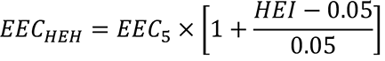
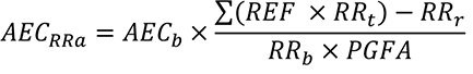
3. Section C406.2.5 - Renewable energy. When determining renewable energy credits in Equation 4-17 of Section C406.2.5, strike the phrase "...limited to 50 percent of the required credits in Section C406.1" in the definition of the factor AECRRa.
4. Table C406.2 - Efficiency measure credits. Use Table C406.2(2) credit values in place of Table C406.2(1) credit values.
C401.3.2 Fossil fuel equipment. Fossil fuel combustion appliances are permitted for HVAC heating, and shall comply with the applicable efficiency standards referenced in Section C403.3.3.2. Fossil fuel combustion appliances are permitted for service water heating, and shall comply with applicable efficiency standards referenced in Table C404.2.
C401.3.3 Additional efficiency credits. The number of additional efficiency credits required by Table C406.1 shall be increased by the number required in Table C401.3.3, modified as permitted in this section, and is in addition to the energy efficiency credits and load management credits required by Section C406.
EXCEPTION: | The required number of space heating additional efficiency credits are permitted to be reduced in the following instances: |
| 1. Low energy spaces in accordance with Section C402.1.1.1 and equipment buildings in accordance with Section C402.1.2 that are served by space heating systems shall comply with sufficient measures from Table C406.2(1) or Table C406.2(2) to achieve a minimum of 50 percent of the efficiency credits required for new construction by Table C401.3.3, modified as permitted in this section. |
| 2. Building additions that have less than 1,000 square feet of conditioned floor area and that comply with sufficient measures from Table C406.2(1) or Table C406.2(2) to achieve a minimum of 50 percent of the additional efficiency credits required for additions by Table C401.3.3, modified as permitted in this section. |
| 3. Semi-heated spaces in accordance with Section C402.1.1.2 that comply with sufficient measures from Table C406.2(1) or Table C406.2(2) to achieve a minimum of 50 percent of the space heating additional efficiency credits required by Table C401.3.3, modified as permitted in this section. |
| 4. Unconditioned spaces, open parking garages and unheated enclosed parking garages are not required to achieve the additional efficiency credits for space heating required by Table C401.3.3. |
TABLE C401.3.3
ADDITIONAL CREDITS REQUIRED
Measure Title | Applicable Section | Occupancy Group |
Group R-1 | Group R-2 | Group B | Group E | Group M | All Other |
New building - Additional efficiency credits required for space heating systems using the fossil fuel pathway | C401.3.3.1 | 7 | 24 | 101 | 38 | 111 | 56 |
New building - Additional efficiency credits required for service water heating systems using the fossil fuel pathway | C401.3.3.2 | 198 | 212 | 27 | 17 | 79 | 107 |
Building additions - Additional efficiency credits required for space heating systems using the fossil fuel pathway | C401.3.3.1 | 4 | 12 | 51 | 19 | 56 | 28 |
Building additions - Additional efficiency credits required for service water heating systems using the fossil fuel pathway | C402.3.3.2 | 99 | 106 | 14 | 9 | 40 | 54 |
C401.3.3.1 HVAC credit modification. The number of HVAC heating energy efficiency credits required by Table C401.3.3 is permitted to be decreased according to the following equation:
CR = A – (A × B/C)
Where: |
| CR | = | Additional credits required, rounded to the nearest whole number. |
| A | = | Baseline HVAC heating credits from Table C401.3.3. |
| B | = | Installed HVAC heating capacity in kBTU/h of HVAC heating appliances that comply with any of the exceptions to Section C403.1.4. |
| C | = | Total installed heating capacity in kBTU/h of all HVAC heating appliances. |
C401.3.3.2 Service water heating credit modification. The number of service water heating energy efficiency credits required by Table C401.3.3 is permitted to be decreased according to the following equation:
CR = A – (A × B/C)
Where: |
| CR | = | Additional credits required, rounded to the nearest whole number. |
| A | = | Baseline credits from Table C401.3.3. |
| B | = | Installed service water heating capacity in kBTU/h of service water heating appliances that comply with any of the exceptions to Section C404.2.1. |
| C | = | Total installed service water heating capacity in kBTU/h of all service water heating appliances. |
C401.3.4 Renewable energy credit limit. No more than 80 percent of the efficiency credits required by Sections C401.3.2.1 and C401.3.3.1 are permitted to be renewable energy credits defined in Section C406.2.5.
C401.3.5 Discrete area-weighting of additional required credits. In addition to the area-weighted credit requirements in Section C406.1.2, where a building includes multiple occupancies, the additional required credits per Table C401.3.3 shall be determined separately for each occupancy group. Additional required credits shall be prorated on an area-weighted basis for each occupancy group in the same manner as required project credits per Section C406.1.
1. Where a single space heating or service water heating system serves multiple occupancies, the number of additional required credits shall be prorated on an area-weighted basis for each occupancy served.
2. Additional required credits for envelope systems shall be prorated on an area-weighted basis for all occupancies.
3. Occupancies are permitted to be subdivided into discrete areas, with required and achieved credits for each area prorated on an area-weighted basis as required for the occupancy group.
C401.3.6 Electrification readiness. Additionally, the following provisions shall be required for new construction:
1. Provide a spare electrical branch circuit conduit to that appliance sized to support an equivalent heat pump appliance.
2. Provide spare electrical service entrance conduits for the purpose of upgrading the main electrical service to support all heat pump appliances throughout the building.
3. The main electrical room has sufficient space to accommodate increasing the main electrical service's size to support all heat pump appliances throughout the building.
4. Additional accommodations for the utility equipment comprised of transformer(s) and other equipment necessary to support an electrical service upgrade. These accommodations shall include adequate space on the site. If the utility equipment is located in a transformer vault, that vault must include not only the space but the additional cooling for larger transformer(s).
C401.4 Thermal envelope certificate. A permanent thermal envelope certificate shall be completed by an approved party. Such certificate shall be posted on a wall in the space where the space conditioning equipment is located, a utility room or other approved location. If located on an electrical panel, the certificate shall not cover or obstruct the visibility of the circuit directory label, service disconnect label, or other required labels. A copy of the certificate shall also be included in the construction files for the project. The certificate shall include:
1. R-values of insulation installed in or on ceilings, roofs, walls, foundations and slabs, crawlspace walls and floors, and ducts outside conditioned spaces.
2. U-factors and solar heat gain coefficients (SHGC) of fenestration.
3. Results from any building envelope air leakage testing performed on the building.
Where there is more than one value for any component of the building envelope, the certificate shall indicate the area-weighted average value where available. If the area-weighted average is not available, the certificate shall list each value that applies to 10 percent or more of the total component area.
Reviser's note: The bracketed material preceding the section above was supplied by the code reviser's office.
AMENDATORY SECTION(Amending WSR 22-14-091, 23-12-101, and 23-20-021 [22-14-091 and 23-12-101], filed 7/1/22, 6/7/23, and 9/25/23 [7/1/22 and 6/7/23], effective 3/15/24 [10/29/23])
WAC 51-11C-40314Section C403.1.4—HVAC heating equipment.
C403.1.4 Use of electric resistance and fossil fuel-fired HVAC heating equipment. HVAC heating energy shall not be provided by electric resistance or fossil fuel combustion appliances. For the purposes of this section, electric resistance HVAC heating appliances include, but are not limited to, electric baseboard, electric resistance fan coil and VAV electric resistance terminal reheat units and electric resistance boilers. For the purposes of this section, fossil fuel combustion HVAC heating appliances include, but are not limited to, appliances burning natural gas, heating oil, propane, or other fossil fuels.
EXCEPTIONS: | 1. Low heating capacity. Buildings or areas of buildings, other than dwelling units or sleeping units, that meet the interior temperature requirements of Chapter 12 of the International Building Code with a total installed HVAC heating capacity no greater than 8.5 Btu/h (2.5 watts) per square foot of conditioned space are permitted to be heated using electric resistance appliances. |
| 2. Dwelling and sleeping units. Dwelling or sleeping units are permitted to be heated using electric resistance appliances as long as the installed HVAC heating capacity in any separate space is not greater than: |
| 2.1. Seven hundred fifty (750) watts in Climate Zone 4, and 1000 watts in Climate Zone 5 in each habitable space with fenestration. |
| 2.2. One thousand (1,000) watts in Climate Zone 4, and 1300 watts in Climate Zone 5 for each habitable space that has two primary walls facing different cardinal directions, each with exterior fenestration. Bay windows and other minor offsets are not considered primary walls. |
| 2.3. Two hundred fifty (250) watts in spaces adjoining the building thermal envelope but without fenestration. |
| For the purposes of this section, habitable space is as defined in the International Building Code. For buildings in locations with exterior design conditions below 4°F (-16°C), an additional 250 watts above that allowed for Climate Zone 5 is permitted in each space with fenestration. |
| 3. Small buildings. Buildings with less than 2,500 square feet (232 m2) of conditioned floor area are permitted to be heated using electric resistance appliances. |
| 4. Defrost. Heat pumps are permitted to utilize electric resistance heating when a heat pump defrost cycle is required and is in operation. |
| 5. Air-to-air heat pumps. Buildings are permitted to utilize ((internal electric resistance heaters to supplement heat pump))supplemental heating sources for air-to-air heat pumps that meet all of the following conditions: |
| 5.1. Internal electric resistance heaters have controls that prevent supplemental heater operation when the heating load can be met by the heat pump alone during both steady-state operation and setback recovery. |
| 5.2. The heat pump controls are configured to use the compressor as the first stage of heating down to an outdoor air temperature of 17°F (-8°C) or lower except when in defrost. |
| EXCEPTIONS TO 5.2: |
| | 1. Packaged terminal heat pumps (PTHPs) that comply with the minimum heating efficiency requirements in Table C403.3.2(4) are exempt from heating pump controls capable of operating the compressor as the first stage of heating down to an outdoor air temperature of 17°F (-8°C) or lower. |
| | 2. Heat pumps whose minimum efficiency is regulated by NAECA and whose ratings meet the requirements shown in Table C403.3.2(2) and include all usage of internal electric resistance heating are exempt from heat pump controls capable of operating the compressor as the first state of heating down to an outdoor air temperature of 17°F (-8°C) or lower. |
| 5.3. The heat pump complies with one of the following: |
| 5.3.1. Controlled by a digital or electronic thermostat designed for heat pump use that energizes the supplemental heat only when the heat pump has insufficient capacity to maintain set point or to warm up the space at a sufficient rate. |
| 5.3.2. Controlled by a multistage space thermostat and an outdoor air thermostat wired to energize supplemental heat only on the last stage of the space thermostat and when outdoor air temperature is less than 32°F (0°C) except when in defrost. |
| 5.3.3. The minimum efficiency of the heat pump is regulated by NAECA, its rating meets the requirements shown in Table C403.3.2(2), and its rating includes all usage of internal electric resistance heating. |
| 5.4. The heat pump rated heating capacity is sized to meet the heating load at an outdoor air temperature of 32°F (0°C) or lower and has a rated heating capacity at 47°F (8°C) no less than 2 times greater than supplemental ((internal electric resistance)) heating capacity in Climate Zone 4 and no less than the supplemental ((internal electric resistance)) heating capacity in Climate Zone 5, or utilizes the smallest available factory-available internal electric resistance heater. |
| 6. Air-to-water heat pumps. Buildings are permitted to utilize electric resistance (for Climate Zone 4 or 5) or fossil fuel-fired (for Climate Zone 5) auxiliary heating to supplement heat pump heating for hydronic heating systems that meet all of the following conditions: |
| 6.1. Controls for the auxiliary ((electric resistance or fossil fuel-fired)) heating sources are configured to lock out the supplemental heat when the outside air temperature is above 36°F (2°C), unless the hot water supply temperature setpoint to the building heat coils cannot be maintained for 20 minutes. |
| 6.2. The heat pump controls are configured to use the compressor as the first stage of heating down to the lowest exterior design temperature for which the equipment is rated except during startup or defrost operation. |
| 6.3. The heat pump rated heating capacity at 47°F (8°C) is no less than 75 percent of the design heating load at 29°F (-2°C). |
| 7. Ground source heat pumps. Buildings are permitted to utilize ((electric resistance auxiliary heating to supplement))supplemental heating sources for heat pump heating for hydronic heating systems with ground source heat pump equipment that meets all of the following conditions: |
| 7.1. Controls for the auxiliary ((resistance)) heating sources are configured to lock out the supplemental heat when the equipment source-side entering water temperature is above 42°F (6°C), unless the hot water supply temperature setpoint to the building heat coils cannot be maintained for 20 minutes. |
| 7.2. The heat pump controls are configured to use the compressor as the first stage of heating. |
| 7.3. The ground source heat exchanger shall be sized so that the heat pump annual heating output is no less than 70 percent of the total annual heating output in the final year of a 30-year simulation using IGSHPA listed simulation software. |
| 8. Small systems. Buildings in which electric resistance or fossil fuel appliances, including decorative appliances, either provide less than 5 percent of the total building HVAC system heating capacity or serve less than 5 percent of the conditioned floor area. |
| 9. Specific conditions. Portions of buildings that require fossil fuel or electric resistance space heating for specific conditions approved by the code official for research, health care, process or other specific needs that cannot practicably be served by heat pump or other space heating systems. This does not constitute a blanket exception for any occupancy type. |
| 10. Kitchen make-up air. Make-up air for commercial kitchen exhaust systems required to be tempered by Section 508.1.1 of the International Mechanical Code is permitted to be heated by using fossil fuel in Climate Zone 5 or electric resistance in Climate Zone 4 or 5. |
| 11. District energy. Steam or hot water district energy systems that utilize fossil fuels as their primary source of heat energy, that serve multiple buildings, and that were already in existence prior to the effective date of this code, including more energy-efficient upgrades to such existing systems, are permitted to serve as the primary heating energy source. |
| 12. Heat tape. Heat tape is permitted where it protects water-filled equipment and piping located outside of the building thermal envelope, provided that it is configured and controlled to be automatically turned off when the outside air temperature is above 40°F (4°C). |
| 13. Temporary systems. Temporary electric resistance heating systems are permitted where serving future tenant spaces that are unfinished and unoccupied, provided that the heating equipment is sized and controlled to achieve interior space temperatures no higher than 40°F (4°C). |
| 14. Pasteurization. Electric resistance heat controls are permitted to reset the supply water temperature of hydronic heating systems that serve service water heating heat exchangers during pasteurization cycles of the service hot water storage volume. The hydronic heating system supply water temperature shall be configured to be 145°F (63°C) or lower during the pasteurization cycle. |
| 15. Freeze protection. Heating systems sized for spaces with indoor design conditions of 45°F (7°C) and intended for freeze protection are permitted to use electric resistance. The building envelope of any such space shall be insulated in compliance with Section C402.1. |
| 16. DOAS ERV auxiliary heat. Dedicated outdoor air systems with energy recovery ventilation are permitted to utilize fossil fuel for Climate Zone 5 or electric resistance in Climate Zone 4 or 5 for auxiliary heating to preheat outdoor air for defrost or as auxiliary supplemental heat to temper supply air to 55°F (13°C) or lower for buildings or portions of buildings that do not have hydronic heating systems. |
| 17. Low-carbon district energy systems. Low-carbon district energy systems that meet the definitions of low-carbon district energy exchange system or low-carbon district heating and cooling or heating only systems. |
| 18. Essential facilities. Groups I-2 and I-3 occupancies that by regulation are required to have in place redundant emergency backup systems. |
Reviser's note: The bracketed material preceding the section above was supplied by the code reviser's office.
AMENDATORY SECTION(Amending WSR 22-14-091, 23-12-101, and 23-20-021 [19-24-040], filed 7/1/22, 6/7/23, and 9/25/23 [11/26/19], effective 3/15/24 [7/1/20])
WAC 51-11C-40341Section C403.4.1—Thermostatic controls.
C403.4.1 Thermostatic controls. The supply of heating and cooling energy to each zone shall be controlled by individual thermostatic controls capable of responding to temperature within the zone. Controls in the same zone or in neighboring zones connected by openings larger than 10 percent of the floor area of either zone shall not allow for simultaneous heating and cooling. At a minimum, each floor of a building shall be considered as a separate zone. Controls on systems required to have economizers and serving single zones shall have multiple cooling stage capability and activate the economizer when appropriate as the first stage of cooling. See Section C403.5 for further economizer requirements. Where humidification or dehumidification or both is provided, at least one humidity control device shall be provided for each humidity control system.
EXCEPTIONS: | 1. Independent perimeter systems that are designed to offset only building envelope heat losses or gains or both serving one or more perimeter zones also served by an interior system provided: |
| 1.1. The perimeter system includes at least one thermostatic control zone for each building exposure having exterior walls facing only one orientation (within +/-45 degrees) (0.8 rad) for more than 50 contiguous feet (15,240 mm); |
| 1.2. The perimeter system heating and cooling supply is controlled by a thermostat located within the zones served by the system; and |
| 1.3. Controls are configured to prevent the perimeter system from operating in a different heating or cooling mode from the other equipment within the zones or from neighboring zones connected by openings larger than 10 percent of the floor area of either zone. |
| 2. Where an interior zone and a perimeter zone are open to each other with permanent openings larger than 10 percent of the floor area of either zone, cooling in the interior zone is permitted to operate at times when the perimeter zone is in heating and the interior zone temperature is at least 5°F (2.8°C) higher than the perimeter zone temperature. For the purposes of this exception, a permanent opening is an opening without doors or other operable closures. |
| 3. Dedicated outdoor air units that provide ventilation air, make-up air or replacement air for exhaust systems are permitted to be controlled based on supply air temperature. The supply air temperature shall be controlled to a maximum of 65°F (18.3°C) in heating and a minimum of 72°F (22°C) in cooling unless the supply air temperature is being reset based on the status of cooling or heating in the zones served or it being reset based on outdoor air temperature. |
C403.4.1.1 Heat pump supplementary heat control.((Unitary air cooled heat pumps shall include microprocessor controls that minimize supplemental heat usage during start-up, set-up, and defrost conditions. These controls shall anticipate need for heat and use compression heating as the first stage of heat. Controls shall indicate when supplemental heating is being used through visual means (e.g., LED indicators). Heat pumps equipped with supplementary heaters shall be installed with controls that prevent supplemental heater operation above 40°F (4.4°C).))Heat pumps equipped with internal electric resistance heaters shall have controls that prevent supplemental heater operation when the heating load can be met by the heat pump alone during both steady-state operation and setback recovery. Supplemental heater operation is permitted during outdoor coil defrost cycles. Heat pumps equipped with supplemental heaters shall comply with all conditions of Section C403.1.4.
EXCEPTIONS: | 1. Packaged terminal heat pumps (PTHPs) of less than 2 tons (24,000 Btu/hr) cooling capacity and whose ratings meet the requirements shown in Table C403.3.2(4) that have reverse-cycle demand defrost and are configured to operate in heat pump mode whenever the outdoor air temperatures are above 25°F (-3.9°C) and the unit is not in defrost. |
| 2. Heat pumps whose minimum efficiency is regulated by NAECA and whose ratings meet the requirements shown in Table C403.3.2(2) and include all usage of internal electric resistance heating. |
C403.4.1.2 Deadband. Where used to control both heating and cooling, zone thermostatic controls shall be configured to provide a temperature range or deadband of at least 5°F (2.8°C) within which the supply of heating and cooling energy to the zone is shut off or reduced to a minimum.
EXCEPTIONS: | 1. Thermostats requiring manual changeover between heating and cooling modes. |
| 2. Occupancies or applications requiring precision in indoor temperature control as approved by the code official. |
C403.4.1.3 Setpoint overlap restriction. Where a zone has a separate heating and a separate cooling thermostatic control located within the zone, a limit switch, mechanical stop or direct digital control system with software programming shall be configured to prevent the heating setpoint from exceeding the cooling setpoint and to maintain a deadband in accordance with Section C403.4.1.2.
C403.4.1.4 Heated or cooled vestibules and air curtains. The heating system for heated vestibules and air curtains with integral heating shall be provided with controls configured to shut off the source of heating when the outdoor air temperature is greater than 45°F (7°C). Vestibule heating and cooling systems shall be controlled by a thermostat located in the vestibule configured to limit heating to a temperature not greater than 60°F (16°C) and cooling to a temperature not less than 85°F (29°C).
EXCEPTIONS: | 1. Control of heating or cooling provided by transfer air that would otherwise be exhausted. |
| 2. Vestibule heating only systems are permitted to be controlled without an outdoor air temperature lockout when controlled by a thermostat located in the vestibule configured to limit heating to a temperature not greater than 45°F (7°C) where required for freeze protection of piping and sprinkler heads located in the vestibule. |
C403.4.1.5 Hot water boiler outdoor temperature setback control. Hot water boilers that supply heat to the building through one- or two-pipe heating systems shall have an outdoor setback control that lowers the boiler water temperature based on the outdoor temperature.
C403.4.1.6 Operable opening switches for HVAC system thermostatic control. Operable openings meeting the minimum size criteria of Section C402.5.11 and that open to the outdoors from a conditioned space must have controls configured to do the following once doors have been open for 5 minutes:
1. Disable the mechanical heating to the zone or reset the space heating temperature setpoint to 55°F or less within 5 minutes of the door open enable signal.
2. Disable the mechanical cooling to the zone or reset the space cooling temperature setpoint to 85°F or more within 5 minutes of the door open enable signal.
EXCEPTION: | Hydronic radiant heating and cooling systems. |
C403.4.1.7 Demand responsive controls. Thermostatic controls for heating or cooling systems shall be provided with demand responsive controls capable of increasing the cooling setpoint and decreasing the heating setpoint by no less than 4°F (2.2°C). The thermostatic controls shall be capable of performing all other functions provided by the control when the demand responsive controls are not available. Systems with direct digital control of individual zones report to a central control panel shall be capable of remotely increasing the cooling setpoint and decreasing the heating setpoint for each zone by no less than 4°F (2.2°C).
EXCEPTION: | Health care and assisted living facilities. |
Reviser's note: The bracketed material preceding the section above was supplied by the code reviser's office.
AMENDATORY SECTION(Amending WSR 22-14-091, 23-12-101, and 23-20-021 [20-21-080], filed 7/1/22, 6/7/23, and 9/25/23 [10/19/20], effective 3/15/24 [2/1/21])
WAC 51-11C-40600Section C406—Efficiency and load management measures.
C406.1 Additional energy efficiency and load management measures credit requirements. The project as defined in the building permit shall meet the following requirements as applicable:
1. New buildings, changes in space conditioning category, change of occupancy group, and building additions in accordance with Chapter 5 shall comply with sufficient measures from Section C406.2 so as to achieve the minimum number of required efficiency credits shown in Table C406.1.
2. New buildings greater than 5000 gross square feet of floor area shall comply with sufficient measures from Section C406.3 so as to achieve the minimum number of required load management credits shown in Table C406.1.
3. Tenant spaces shall comply in accordance with Section C406.1.1.
4. Projects using discrete area credit weighting shall comply in accordance with Section C406.1.2.
EXCEPTIONS: | 1. Low energy spaces in accordance with Section C402.1.1.1, equipment buildings in accordance with Section C402.1.2, unconditioned spaces, open parking garages, and enclosed parking garages that comply with sufficient measures from Table C406.2(1) to achieve a minimum of 50 percent of the efficiency credits required for new construction. Such projects shall be exempt from the load management requirements in Table C406.1. |
| 2. Building additions that have less than 1,000 square feet of conditioned floor area that comply with sufficient measures from Table C406.2(1) to achieve a minimum of 50 percent of the efficiency credits required for additions. |
| 3. Warehouses are exempt from the load management credit requirements in Table C406.1. |
Table C406.1
Energy Measure Credit Requirements
Required Credits for Projects | Section | Occupancy Group |
Group R-1 | Group R-2 | Group B | Group E | Group M | All Other |
New building energy efficiency credit requirement | C406.2 | 54 | 41 | 42 | 48 | 74 | 49 |
Building additions energy efficiency credit requirement | C406.2 | 27 | 20 | 21 | 23 | 36 | 21 |
If proposal 21-GP-136 is not included in the final adoption, then replace the two rows above with the following two rows: |
| New building energy efficiency credit requirement | C406.2 | 68 | 80 | 48 | 55 | 84 | 49 |
| Building additions energy efficiency credit requirement | C406.2 | 33 | 40 | 24 | 27 | 41 | 24 |
New building load management credit requirement | C406.3 | 12 | 15 | 27 | 15 | 13 | 26 |
C406.1.1 Tenant spaces. An initial tenant improvement shall comply with sufficient measures from Table C406.2(1) to achieve a minimum of efficiency credits required in Table C406.1 and are not required to achieve any load management credits. In projects with multiple tenant spaces, each tenant space is permitted to apply for different measures provided the weighted average of all areas in the project comply with the overall efficiency credit requirement in Table C406.1. Whole building or addition energy credits shall be allocated to tenant spaces in accordance with Sections C406.1.1.1 and C406.1.1.2.
EXCEPTIONS: | 1. An initial tenant improvement where the core and shell building complied via Section C407 in 2018 or later edition of the Washington State Energy Code. |
| 2. Previously occupied tenant spaces in existing buildings that comply with this code in accordance with Section C501. |
C406.1.1.1 Applicable envelope, renewable and elevator energy credits. Where an entire building or building addition complies with Section C406.2.4, C406.2.9, C406.2.10, or C406.2.14, under an initial tenant improvement permit, tenant spaces within the building qualify for the number of credits assigned to the occupancy group of the tenant space in accordance with Table C406.2(1). Where prior energy credits were achieved under the 2018 Washington State Energy Code, they shall be multiplied by 6 for applicability to this code.
C406.1.1.2 Applicable HVAC and service water heating credits. Where HVAC and service water heating systems and services are installed and comply with Section C406.2.4, C406.2.9, C406.2.10, or C406.2.14 under an initial tenant improvement permit, those systems and services shall be considered a part of the tenant space. Tenant spaces qualify for the credits assigned to the occupancy group of the tenant space in accordance with Table C406.2(1) if the tenant space includes the distribution system and equipment that the central HVAC systems or service water heating systems were designed to support.
C406.1.2 Discrete area-weighted project compliance. Discrete building areas ((shall be))are permitted to select different packages of measures provided that the whole project complies with both the energy and load management credit requirements. Compliance shall be determined as follows:
1. ((Project credit requirement shall be the individual occupancy group requirements from Table C406.1 for each discrete area weighted by discrete area conditioned floor area.))Required project credits shall be prorated on an area-weighted basis for each occupancy group by multiplying the occupancy group floor area by the number of credits required, and then dividing this value by the total area of all the occupancy groups combined. Where one occupancy group is less than 10 percent of the floor area of the project, use the primary occupancy group for all credits.
2. ((Determine the energy and load management credits achieved for each discrete area based on its occupancy group.))Occupancies are permitted to be subdivided into discrete areas, with required and achieved credits for each area prorated on an area-weighted basis as required for the occupancy group.
3. Where envelope or lighting power credits in Section C406.2.3.1, C406.2.3.2, or C406.2.3.12 are ((used))applied, the lighting power or envelope UA percentage reduction shall be calculated for the project as a whole to determine achieved credits.
((3.))4. Determine total project credits achieved by area-weighting ((individual discrete area credits by discrete area conditioned floor area))the achieved credits by occupancy group in the same manner as for required project credits.
((4.))5. A project complies when ((both))the achieved number of area-weighted energy and load management credits are equal to or greater than the required area-weighted ((project requirement))number of credits.
Reviser's note: The bracketed material preceding the section above was supplied by the code reviser's office.
AMENDATORY SECTION [NEW SECTION](Amending WSR 22-14-091, 23-12-101, and 23-20-021, filed 7/1/22, 6/7/23, and 9/25/23, effective 3/15/24)
WAC 51-11C-40620Section C406.2—Additional energy efficiency credit measures.
C406.2 Additional energy efficiency credit measures. Each energy efficiency credit measure used to meet credit requirements for the project shall include efficiency that is greater than the energy efficiency required for the building type and configuration requirements in Sections C402 through C405. Measures installed in the project that meet the requirements in Sections C406.2.1 through C406.2.14 shall achieve the credits listed for the measure and occupancy group in Table C406.2(1) or where calculations required by Sections C406.2.1 through C406.2.14 create or modify the table credits, the credits achieved shall be based upon the section calculations.
Table C406.2(1)
Efficiency Measure Credits
Measure Title | Applicable Section | Occupancy Group |
Group R-1 | Group R-2 | Group B | Group E | Group M | All Other |
1. Dwelling unit HVAC control | C406.2.1 | NA | 7 | NA | NA | NA | NA |
2. Improved HVAC TSPRa | C406.2.2.1 | NA | 8 | 11 | 17 | 22 | NA |
3. Improve cooling and fan efficiency | C406.2.2.2 | 2 | 2 | 3 | 4 | 3 | 2 |
4. Improve heating efficiency | C406.2.2.3 | 2 | 3 | 3 | 10 | 16 | 7 |
5. Improved low-carbon district energy system (10% better) | C406.2.2.4 | 3 | 3 | 4 | 11 | 17 | 8 |
6. Improved low-carbon district energy system (20% better)b | C406.2.2.5 | 9 | 10 | 12 | 33 | 52 | 24 |
7. High performance DOAS | C406.2.2.6 | 31 | 31 | 21 | 39 | 40 | 21/ (A) 40c |
8. Fault detection & diagnostics (FDD) | C406.2.2.7 | 2 | 2 | 2 | 6 | 9 | 4 |
9. 10% reduced lighting power | C406.2.3.1 | 7 | 4 | 18 | 16 | 20 | 15 |
10. 20% reduced lighting powerd | C406.2.3.2 | 13 | 8 | 36 | 32 | 40 | 29 |
11. Lamp efficacy improvement | C406.2.3.3 | 5 | 6 | NA | NA | NA | NA |
12. Residential lighting control | C406.2.4.1 | NA | 8 | NA | NA | NA | NA |
13. Enhanced lighting control | C406.2.4.2 | 1 | 1 | 6 | 6 | 11 | 6 |
14. Renewable energy | C406.2.5 | 7 | 12 | 13 | 13 | 10 | 11 |
15. Shower drain heat recovery | C406.2.6.1 | 9 | 30 | NA | 3 | NA | NA |
16. Service water heat recovery | C406.2.6.2 | 35 | 111 | 13 | 14 | (Grocery) 41e | NA |
17. Heat pump water heating | C406.2.6.3 | 81 | 261 | 17 | 33 | (Grocery) 95e | (A-2) 95f |
18. Heat trace system | C406.2.7.1 | 6 | 13 | 4 | 1 | NA | 6 |
19. Point of use water heater | C406.2.7.2 | NA | NA | 19 | 5 | NA | NA |
20. Service hot water distribution right sizing | C406.2.8 | 13 | 42 | NA | NA | NA | NA |
21. High performance service hot water temperature maintenance system | C406.2.9 | 6 | 13 | 4 | 1 | NA | 6 |
22. High efficiency service hot water circulation system | C406.2.10 | 3 | 6 | 2 | 1 | NA | 4 |
23. Low flow residential showerheads | C406.2.11 | 3 | 3 | NA | NA | NA | NA |
24. Enhanced envelope performanceg | C406.2.12 | 24 | 20 | 13 | 5 | 19 | 14 |
25. Base reduced air leakageg | C406.2.13.2 | 29 | 24 | 6 | 3 | 9 | 11 |
26. Enhanced reduced air leakageg | C406.2.13.3 | 53 | 44 | 11 | 5 | 16 | 20 |
27. Enhanced commercial kitchen equipment | C406.2.14 | 30h | 18h | 18h | 30h | 30h | 31h |
28. Enhanced residential kitchen equipment | C406.2.15 | 12 | 19 | NA | NA | NA | NA |
29. Enhanced residential laundry equipment | C406.2.16 | NA | 6 | NA | NA | NA | NA |
30. Heat pump clothes dryers | C406.2.17 | 6 | 6 | NA | NA | NA | NA |
31. Efficient elevator equipment | C406.2.18 | 3 | 5 | 5 | 5 | 4 | 4 |
a | Projects using Item 2 shall not use Items 3 through 5. |
b | Projects using C406.2.2.5 shall not use C406.2.2.4. |
c | For C406.2.2.6, occupancy Group A achieves 40 credits while other occupancy groups within the "all other" category achieve 21 credits. |
d | Projects using C406.2.3.2 shall not use C406.2.3.1. |
e | Service water heat recovery and heat pump water heating are available in Group M only for grocery stores larger than 10,000 ft2. Large mixed retail with full grocery and butcher sections shall achieve half the credits. This credit is not available where refrigeration recovery to heat service hot water is used to meet the requirements of Section C403.9.2.3. |
f | Heat pump water heating efficiency credits are available in the "all other" category only for Group A-2. |
g | Buildings or building areas that are exempt from the thermal envelope requirements in accordance with Sections C402.1.1 and C402.1.2, do not qualify for this package. |
h | Additional energy efficiency credits, up to the maximum shown in Table C406.2(1), shall be calculated according to Section C406.2.11. |
Table C406.2(2)
Efficiency Measure Credits for use with
Fossil Fuel Compliance Path
Measure Title | Applicable Section | Occupancy Group |
Group R-1 | Group R-2 | Group B | Group E | Group M | All Other |
1. Dwelling unit HVAC control | C406.2.1 | NA | 8 | NA | NA | NA | NA |
2. Improved HVAC TSPRa | C406.2.2.1 | NA | 9 | 12 | 19 | 24 | NA |
3. Improve cooling and fan efficiency | C406.2.2.2 | 12 | 8 | 14 | 8 | 10 | 10 |
4. Improve heating efficiency | C406.2.2.3 | 2 | 3 | 3 | 11 | 18 | 8 |
5. Improved low-carbon district energy system (10% better) | C406.2.2.4 | 3 | 3 | 4 | 12 | 19 | 9 |
6. Improved low-carbon district energy system (20% better)b | C406.2.2.5 | 10 | 11 | 13 | 36 | 57 | 26 |
7. High performance DOAS | C406.2.2.6 | 34 | 34 | 23 | 43 | 44 | 23/ (A) 40c |
8. Fault detection & diagnostics (FDD) | C406.2.2.7 | 2 | 2 | 2 | 6 | 9 | 4 |
9. 10% reduced lighting power | C406.2.3.1 | 7 | 4 | 18 | 16 | 20 | 15 |
10. 20% reduced lighting powerd | C406.2.3.2 | 13 | 8 | 36 | 32 | 40 | 29 |
11. Lamp efficacy improvement | C406.2.3.3 | 5 | 6 | NA | NA | NA | NA |
12. Residential lighting control | C406.2.4.1 | NA | 8 | NA | NA | NA | NA |
13. Enhanced lighting control | C406.2.4.2 | 1 | 1 | 6 | 6 | 11 | 6 |
14. Renewable energy | C406.2.5 | 7 | 12 | 13 | 13 | 10 | 11 |
15. Shower drain heat recovery | C406.2.6.1 | 10 | 33 | NA | 3 | NA | NA |
16. Service water heat recovery | C406.2.6.2 | 35 | 111 | 13 | 14 | (Grocery) 41e | NA |
17. Heat pump water heating | C406.2.6.3 | 135 | 163 | 17 | 33 | (Grocery) 95e | (A-2) 95f |
18. Heat trace system | C406.2.7.1 | 6 | 13 | 4 | 1 | NA | 6 |
19. Point of use water heater | C406.2.7.2 | NA | NA | 19 | 5 | NA | NA |
20. Service hot water distribution right sizing | C406.2.8 | 13 | 42 | NA | NA | NA | NA |
21. High performance service hot water temperature maintenance system | C406.2.9 | 6 | 13 | 4 | 1 | NA | 6 |
22. High efficiency service hot water circulation system | C406.2.10 | 3 | 6 | 2 | 1 | NA | 4 |
23. Low flow residential showerheads | C406.2.11 | 3 | 3 | NA | NA | NA | NA |
24. Enhanced envelope performanceg | C406.2.12 | 24 | 20 | 13 | 5 | 19 | 14 |
25. Base reduced air leakageg | C406.2.13.2 | 29 | 24 | 6 | 3 | 9 | 11 |
26. Enhanced reduced air leakageg | C406.2.13.3 | 53 | 44 | 11 | 5 | 16 | 20 |
27. Enhanced commercial kitchen equipment | C406.2.14 | 30h | 18h | 18h | 30h | 30h | 31h |
28. Enhanced residential kitchen equipment | C406.2.15 | 12 | 19 | NA | NA | NA | NA |
29. Enhanced residential laundry equipment | C406.2.16 | NA | 6 | NA | NA | NA | NA |
30. Heat pump clothes dryers | C406.2.17 | 6 | 6 | NA | NA | NA | NA |
31. Efficient elevator equipment | C406.2.18 | 3 | 5 | 5 | 5 | 4 | 4 |
a | Projects using Item 2 shall not use Items 3 through 5. |
b | Projects using C406.2.2.5 shall not use C406.2.2.4. |
c | For C406.2.2.6, occupancy Group A achieves 40 credits while other occupancy groups within the "all other" category achieve 21 credits. |
d | Projects using C406.2.3.2 shall not use C406.2.3.1. |
e | Service water heat recovery and heat pump water heating are available in Group M only for grocery stores larger than 10,000 ft2. Large mixed retail with full grocery and butcher sections shall achieve half the credits. This credit is not available where refrigeration recovery to heat service hot water is used to meet the requirements of Section C403.9.2.3. |
f | Heat pump water heating efficiency credits are available in the "all other" category only for Group A-2. |
g | Buildings or building areas that are exempt from the thermal envelope requirements in accordance with Sections C402.1.1 and C402.1.2, do not qualify for this package. |
h | Additional energy efficiency credits, up to the maximum shown in Table C406.2(2), shall be calculated according to Section C406.2.14. |
Reviser's note: The bracketed material preceding the section above was supplied by the code reviser's office.
AMENDATORY SECTION [NEW SECTION](Amending WSR 22-14-091, 23-12-101, and 23-20-021, filed 7/1/22, 6/7/23, and 9/25/23, effective 3/15/24)
WAC 51-11C-40622Section C406.2.2—HVAC measures.
C406.2.2 More efficient HVAC system performance. All heating and cooling systems shall meet the minimum requirements of Section C403 and efficiency improvements shall be referenced to the minimum efficiency requirements listed in the tables in Section C403.3.2. Where multiple efficiency requirements are listed, equipment shall meet the seasonal efficiencies including SEER, EER/IEER, IPLV or AFUE. Equipment that is larger than the maximum capacity range indicated in the tables in Section C403.3.2 shall utilize the values listed for the largest capacity equipment for the associated equipment type shown in the table. Where multiple individual heating or cooling systems serve the project, the improvement shall be the weighted average improvement based on individual system capacity.
For occupancies and systems required to comply with Section C403.1.1, credits are permitted to be achieved by meeting the requirements of Section C406.2.2.1. Other systems are permitted to achieve credits by meeting the requirements of either:
1. Section C406.2.2.2, More efficient HVAC equipment cooling and fan performance.
2. Section C406.2.2.3, More efficient HVAC equipment heating performance.
3. Section C406.2.2.4, High performance dedicated outdoor air system (DOAS).
4. Any combination of Sections C406.2.2.2, C406.2.2.3, and C406.2.2.4.
In addition, energy credits are permitted to be achieved for Section C406.2.2.7, Fault detection and diagnostics, where not otherwise required by Section C403.2.3 or C403.6.10(15).
C406.2.2.1 Improved HVAC TSPR. For systems required to comply with Section C403.1.1, the HVAC TSPR shall exceed the minimum requirement by five percent. If improvement is greater, the credits in Table C406.2(1) are permitted to be prorated up to a 20 percent improvement.
C406.2.2.2 More efficient HVAC equipment cooling and fan performance. No less than 90 percent of the total HVAC capacity serving the total conditioned floor area of the entire building, building addition or tenant space in accordance with Section C406.1.1 shall comply with Sections C406.2.2.2.1 through C406.2.2.2.3. Where individual equipment efficiencies vary, weigh them based on capacity.
C406.2.2.2.1 HVAC system selection. Equipment installed shall be types that are listed in the tables in Section C403.3.2.
C406.2.2.2.2 Cooling equipment efficiency. Equipment shall exceed the minimum cooling efficiency requirements listed in the tables in Section C403.3.2 by at least 5 percent. Where equipment exceeds the minimum annual cooling efficiency and heat rejection efficiency requirements by more than 5 percent, energy efficiency credits for cooling shall be determined using Equation 4-15, rounded to the nearest whole number.
(Equation 4-15)
Where: |
| EECHEC | = | Energy efficiency credits for cooling efficiency improvement. |
| EEC5 | = | Section C406.2.2.2 credits from Table C406.2(1). |
| CEI | = | The lesser of the improvement above minimum cooling efficiency requirements, minimum heat rejection efficiency requirements, or 20 percent (0.20). Where cooling efficiency varies by system, use the capacity weighted average efficiency improvement for all cooling equipment combined. The CEI expressed as a fraction shall be determined one of the following ways: |
| | | For metrics that increase as efficiency increases, CEI shall be calculated as follows: |
| CEI | = | CMDES | - 1 |
CMMIN |
| For metrics that decrease as efficiency increases, CEI shall be calculated as follows: |
| CEI | = | CMMIN | - 1 |
CMDES |
Where: |
| CMDES | = | Design cooling efficiency metric, part-load or annualized where available. |
| CMMIN | = | Minimum required cooling efficiency metric, part-load or annualized where available from Section C403.3.2. |
| For data centers using ASHRAE 90.4, CEI shall be calculated as follows: |
| CEI | = | AMLCMAX | - 1 |
AMLCDES |
Where: |
| AMLCDES | = | As-designed annualized mechanical load component calculated in accordance with ASHRAE 90.4 Section 6.5. |
| AMLCMAX | = | Maximum annualized mechanical load component from ASHRAE 90.4 Table 6.5. |
C406.2.2.2.3 Minimum fan efficiency. Where fan energy is not included in packaged equipment rating or it is and the fan size has been increased from the as-rated equipment condition, fan power or horsepower shall be less than 95 percent of the allowed fan power in Section C403.8.1.
C406.2.2.3 More efficient HVAC equipment heating performance. No less than 90 percent of the total HVAC capacity serving the total conditioned floor area of the entire building, building addition or tenant space in accordance with Section C406.1.1 shall comply with Sections C406.2.2.3.1 through C406.2.2.3.2.
C406.2.2.3.1 HVAC system selection. Equipment installed shall be types that are listed in the tables in Section C403.3.2. Electric resistance heating shall be limited to 20 percent of system capacity, with the exception of heat pump supplemental heating.
C406.2.2.3.2 Heating equipment efficiency. Equipment shall exceed the minimum heating efficiency requirements of the tables in Section C403.3.2 by at least 5 percent. Where equipment exceeds the minimum annual heating efficiency requirements by more than 5 percent, energy efficiency credits for heating shall be determined using Equation 4-16, rounded to the nearest whole number.
(Equation 4-16)
Where: |
| EECHEH | = | Energy efficiency credits for heating efficiency improvement. |
| EEC5 | = | Section C406.2.2.2 credits from Table C406.2(1). |
| HEI | = | The lesser of the improvement above minimum heating efficiency requirements or 20 percent (0.20). Where heating efficiency varies by system, use the capacity weighted average percentage for all heating equipment combined. For metrics that increase as efficiency increases, HEI shall be calculated as follows: |
Where: |
| HMDES | = | Design heating efficiency metric, part-load or annualized where available. |
| HMMIN | = | Minimum required heating efficiency metric, part-load or annualized where available from Section C403.3.2. |
EXCEPTION: | In low energy spaces complying with Section C402.1.1 and semi-heated spaces complying with Section C402.1.1.2, no less than 90 percent of the installed heating capacity is provided by electric infrared or gas-fired radiant heating equipment for localized heating applications. Such spaces shall achieve credits for EEC5. |
C406.2.2.4 Improved low-carbon district energy systems (10 percent better). Not less than 90 percent of the annual service hot water and space heating load, or not less than 90 percent of the annual service hot water, space heating, and space cooling load shall meet the criteria of Section C406.2.2.4.1 or C406.2.2.4.2.
Documentation for the low-carbon district system that is operational prior to the final inspection shall be provided to demonstrate that the definition as modified in Section C406.2.2.4.1 or C406.2.2.4.2 of low-carbon district energy exchange system is satisfied.
C406.2.2.4.1 Improved low-carbon district energy exchange systems (10 percent better). Low-carbon district energy exchange systems must demonstrate the following:
1. Forty-five percent of the annual district-system-net-load-met (sum of heating and cooling energy provided to attached buildings) comes from heat recovery between connected buildings, waste heat, or renewable energy resources; and
2. No more than 25 percent of the annual heat input to the system comes from fossil fuel or electric-resistance sources.
C406.2.2.4.2 Improved low-carbon district energy heating and cooling or heating only systems (10 percent better). Distribution losses must be accounted for and may not exceed 5 percent of the annual load delivered to buildings served by the system. Low-carbon district energy heating and cooling or heating only systems must demonstrate the following:
1. Forty-five percent of the annual district-system-net-load-met (sum of heating and cooling energy provided to attached buildings) comes from heat recovery between connected buildings, waste heat, or renewable energy resources and no more than 25 percent of the annual heat input to the system comes from fossil fuel or electric-resistance sources; or
2. No more than 10 percent of the system annual heat input to the system comes from fossil fuels or electric-resistance sources. The remaining annual heat input must be provided using heat pump technology with a minimum annual operating COP of 3.0.
C406.2.2.5 Improved low-carbon district energy systems (20 percent better). Not less than 90 percent of the annual service hot water and space heating load, or not less than 90 percent of the annual service hot water, space heating, and space cooling load shall meet the criteria of Section C406.2.2.5.1 or C406.2.2.5.2.
Documentation for the low-carbon district system that is operational prior to the final inspection shall be provided to demonstrate that the definition as modified in Section C406.2.2.4.1 or C406.2.2.4.2 of low-carbon district energy exchange system is satisfied.
C406.2.2.5.1 Improved low-carbon district energy exchange systems (20 percent better). Low-carbon district energy exchange systems must demonstrate the following:
1. Fifty percent of the annual district-system-net-load-met (sum of heating and cooling energy provided to attached buildings) comes from heat recovery between connected buildings, waste heat, or renewable energy resources; and
2. No more than 10 percent of the annual heat input to the system comes from fossil fuel or electric-resistance sources.
C406.2.2.5.2 Improved low-carbon district energy heating and cooling or heating only systems (20 percent better). Distribution losses must be accounted for and may not exceed 5 percent of the annual load delivered to buildings served by the system. Low-carbon district energy heating and cooling or heating only systems must demonstrate the following:
1. Fifty percent of the annual district-system-net-load-met (sum of heating and cooling energy provided to attached buildings) comes from heat recovery between connected buildings, waste heat, or renewable energy resources and no more than 10 percent of the annual heat input to the system comes from fossil fuel or electric-resistance sources; or
2. No more than 10 percent of the system annual heat input to the system comes from fossil fuels or electric-resistance sources. The remaining annual heat input must be provided using heat pump technology with a minimum annual operating COP of 4.0.
C406.2.2.6 High performance dedicated outdoor air system (DOAS). No less than 90 percent of the total conditioned floor area of the whole project, excluding floor area of unoccupied spaces that do not require ventilation as specified by the International Mechanical Code, shall be served by DOAS installed in accordance with Section C403.3.5 with the following adjustments:
1. Minimum heat recovery sensible effectiveness of 80 percent, calculated in accordance with Section C403.3.5.1.
2. Where design outdoor airflow is greater than 500 cfm (250 L/s), the DOAS shall be equipped with an economizer bypass, damper control, or wheel speed control that is active between 55°F (13°C) and 75°F (24°C) outdoor air temperature and minimizes energy recovery or maintains an appropriate DOAS leaving air temperature when the building is generally in cooling, based either on outdoor air temperature or a DDC zone-based cooling system reset.
3. DOAS total combined fan power shall be less than either:
3.1. 0.769 W/cfm (1.55 W/L/s) when calculated in accordance with Section C403.3.5.2.
3.2. Eighty percent of fan power allowance for a constant volume system when calculated in accordance with Section C406.8.1.
This option is not available to areas served by systems utilizing Section C403.2.2.1 exception 5.
C406.2.2.7 Fault detection and diagnostics system. A project not required to comply with Section C403.2.3 or C403.6.10(16) shall achieve energy credits for installing a fault detection and diagnostics system to monitor the HVAC system's performance and automatically identify faults. The installed system shall comply with items 1 through 6 in Section C403.2.3.
Reviser's note: The brackets and enclosed material in the text of the above section occurred in the copy filed by the agency and appear in the Register pursuant to the requirements of RCW 34.08.040. Reviser's note: The bracketed material preceding the section above was supplied by the code reviser's office.
AMENDATORY SECTION [NEW SECTION](Amending WSR 22-14-091, 23-12-101, and 23-20-021, filed 7/1/22, 6/7/23, and 9/25/23, effective 3/15/24)
WAC 51-11C-40623Section C406.2.3—Lighting measures.
C406.2.3 Reduced lighting power. Interior lighting within the whole project shall achieve credits by complying with Section C406.2.3.1 or C406.2.3.2. In Group R-1 and Group R-2 occupancies, dwelling and sleeping units shall comply with Section C406.2.3.3 and all other areas shall comply with section C406.2.3.1 or C406.2.3.2. Credits apply to the whole Group R-1 or Group R-2 area.
C406.2.3.1 Reduced lighting power option 1. The total connected interior lighting power calculated in accordance with Section C405.4.1 shall be 90 percent or less of the lighting power values specified in Table C405.4.2(1) times the floor area for the building types, or 90 percent or less of the total interior lighting power allowance calculated in accordance with Section C405.4.2.
C406.2.3.2 Reduced lighting power option 2. The total connected interior lighting power calculated in accordance with Section C405.4.1 shall be 80 percent or less of the lighting power values specified in Table C405.4.2(1) times the floor area of the building types, or 80 percent or less of the total interior lighting power allowance calculated in accordance with Section C405.4.2.
C406.2.3.3 Lamp efficacy. No less than 95 percent of the permanently installed light fixtures in dwelling units and sleeping units shall be provided by lamps with a minimum efficacy of 90 lumens per watt.
C406.2.4 Lighting controls. For buildings with nontransient dwelling units and sleeping units, energy credits shall be achieved by installation of systems that comply with the requirements of Section C406.2.4.1. All other buildings shall achieve energy credits by complying with Section C406.2.4.2. For buildings with mixed occupancies, credits shall be prorated based on floor area.
C406.2.4.1 Residential building lighting control. In buildings with nontransient dwelling units and sleeping units, lighting controls shall be configured to meet the following:
1. Each dwelling unit or sleeping unit shall have a main control by the main entrance that turns off all the lights and switched receptacles in the unit. The main control shall be permitted to have two controls, one for permanently wired lighting and one for switched receptacles. The main controls shall be clearly identified as "lights master off" and "switched outlets master off."
2. Switched receptacles shall be clearly identified and all switched receptacles shall be located within 12 inches of an unswitched receptacle. Each room shall have a minimum of two switched receptacles except bathrooms, kitchens, and closets.
C406.2.4.2 Enhanced digital lighting controls. Measure credits shall be achieved where no less than 50 percent of the gross floor area within the project has luminaires and lighting controls that include high end trim in compliance with Section C405.2.8.3 and either luminaire-level lighting controls in compliance with Section C405.2.8.1 or networked lighting controls in accordance with Section C405.2.8.2. Where general lighting in more than 50 percent of the gross floor area complies, the base credits from Table C406.2(1) shall be prorated as follows:
[Floor area with high end trim, %] x [Base energy credits for C406.2.4.2] / 50% |
Reviser's note: The brackets and enclosed material in the text of the above section occurred in the copy filed by the agency and appear in the Register pursuant to the requirements of RCW 34.08.040. Reviser's note: The bracketed material preceding the section above was supplied by the code reviser's office.
AMENDATORY SECTION [NEW SECTION](Amending WSR 22-14-091, 23-12-101, and 23-20-021, filed 7/1/22, 6/7/23, and 9/25/23, effective 3/15/24)
WAC 51-11C-40624Section C406.2.5—Renewable energy measures.
C406.2.5 On-site and off-site renewable energy. Projects installing on-site or off-site renewable energy systems with a capacity of at least 0.1 watts per gross square foot (1.08 W/m2) of building area in addition to the renewable energy capacity required elsewhere in this code shall achieve energy credits for this measure. Renewable energy systems achieving energy credits shall not be used to satisfy other requirements of this code. Off-site renewable energy systems shall comply with Sections C411.2.2 and C411.2.3. Credits shall be prorated from the table value in accordance with Equation 4-17.
(Equation 4-17)
Where: |
| AECRRa | = | Section C406.2.5 achieved energy credits for this project as calculated in accordance with Equation 4-17, limited to 50 percent of the required credits in Section C406.1. |
| RRt | = | Actual total rating of on-site and off-site renewable energy systems (W) for each type of renewable energy source in Table C411.2.1. |
| RRr | = | Rating of renewable energy systems required by Section C411.1, other sections in this code, or used to qualify for exceptions in this code (W). |
| RRb | = | 0.1 W/square foot (1.08 W/m2) |
| PGFA | = | Project gross floor area, square feet (m2). |
| AEC0.1 | = | Section C406.2.5 base credits from Table C406.2(1). |
| REF | = | Renewable Energy Factor from Table C411.2.1. |
Informative Note: | On-site renewable energy may include thermal service water heating or pool water heating, in which case ratings in Btu/h can be converted to W where W = Btu/h / 3.413. |
Reviser's note: The bracketed material preceding the section above was supplied by the code reviser's office.
AMENDATORY SECTION [NEW SECTION](Amending WSR 22-14-091, 23-12-101, and 23-20-021, filed 7/1/22, 6/7/23, and 9/25/23, effective 3/15/24)
WAC 51-11C-40625Section C406.2.6—Service water measures.
C406.2.6 Reduced energy use in service water heating. Buildings with service hot water heating equipment that serves the whole building, building addition or tenant space shall achieve credits through compliance with:
1. Section C406.2.6.1, C406.2.6.2, or C406.2.6.3.
2. Sections C406.2.6.1 and C406.2.6.2.
3. Sections C406.2.6.1 and C406.2.6.3.
C406.2.6.1 Shower drain heat recovery. Shower drain heat recovery units shall comply with Section C404.10 and preheat cold water supply to the showers. Potable waterside pressure loss shall be less than 10 psi (69 kPa) at maximum design flow. The efficiency of drain water heat recovery units shall be 54 percent in accordance with CSA B55.1. Full credits are applicable to the following building use types: Multi-family, hotel, motel, dormitory, and schools with locker room showers. Where not all showers in the project have drain heat recovery, the credit is adjusted based on the following:
[Section C406.2.6.1 table credits] x [Showers with drain recovery] / [Total number of showers] |
C406.2.6.2 Service water heating energy recovery. Not less than 30 percent of the annual service hot water heating energy use, or not less than 70 percent of the annual service hot water heating energy use in buildings with condenser water systems subject to the requirements of Section C403.9.2.1 or qualifying for one of its exceptions, shall be provided by one or more of the following:
1. Waste heat recovery from service hot water, heat recovery chillers, building equipment, process equipment, or other approved system. Qualifying heat recovery must be above and beyond heat recovery required by other sections of this code.
2. On-site renewable energy water-heating systems where not used to meet other requirements or to obtain other energy credits.
C406.2.6.3 Heat pump service water heating. Projects shall achieve credits through compliance with Section C406.2.6.3.1.
C406.2.6.3.1 Heat pump water heater. Credit shall be achieved where service hot water system capacity is 82,000 Btu/h (24kW) or less and is served using heat pump technology with no more than 4.5 kW of resistance supplemental heating and meets one of the following:
1. The COP rating shall be a minimum COP of 3.0 reported at the design leaving heat pump water temperature with an entering air temperature of 60°F (16°C) or lower. For water-source equipment, the COP rating will be reported at the design leaving load water temperature with an entering load water temperature of 74°F (23°C) or lower.
2. The uniform energy factor (UEF) shall be a minimum of 3.40 rated based on U.S. Department of Energy requirements.
C406.2.7 Improved service hot water temperature maintenance. For buildings with gross floor area greater than 10,000 square feet, credit shall be achieved when hot water temperature maintenance is installed in accordance with Section C406.2.7.1 or C406.2.7.2.
C406.2.7.1 Self-regulated heat trace system. The credit achieved shall be from Table C406.2(1). This system shall include self-regulating electric heat cables, connection kits and electronic controls. The cable shall be installed directly on the hot water supply pipes underneath the insulation to replace standby losses.
C406.2.7.2. Point of use water heater. The credit achieved shall be from Table C406.2(1) where any fixtures requiring hot water shall be supplied from a localized electric source of hot water with no recirculation or heat trace and limited to 2 kW and 6 gallons of storage. The supply pipe length from the point of use water heater to the termination of the fixture supply pipe shall be no more than 20 feet.
C406.2.8 Service hot water distribution right sizing. To achieve this credit, where Group R-1 and R-2 occupancies are served by a central service hot water system, the distribution system serving dwelling units, sleeping units and guestrooms shall be sized using Appendix M of the Uniform Plumbing Code.
C406.2.9 High performance service hot water temperature maintenance system. Systems with multiple riser service hot water circulation systems shall use only heat pump technology for temperature maintenance. The heat pump technology shall have a minimum COP of 3.0 or UEF of 3.4. For air-source equipment, the COP rating will be reported at the design leaving heat pump water temperature with an entering dry bulb air temperature of 60°F (16°C) or lower and a relative humidity of 50 percent or lower. For water-source equipment, the COP rating will be reported at the design leaving load side water temperature with an entering source side water temperature of 74°F (23°C) or lower. The system shall comply with the requirements of Section C404.7.1.
C406.2.10 High efficiency service hot water circulation system. Multiple riser service hot water circulation systems shall use a variable volume circulation pump controlled to vary the pump speed based on system demand and shall include self-actuated thermostatic balancing valves to control the system flow at each riser.
C406.2.11 Low flow showerheads for Group R-1 and R-2 occupancies. All showerheads installed in Group R-1 and R-2 dwelling units or sleeping units shall have a maximum listed flowrate of 1.25 gallons per minute or less at 80 psi operating pressure for fixed showerheads and a maximum listed flowrate of 1.50 gallons per minute or less at 80 psi operating pressure for handheld showerheads. When a shower is served by more than one showerhead, including handheld showerheads, the combined flow rate of all showerheads and/or other shower outlets controlled by a single valve shall not exceed 1.25 gallons per minute or less for fixed or 1.5 gallons per minute or less for handheld, or the shower shall be designed to allow only one shower outlet to be in operation at a time.
Reviser's note: The brackets and enclosed material in the text of the above section occurred in the copy filed by the agency and appear in the Register pursuant to the requirements of RCW 34.08.040. Reviser's note: The bracketed material preceding the section above was supplied by the code reviser's office.
AMENDATORY SECTION [NEW SECTION](Amending WSR 22-14-091, 23-12-101, and 23-20-021, filed 7/1/22, 6/7/23, and 9/25/23, effective 3/15/24)
WAC 51-11C-40627Section C406.2—Other measures.
C406.2.14 Enhanced commercial kitchen equipment. For buildings or areas designated as Group A-2, or facilities whose primary business type involves the use of a commercial kitchen with at least one gas or electric fryer, all fryers, dishwashers, steam cookers and ovens shall comply with all of the following:
1. Achieve the ENERGY STAR label in accordance with the specifications current as of January 1, 2022.
2. Be installed prior to the issuance of the certificate of occupancy.
3. Have the ENERGY STAR qualified model number listed on the construction documents submitted for permitting.
Energy efficiency credits for efficient commercial kitchen equipment shall be determined based on Equation 4-19, rounded to the nearest whole number.
(Equation 4-19)
Where: |
| AEECK | = | Section C406.2.14 table credits, to a maximum of those allowed in Table C406.2(1) for this option. |
| AreaK | = | Floor area of full-service kitchen (ft2 or m2). |
| AreaB | = | Gross floor area of building (ft2 or m2). |
C406.2.15 Residential kitchen equipment. For projects with Group R-1 and R-2 occupancies, energy credits shall be achieved where not less than 90 percent of dishwashers, refrigerators, and freezers comply with all of the following:
1. Achieve the ENERGY STAR Most Efficient label in accordance with the 2021 specifications.
2. Be installed prior to the issuance of the certificate of occupancy.
For Group R-1 where only some guestrooms are equipped with both refrigerators and dishwashers, the table credits shall be prorated as follows:
[Section C406.2.15 table credits] x [Floor area of guestrooms with kitchens] / [Total guestroom floor area] |
C406.2.16 Residential laundry appliances. For projects with Group R-2 occupancies, energy credits shall be achieved where not less than 90 percent of clothes washers and dryers in the project meet the following requirements:
1. Each dwelling unit contains in-unit washing washer and dryer equipment that meets the following requirements:
1.1. Achieve the ENERGY STAR Most Efficient label in accordance with the 2021 specifications.
1.2. Be installed prior to the issuance of the certificate of occupancy.
2. Where only some dwelling units are equipped with both washers and dryers, the table credits shall be prorated as follows:
[Section C406.2.16 table credits] x [Floor area of dwelling units with laundry] / [Total dwelling unit floor area] |
C406.2.17 Heat pump clothes dryers. Not less than 90 percent of domestic clothes dryers located in Group R-1 and R-2 of the whole project are ENERGY STAR rated heat pump dryers. Credit applies only to buildings where laundry facilities are provided either within each residential dwelling or sleeping units or grouped together in central multi-family use laundry rooms, or a mix of the two.
To claim this credit, the building permit drawings shall specify the appliance type and provide documentation of ENERGY STAR compliance. At the time of inspection, all appliances shall be installed and connected to utilities.
C406.2.18 Efficient elevator equipment. Qualifying elevators in the building shall be Energy Efficient Class A in accordance with ISO 25745-2, Table 7. Only buildings three or more floors above grade shall be permitted to use this credit. Credits shall be prorated based on Equation 4-18, rounded to the nearest whole credit. Projects with a compliance ratio (CRe in Equation 4-18) below 0.5 do not qualify for this credit.
(Equation 4-18)
Where: |
| ECe | = | Elevator energy credit achieved for building. |
| ECt | = | Section C406.2.18 table energy credit. |
| CRe | = | FA | |
| FB | |
| FA | = | Sum of floors served by Class A elevators. |
| FB | = | Sum of floors served by all building elevators and escalators. |
Reviser's note: The brackets and enclosed material in the text of the above section occurred in the copy filed by the agency and appear in the Register pursuant to the requirements of RCW 34.08.040. Reviser's note: The bracketed material preceding the section above was supplied by the code reviser's office.
AMENDATORY SECTION(Amending WSR 22-14-091, 23-12-101, and 23-20-021 [20-21-080], filed 7/1/22, 6/7/23, and 9/25/23 [10/19/20], effective 3/15/24 [2/1/21])
WAC 51-11C-40702Section C407.2—Mandatory requirements.
C407.2 Mandatory requirements. Compliance with Section C407 also requires compliance with those sections shown in Table C407.2.
The building permit application for projects utilizing this method shall include in one submittal all building and mechanical drawings and all information necessary to verify that the building envelope and mechanical design for the project corresponds with the annual energy analysis. If credit is proposed to be taken for lighting energy savings, then an electrical permit application shall also be submitted and approved prior to the issuance of the building permit. If credit is proposed to be taken for energy savings from other components, then the corresponding permit application (e.g., plumbing, boiler, etc.) shall also be submitted and approved prior to the building permit application. Otherwise, components of the project that would not be approved as part of a building permit application shall be modeled in the baseline in accordance with ANSI/ASHRAE/IESNA 90.1 Appendix G and in the proposed model in accordance with the requirements of the Washington State Energy Code.
Table C407.2
Mandatory Compliance Measures for Total Building Performance Method
Sectiona | Title | Comments |
Envelope |
C401 | Thermal envelope certificate | |
C402.2.7 | Airspaces | |
C402.5 | Air leakage | |
Mechanical |
C403.1.2 | Calculation of heating and cooling loads | |
C403.1.3 | Data centers | |
((C403.1.4 | Use of electric resistance and fossil fuel-fired HVAC heating equipment)) | |
C403.2 | System design | |
C403.3.1 | Equipment and system sizing | |
C403.3.2 | HVAC equipment performance requirements | |
C403.3.3 | Hot gas bypass limitation | |
C403.3.4.4 | Boiler turndown | |
((C403.3.6 | Ventilation for Group R occupancy)) | |
C403.4.1 | Thermostatic controls | |
C403.4.2 | Off-hour controls | |
C403.4.7 | Combustion heating equipment controls | |
C403.4.8 | Group R-1 hotel/motel guestrooms | See Section C403.7.4 |
C403.4.9 | Group R-2 and R-3 dwelling units | |
C403.4.10 | Group R-2 sleeping units | |
C403.4.11 | Direct digital control systems | |
C403.5.5 | Economizer fault detection and diagnostics (FDD) | |
C403.7 | Ventilation and exhaust systems | Except for C403.7.6.2 |
C403.8 | Fan and fan controls | |
C403.9.1.1 | Variable flow controls | For cooling tower fans ≥ 7.5 hp |
C403.9.1.2 | Limitation on centrifugal fan cooling towers | For open cooling towers |
C403.10 | Construction of HVAC elements | |
C403.11 | Mechanical systems located outside of the building thermal envelope | |
C403.14 | Commissioning | |
Service Water Heating |
C404 | Service water heating | Except for C404.2.1 |
Lighting and Electrical |
C405 | Electrical power and lighting systems | |
Other Requirements |
C407 | Total building performance | |
C408 | System commissioning | |
C409 | Energy metering | |
C410 | Refrigeration requirements | |
C411b | Renewable energy | |
C412 | Compressed air systems | |
a | Reference to a code section includes all the relative subsections except as indicated in the table. |
b | Compliance with any of these sections includes compliance with any exception to that section. |
Reviser's note: The bracketed material preceding the section above was supplied by the code reviser's office.
AMENDATORY SECTION(Amending WSR 22-14-091, 23-12-101, and 23-20-021 [19-24-040], filed 7/1/22, 6/7/23, and 9/25/23 [11/26/19], effective 3/15/24 [7/1/20])
WAC 51-11C-40703Section C407.3—Performance-based compliance.
C407.3 Performance-based compliance. Compliance with this section requires compliance with ASHRAE Standard 90.1 Appendix G, Performance Rating Method, in accordance with Standard 90.1 Section 4.2.1 with the following modifications:
1. The mandatory requirements of the Washington State Energy Code are required to be met, instead of those of Section G1.2.1a of ANSI/ASHRAE/IESNA 90.1.
2. Compliance with Section C407 requires meeting both ((an emissions and))a regulated site energy target and a total site energy reduction target in accordance with the following:
2.1. ((Carbon emissions))Regulated site energy target. The ((carbon emissions))regulated site energy target is focused on regulated load energy efficiency, thus shall be met only via regulated load savings without consideration of the contribution of on-site or off-site renewable energy or unregulated load savings. Adjustments to the PCI, to account for the contribution of renewable energy found in ANSI/ASHRAE/IESNA 90.1 Section 4.2.1.1 shall not be used. References to energy cost in Section 4.2.1.1 and Appendix G shall be replaced by ((carbon emissions calculated by multiplying site energy consumption by the carbon emission factor from Table C407.3(1)))site energy use. Heating or cooling energy provided by a district energy system may utilize coefficient of performance (COP) ratios acceptable to the code official for the respective district energy sources. The building performance factors in Table 4.2.1.1 of ANSI/ASHRAE/IESNA 90.1 shall be replaced with those in Table C407.3(2).
2.2. Total site energy target. The total site energy performance target shall be met including the contributions of on-site or off-site renewable energy as described in Section C411.2 as well as the contributions of improvements in unregulated loads as allowed by Section C407.3.4. The annual on-site and off-site renewable energy production (as adjusted by the factors in Table C411.2.1) shall be subtracted from the proposed building annual site energy use. Compliance with the site energy performance target requires that the proposed building site energy use/baseline building site energy use is less than or equal to the site energy performance target from Table C407.3(3).
3. Documentation requirements in Section G1.3.2.d shall be replaced by a list showing compliance with the mandatory provisions of Table C407.2.
4. Forms demonstrating compliance with Appendix G developed by the U.S. Department of Energy shall be completed and submitted to the code official. The forms are available at energycodes.gov/ashrae-standard-901-performance-based-compliance-form.
5. References to yet-to-be-designed future building components in the Proposed Building Performance column of Table G3.1 shall be modified to reference the corresponding sections of the Washington State Energy Code in lieu of the requirements of ANSI/ASHRAE/IESNA 90.1 in the following sections of the table:
5.1. No. 1, Design Model, subclause c.
5.2. No. 6, Lighting, subclause c.
5.3. No. 11, Service Water Heating System, subclause c.
5.4. No. 12, Receptacle and Other Loads, subclause b.
6. HVAC systems, subclauses c and d of Table G3.1, shall meet the following requirements:
6.1. For yet-to-be-designed systems in office, retail, library, education, and multifamily buildings and occupancies subject to the TSPR requirements of Section C403.1.1, the system type and efficiency parameters in the proposed model shall meet but not exceed those shown in Table D602.11 Standard Reference Design HVAC Systems.
6.2. For all other buildings and occupancies, the system type shall be the same as the system modeled in the baseline design and shall comply with but not exceed the requirements of Section C403 in lieu of ANSI/ASHRAE/IESNA 90.1.
6.3. For HVAC systems serving future tenant spaces, where the current building permit applies to only a portion of an HVAC system, and future components will receive HVAC services from systems included in the current building permit, those future components shall be modeled as the type required to complete the HVAC system portions under the current permit and shall meet but not exceed the requirements found in Section C403.
7. The requirements for proposed and baseline building lighting system shall be modified in accordance with Addendum af to ANSI/ASHRAE/IESNA 90.1.
8. Energy modeler qualifications. The energy analyst in responsible charge of the Section C407 submittal shall meet at least one of the following:
8.1. ASHRAE Building Energy Modeling Professional (BEMP) certification.
8.2. Association of Energy Engineer's Building Energy Simulation Analyst (BESA) certification.
8.3. Successful completion of at least five projects modeled following any version of ANSI/ASHRAE/IESNA 90.1 Appendix G within the last three years that were reviewed and approved by a code official or rating authority.
C407.3.1 Limits on nonmandatory measures. The Proposed Total UA of the proposed building shall be no more than 20 percent higher than the Allowed Total UA as defined in Section C402.1.5.
C407.3.2 On-site and off-site renewable energy accounting for use with Appendix G. Qualifying on-site and off-site renewable energy delivered or credited to the building project to comply with Section C407.3 item 2.2 shall meet the requirements of Section C411.2.
C407.3.3 Low-carbon district energy use with Appendix G. Qualifying low-carbon district heating and cooling or heating only systems and low-carbon district energy exchange systems shall meet the requirements of Section C407.3.3.1 or C407.3.3.2, as applicable.
C407.3.3.1 Utilization of low-carbon district heating and cooling or heating only systems. Applicable if heating and cooling or heating only is provided to the proposed building from a low-carbon district heating and cooling or heating only system that is fully operational prior to the final inspection. Proposed model shall account for all on-site HVAC and service hot water related equipment, such as circulation pump energy and heat-exchanger efficiency.
1. The following modifications shall be applied to Appendix G of ANSI/ASHRAE/IESNA 90.1 in addition to what is described in Section C407.3:
1.1. For low-carbon district heating and cooling systems, strike the text of Sections G3.1.1.1, G3.1.1.2, G3.1.1.3.1, G3.1.1.3.3, and G3.1.1.3.4. Baseline system shall be selected based on unmodified versions of Tables G3.1.1-3 and G3.1.1-4, ((with carbon emission factors from Table C407.3(1)))comparing energy use to determine compliance.
1.2. For low-carbon district heating only systems, strike the text of Sections G3.1.1.1, G3.1.1.3.1, and G3.1.1.3.4. Baseline system shall be selected based on unmodified versions of Tables G3.1.1-3 and G3.1.1-4, with carbon emission factors from Table C407.3(1).
2. Any heating or cooling energy provided by the low-carbon district heating and cooling or heating only system shall utilize ((footnote a of Table C407.3(1) for the district system carbon emission factor in the proposed model))a calculated energy use reduction factor acceptable to the code official to account for ((carbon emissions))energy use reduction from those end uses.
3. ((Carbon emission))Energy "credit" for any waste/recoverable heat exported to the low-carbon district heating and cooling or heating only systems shall be accounted for in the proposed design by multiplying the quantity of heat exported by the ((Carbon Emissions Factor established in footnote a of Table C407.3(1) multiplied by the)) appropriate seasonal utilization factor in Items 3.1 and 3.2 below. This ((carbon emissions))energy "credit" is subtracted from the total proposed design ((carbon emissions))energy use calculated in accordance with ASHRAE 90.1 Section 4.2.1.1.
3.1. Fifty percent of the waste heat exported to the low-carbon district heating and cooling or heating only systems during the months of October through December and January through March.
3.2. Twenty-five percent of the waste heat exported to the low-carbon district heating and cooling or heating only systems during the months of April through September.
EXCEPTION: | Waste heat exported from the building to the low-carbon district heating and cooling or heating only system shall not be subtracted from the proposed design ((carbon emissions))energy use if they are already accounted for in the calculation of ((emissions))energy use from the district heating or cooling plant as part of the district energy efficiency factor. |
Documentation for the low-carbon district system that is operational prior to the final inspection shall be provided to demonstrate the following:
1. Distribution losses must be accounted for and may not exceed 10 percent of the annual load delivered to buildings served by the system.
2. Twenty-five percent of the annual district-system-net-load-met (sum of heating and cooling energy provided to attached buildings) comes from heat recovery between connected buildings, waste heat or renewable energy resources and no more than 25 percent of the annual heat input to the system comes from fossil fuel or electric-resistance sources, or not more than 10 percent of the system annual heat input to the system comes from fossil fuel or electric-resistance sources.
C407.3.3.2 Utilization of low-carbon district energy exchange systems. Applicable if heating or cooling is provided to the proposed building from a low-carbon district energy exchange system that is fully operational prior to the final inspection. Proposed model shall account for all on-site HVAC and service hot water related equipment, such as circulation pump energy and heat-exchanger efficiency.
1. The following modifications shall be applied to Appendix G of ANSI/ASHRAE/IESNA 90.1 in addition to what is described in Section C407.3:
1.1. Strike the text of Sections G3.1.1.1, G3.1.1.2, G3.1.1.3, G3.1.1.3.1, G3.1.1.3.2, G3.1.1.3.3, and G3.1.1.3.4. Baseline system shall be selected based on unmodified versions of Tables G3.1.1-3 and G3.1.1-4((, with carbon emission factors from Table C407.3(1))).
2. Any heating or cooling energy provided by a low-carbon district energy exchange system shall utilize ((footnote a of Table C407.3(1) for the district system carbon emission factor))a calculated energy use reduction factor acceptable to the code official to account for the reduction in the proposed model.
3. ((Carbon emission))Energy use "credit" for any waste/recoverable heating exported to the low-carbon district energy exchange system shall be accounted for in the proposed design by multiplying the quantity of heat exported by the ((Carbon Emissions Factor established in footnote a of Table C407.3(1) multiplied by the)) appropriate seasonal utilization factor in Items 3.1 and 3.2 below. This ((carbon emissions))energy use "credit" is subtracted from the total proposed design ((carbon emissions))energy use calculated in accordance with ASHRAE 90.1 Section 4.2.1.1.
3.1. Fifty percent of the waste heat exported to the low-carbon district energy exchange system during the months of October through December and January through March.
3.2. Twenty-five percent of the waste heat exported to the low-carbon district energy exchange system during the months of April through September.
EXCEPTION: | Waste heat exported from the building to the low-carbon district heating and cooling or heating only system shall not be subtracted from the proposed design ((carbon emissions))energy use if they are already accounted for in the calculation of ((emissions))energy use from the district heating or cooling plant as a part of the district energy efficiency factor. |
Documentation for the low-carbon district system that is operational prior to the final inspection shall be provided to demonstrate that the definition of low-carbon district energy exchange system is satisfied.
C407.3.4 Credit for improvements in unregulated loads when using Appendix G. When calculating savings for site energy targets in accordance with Section C407.3 item 2.2, but not when calculating savings for emissions targets in accordance with Section C407.3 item 2.1, differences in the simulation of unregulated loads and equipment modeled in the baseline building design from those in the proposed design shall be approved by the code official based on documentation that the equipment installed in the proposed design represents a significant verifiable departure from documented current conventional practice. All unregulated equipment for which savings is claimed must be installed by the time of final inspection. The burden of this documentation is to demonstrate that accepted conventional practice would result in baseline building equipment different from that installed in the proposed design. Occupancy and occupancy schedules shall not be changed.
Reviser's note: The bracketed material preceding the section above was supplied by the code reviser's office.
AMENDATORY SECTION [NEW SECTION](Amending WSR 22-14-091, 23-12-101, and 23-20-021, filed 7/1/22, 6/7/23, and 9/25/23, effective 3/15/24)
WAC 51-11C-407031Tables for Section C407.3.
Table C407.3(1)
((Carbon Emissions Factors))Reserved
((Type | CO2e (lb/unit) | Unit |
Electricity | 0.44 | kWh |
Natural gas | 11.7 | Therm |
Oil | 19.2 | Gallon |
Propane | 10.5 | Gallon |
Othera | 195.00 | mmBtu |
On-site renewable energy | 0.00 | |
a | District energy systems may use alternative emissions factors supported by calculations approved by the code official.)) |
Table C407.3(2)
Building Performance Factors (BPF) to be used for Compliance with Section C407.3
Building Area Type | Building Performance Factor |
Multifamily | ((0.55))0.51 |
Health care/hospital | ((0.71))0.70 |
Hotel/motel | ((0.53))0.51 |
Office | ((0.45))0.44 |
Restaurant | ((0.35))0.33 |
Retail | 0.41 |
School | ((0.36))0.35 |
Warehouse | ((0.19))0.18 |
All others | ((0.44))0.43 |
Table C407.3(3)
Site Energy Performance Targets to be used for Compliance with Section C407.3
Building Area Type | Site Energy Performance Targets |
Multifamily | 0.59 |
Health care/hospital | 0.72 |
Hotel/motel | 0.62 |
Office | 0.58 |
Restaurant | 0.59 |
Retail | 0.46 |
School | 0.52 |
Warehouse | 0.29 |
All others | 0.55 |
Reviser's note: The bracketed material preceding the section above was supplied by the code reviser's office.
AMENDATORY SECTION(Amending WSR 22-14-091, 23-12-101, and 23-20-021 [19-24-040], filed 7/1/22, 6/7/23, and 9/25/23 [11/26/19], effective 3/15/24 [7/1/20])
WAC 51-11C-41100Section C411—Renewable energy.
C411.1 On-site renewable energy. Each new building, or addition larger than 10,000 square feet of gross conditioned floor area, shall include a renewable energy generation system consisting of not less than 0.5 W/ft2 or 1.7 Btu/ft2 multiplied by the sum of the gross conditioned floor area.
EXCEPTIONS: | 1. Any building where more than 50 percent of the roof area is shaded from direct beam sunlight by natural objects or by structures that are not part of the building for more than 2500 annual hours between 8:00 a.m. and 4:00 p.m. |
| 2. Any building where more than 80 percent of the roof area is covered by any combination of equipment other than for on-site renewable energy systems, planters, vegetated space, skylights or occupied roof deck. |
| 3. Buildings which can document they do not have adequate roof area to install the required on-site solar and that comply with Section C411.1.1 may install a lesser amount of on-site renewables but not zero. |
C411.1.1 Additional efficiency credits. Buildings which qualify for one of the exceptions in Section C411.1 to omit installation of on-site renewable energy must achieve an additional 18 efficiency package credits from Table C406.2(1). The additional 18 credits can be reduced based on a prorated fraction of renewable capacity that is installed on-site.
On-site renewable energy installations of lower than required capacity can be counted proportionally toward achievement of required or additional efficiency credits in Section C411.1.1 based on the capacity of renewable energy installed compared to the requirements of Section C411.1.
C411.2 On-site and off-site renewable energy accounting. Qualifying on-site and off-site renewable energy delivered or credited to the building project to comply with this code shall meet the requirements of this section. Renewable energy certificates for an on-site or off-site renewable energy system shall be retired on behalf of the building owner for a period of not less than 15 years and tracked in accordance with Section C411.2.3 and submitted to the code official as part of the permit application.
C411.2.1 Qualifying types of off-site renewable energy systems. The following are considered qualifying off-site renewable energy systems:
1. Self-generation (an off-site renewable energy system owned by the building project owner) systems complying with Section C411.2.2.
2. Community renewable energy facility systems complying with Section C411.2.2.
3. Purchase contracts complying with Section C411.2.3.
4. Each source of renewable energy delivered to or credited to the building project shall be connected to the Western Interconnection and energy or capacity multiplied by the factors in Table C411.2.1.
Table C411.2.1
Multipliers for Renewable Energy Procurement Methods
Location | Renewable Energy Source | Renewable Energy Factor |
In the state of Washington | Western Interconnected | In the states of Oregon or Idaho |
On-site | On-site renewable energy system | 1 | NA | NA |
Off-site | Directly owned off-site renewable energy system that begins operation after submission of the initial permit application | 0.95 | 0.75 | 0.85 |
Off-site | Community renewable energy facility that begins operation after submission of the initial permit application | 0.95 | 0.75 | 0.85 |
Off-site | Directly owned off-site renewable energy system that begins operation before submission of the initial permit application | 0.75 | 0.55 | 0.65 |
Off-site | Community renewable energy facility that begins operation before submission of the initial permit application | 0.75 | 0.55 | 0.65 |
Off-site | Renewable Power Purchase Agreement (PPA) | 0.75 | 0.55 | 0.65 |
C411.2.2 Documentation requirements for off-site renewable energy systems. Off-site renewable energy delivered or credited to the building project to comply with Section C407.3 item 2.2 shall be subject to a legally binding contract to procure qualifying off-site renewable energy. Qualifying off-site renewable energy shall meet the following requirements:
1. Documentation of off-site renewable energy procurement shall be submitted to the code official.
2. The purchase contract shall have a duration of not less than 15 years. The contract shall be structured to survive a partial or full transfer of ownership of the building property.
3. Records on renewable power purchased by the building owner from the off-site renewable energy generator that specifically assign the RECs to the building owner shall be retained or retired by the building owner on behalf of the entity demonstrating financial or operational control over the building seeking compliance to this standard and made available for inspection by the code official upon request.
4. Where multiple buildings in a building project are allocated energy procured by a contract subject to this section, the owner shall allocate for not less than 15 years the energy procured by the contract to the buildings in the building project. A plan on operation shall be developed which shall indicate how renewable energy produced from on-site or off-site systems that is not allocated before issuance of the certificate of occupancy will be allocated to new or existing buildings included in the building project.
C411.2.3 Renewable energy certificate (REC) tracking. For multitenant buildings where RECs are transferred to tenants, the plan for operation shall include procedures for tracking the quantity and vintage of RECs that are required to be retained and retired. The plan shall include provisions to transfer the RECs to building tenants, or to retire RECs on their behalf, in proportion to the gross conditioned and semi-heated floor area leased or rented. The plan shall include provisions to use a REC tracking system that meets the requirements of Section V.B of the Green-e Framework for Renewable Energy Certification. The plan shall describe how the building owner will procure alternative qualifying renewable energy in the case that the renewable energy producer ceases.
C411.3 Solar readiness. A solar zone shall be provided on buildings that are 20 stories or less in height above grade plan. The solar zone shall be located on the roof of the building or on another structure elsewhere on the site. The solar zone shall be in accordance with this section and the International Fire Code.
EXCEPTION: | A solar zone is not required under the following conditions: |
| 1. Where the solar exposure of the building's roof area is less than 75 percent of that of an unshaded area, as defined in Section C411.5, in the same location, as measured by one of the following: |
| 1.1. Incident solar radiation expressed in kWh/ft2-yr using typical meteorological year (TMY) data. |
| 1.2. Annual sunlight exposure expressed in cumulative hours per year using TMY data. |
| 1.3. Shadow studies indicating that the roof area is more than 25 percent in shadow, on September 21st at 10 a.m., 11 a.m., 12 p.m., 1 p.m., and 2 p.m. solar time. |
| 2. Buildings, building additions, changes in space conditioning or occupancy where the total floor area is equal to or less than 500 square feet. |
C411.3.1 Minimum area. The minimum area of the solar zone shall be determined by one of the following methods, whichever results in the smaller area:
1. Forty percent of roof area. The roof area shall be calculated as the horizontally projected gross roof area less the area covered by skylights, occupied roof decks, mechanical equipment, mechanical equipment service clearances, and planted areas.
2. Twenty percent of electrical service size. The electrical service size is the rated capacity of the total of all electrical services to the building, and the required solar zone size shall be based upon 10 peak watts of photovoltaic per square foot.
EXCEPTION: | Subject to the approval of the code official, buildings with extensive rooftop equipment that would make full compliance with this section impractical shall be permitted to reduce the size of the solar zone required by Section C411.3 to the maximum practicable area. |
C411.3.2 Contiguous area. The solar zone is permitted to be comprised of separated subzones. Each subzone shall be at least 5 feet wide in the narrowest dimension.
C411.3.3 Obstructions. The solar zone shall be free of pipes, vents, ducts, HVAC equipment, skylights and other obstructions, except those serving photovoltaic systems within the solar zone. The solar zone is permitted to be located above any such obstructions, provided that the racking for support of the future system is installed at the time of construction, the elevated solar zone does not shade other portions of the solar zone, and its height is permitted by the International Building Code. Photovoltaic or solar water heating systems are permitted to be installed within the solar zone.
C411.3.4 Shading. The solar zone shall be set back from any existing or new object on the building or site that is located south, east or west of the solar zone a distance at least two times the object's height above the nearest point on the roof surface. Such objects include, but are not limited to, taller portions of the building itself, parapets, chimneys, antennas, signage, rooftop equipment, trees, and roof plantings. No portion of the solar zone shall be located on a roof slope greater than 2:12 that faces within 45 degrees of true north.
C411.3.5 Access. Areas contiguous to the solar zone shall provide access pathways and provisions for emergency smoke ventilation as required by the International Fire Code.
C411.3.6 Structural integrity. The as-designed dead load and live load for the solar zone shall be clearly marked on the record drawings and shall accommodate future photovoltaic system arrays at an assumed dead load of 4 pounds per square foot in addition to other required live and dead loads. A location for future inverters shall be designated either within or adjacent to the solar zone, with a minimum area of 2 square feet for each 1000 square feet of solar zone area, and shall accommodate an assume dead load of 175 pounds per square foot. Where photovoltaic systems are installed in the solar zone, structural analysis shall be based upon calculated loads, not upon these assumed loads.
C411.3.7 Photovoltaic interconnection. Interconnection of the future photovoltaic system shall be provided for at the main service panel, either ahead of the service disconnecting means or at the end of the bus opposite the service disconnecting means, in one of the following forms:
1. A space for the mounting of a future overcurrent device, sized to accommodate the largest standard rated overcurrent device that is less than 20 percent of the bus rating.
2. Lugs sized to accommodate conductors with an ampacity of at least 20 percent of the bus rating, to enable the mounting of an external overcurrent device for interconnection.
The electrical construction documents shall indicate all of the following:
1. Solar zone boundaries and access pathways.
2. Location for future inverters and metering equipment.
3. Route for future wiring between the photovoltaic panels and the inverter, and between the inverter and the main service panel.
Reviser's note: The bracketed material preceding the section above was supplied by the code reviser's office.
AMENDATORY SECTION(Amending WSR 22-14-091, 23-12-101, and 23-20-021 [20-21-080], filed 7/1/22, 6/7/23, and 9/25/23 [10/19/20], effective 3/15/24 [2/1/21])
WAC 51-11C-50000Chapter 5 [CE]—Existing buildings.
C501 General.
C501.1 Scope. The provisions of this chapter shall control the alteration, repair, addition and change of occupancy of existing buildings and structures.
C501.1.1 Existing buildings. Except as specified in this chapter, this code shall not be used to require the removal, alteration or abandonment of, nor prevent the continued use and maintenance of, an existing building or building system lawfully in existence at the time of adoption of this code. Unaltered portions of existing buildings used for residential purposes shall not be required to comply with this code.
C501.2 Compliance.Additions, alterations, repairs, changes in space conditioning and changes of occupancy to, or relocation of, existing buildings and structures shall comply with Section C502, C503, C504, or C505 of this code, and with all applicable provisions in the International Building Code, International Existing Building Code, International Fire Code, International Fuel Gas Code, International Mechanical Code, Uniform Plumbing Code, and NFPA 70.
C501.2.1 U-factor requirements for additions and alterations. For existing building projects where an addition or building envelope alteration area is combined with existing-to-remain building areas to demonstrate compliance with this code as a whole building, the U-factors applied to existing-to-remain envelope assemblies shall be in accordance with record documents.
EXCEPTION: | If accurate record documents are not available, U-factors for the existing envelope assemblies may be in accordance with the edition of the Washington State Energy Code that was in effect at the time the building was permitted, or as approved by the code official. |
C501.2.2 Calculations of mechanical heating and cooling loads for alterations. For the installation of new or replacement mechanical equipment that serves existing building areas, design loads associated with heating, cooling and ventilation of the existing building areas served shall be determined in accordance with Section C403.1.2.
R-values and U-factors used to determine existing thermal envelope performance for the purpose of calculating design loads shall be in accordance with record documents or existing conditions.
EXCEPTION: | If accurate record documents are not available, R-values and U-factors used to determine existing building thermal envelope performance may be in accordance with the edition of the Washington State Energy Code that was in effect at the time the building was permitted, or as approved by the code official. |
C501.3 Maintenance. Buildings and structures, and parts thereof, shall be maintained in a safe and sanitary condition. Devices and systems which are required by this code shall be maintained in conformance with the code edition under which installed. The owner or the owner's authorized agent shall be responsible for the maintenance of buildings and structures. The requirements of this chapter shall not provide the basis for removal or abrogation of energy conservation, fire protection and safety systems and devices in existing structures.
C501.4 New and replacement materials. Except as otherwise required or permitted by this code, materials permitted by the applicable code for new construction shall be used. Like materials shall be permitted for repairs, provided no hazard to life, health or property is created. Hazardous materials shall not be used where the code for new construction would not permit their use in buildings of similar occupancy, purpose and location.
C501.5 Historic buildings. Provisions of this code relating to the construction, repair, alteration, restoration and movement of structures, and change of occupancy shall not be mandatory for historic buildings provided that a report has been submitted to the code official and signed by a registered design professional, or a representative of the state historic preservation office or the historic preservation authority having jurisdiction, demonstrating that compliance with that provision would threaten, degrade or destroy the historic form, fabric or function of the building.
C501.6 Commissioning. Existing building systems shall be commissioned in accordance with Section C408. For the purposes of meeting the commissioning thresholds in Section C408.1, only the new and altered system capacities are considered when determining whether the project is exempt from some portion of the commissioning process.
Reviser's note: The brackets and enclosed material following the text of the above section occurred in the copy filed by the agency and appear in the Register pursuant to the requirements of RCW 34.08.040. Reviser's note: The bracketed material preceding the section above was supplied by the code reviser's office.
AMENDATORY SECTION(Amending WSR 22-14-091, 23-12-101, and 23-20-021 [20-21-080], filed 7/1/22, 6/7/23, and 9/25/23 [10/19/20], effective 3/15/24 [2/1/21])
WAC 51-11C-50300Section C503—Alterations.
C503.1 General. Alterations to any building or structure shall comply with the requirements of Section C503 and the code for new construction. Alterations to an existing building, building system or portion thereof shall conform to the provisions of this code as they relate to new construction without requiring the unaltered portions of the existing building or building system to comply with this code. Alterations shall be such that the existing building or structure is no less conforming with the provisions of this code than the existing building or structure was prior to the alteration. The additional energy efficiency credit requirements in Section C406.1 and the renewable energy requirements in Section C411 do not apply to alterations.
EXCEPTION: | The following alterations need not comply with the requirements for new construction provided the energy use of the building is not increased: |
| 1. Storm windows installed over existing fenestration. |
| 2. Surface applied window film installed on existing single pane fenestration assemblies to reduce solar heat gain provided the code does not require the glazing fenestration to be replaced. |
| 3. Existing ceiling, wall or floor cavities exposed during construction provided that these cavities are insulated to full depth with insulation having a minimum nominal value of R-3.0 per inch installed per Section C402. |
| 4. Construction where the existing roof, wall or floor cavity is not exposed. |
| 5. Roof recover. |
| 6. Air barriers shall not be required for roof recover and roof replacement where the alterations or renovations to the building do not include alterations, renovations or repairs to the remainder of the building envelope. |
| 7. Replacement of existing doors that separate conditioned space from the exterior shall not require the installation of a vestibule or revolving door, provided however that an existing vestibule that separates a conditioned space from the exterior shall not be removed. |
C503.2 Reserved.
C503.3 Building envelope. New building envelope assemblies that are part of the alteration shall comply with Sections C402.1 through C402.5 and Sections C503.3.1 through C503.3.3.
EXCEPTION: | Air leakage testing is not required for alterations and repairs, unless the project includes a change in space conditioning according to Section C503.2 or a change of occupancy or use according to Section C505.1. |
C503.3.1 Roof replacement.Roof replacements shall comply with Table C402.1.3 or C402.1.4 where the existing roof assembly is part of the building thermal envelope and contains no insulation or the insulation is located entirely above the roof deck. In no case shall the R-value of the roof insulation be reduced or the U-factor of the roof assembly be increased as part of the roof replacement.
C503.3.2 Vertical fenestration. Alterations that include the addition of new vertical fenestration area shall comply with the following:
1. Where the addition of new vertical fenestration area results in a total building vertical fenestration area less than or equal to the maximum allowed by Section C402.4.1, the alteration shall comply with Section C402.4.
2. Where the addition of new vertical fenestration area result in a total building vertical fenestration area greater than the maximum allowed by Section C402.4.1 (regardless of the ratio prior to the addition), the alteration shall comply with one of the following:
2.1. Vertical fenestration alternate in accordance with Section C402.1.3 for the new vertical fenestration added.
2.2. Vertical fenestration alternate in accordance with Section C402.4.1.1 for the area adjacent to the new vertical fenestration added.
2.3. Existing building and alteration areas are combined to demonstrate compliance with the component performance alternate in accordance with Section C402.1.5 for the whole building. U-factors applied to existing envelope assemblies in the UA calculation shall comply with Section C501.2.1. The Proposed Total UA is allowed to be up to 110 percent of the Allowed Total UA.
2.4. Total building performance in accordance with Section C407 for the whole building. The total annual carbon emissions from energy consumption of the proposed design is allowed to be up to 110 percent of the annual carbon emissions from energy consumption allowed in accordance with Section C407.3.
EXCEPTION: | Where approved by the code official, additional fenestration is permitted where sufficient envelope upgrades beyond those required by other sections of this code are included in the project so that the addition of new vertical fenestration does not cause an increase in the overall energy use of the building. |
C503.3.2.1 Replacement fenestration products. Where some or all of an existing fenestration unit is replaced with a new fenestration product, including sash and glazing, the replacement fenestration unit shall meet the applicable requirements for U-factor and SHGC in Table C402.4.
EXCEPTION: | An area-weighted average of the U-factor of replacement fenestration products being installed in the building for each fenestration product category listed in Table C402.4 shall be permitted to satisfy the U-factor requirements for each fenestration product category listed in Table C402.4. Individual fenestration products from different product categories listed in Table C402.4 shall not be combined in calculating the area-weighted average U-factor. |
C503.3.3 Skylights. Alterations that include the addition of new skylight area shall comply with the following:
1. Where the addition of new skylight area results in a total building skylight area less than or equal to the maximum allowed by Section C402.4.1, the alteration shall comply with Section C402.4.
2. Where the addition of new skylight area results in a total building skylight area greater than the maximum allowed by Section C402.4.1 (regardless of the ratio prior to the addition), the alteration shall comply with one of the following:
2.1. Existing building and alteration area are combined to demonstrate compliance with the component performance alternative with target area adjustment in accordance with Section C402.1.5 for the whole building. U-factors applied to existing envelope assemblies in the UA calculation shall comply with Section C501.2.1. The Proposed Total UA is allowed to be up to 110 percent of the Allowed Total UA.
2.2. Total building performance in accordance with Section C407 for the whole building. The annual carbon emissions from energy consumption of the proposed design is allowed to be up to 110 percent of the annual carbon emissions from energy consumption allowed in accordance with Section C407.3.
EXCEPTION: | Additional envelope upgrades are included in the project so the addition of new skylights does not cause a reduction in overall building energy efficiency, as approved by the code official. |
C503.4 Building mechanical systems. Components of existing mechanical systems that are altered or replaced shall comply with Section C403 or Section C407, unless specifically exempted in this section, and Sections C408.2, C409.5, C501.2.2, C501.6, and C503.4.2 through C503.4.5. Additions or alterations shall not be made to an existing mechanical system that will cause the existing system to become out of compliance.
EXCEPTIONS: | 1. Existing mechanical systems are not required to be modified to comply with Section C403.3.5 where mechanical cooling capacity is not added to a system that did not have cooling capacity prior to the alteration. |
| 2. Compliance with Section C403.1.4 is not required where the alteration does not include replacement of a heating appliance. |
| 3. Alternate mechanical system designs that are not in full compliance with this code may be approved when the code official determines that existing building constraints including, but not limited to, available mechanical space, limitations of the existing structure, or proximity to adjacent air intakes or exhausts makes full compliance impractical. Alternate designs shall include additional energy saving strategies not prescriptively required by this code for the scope of the project including, but not limited to, demand control ventilation, energy recovery, or increased mechanical cooling or heating equipment efficiency above that required by Tables C403.3.2(1) through C403.3.2 (16). |
| 4. Only those components of existing HVAC systems that are altered or replaced shall be required to comply with Section C403.8.1. Section C403.8.1 does not require the removal and replacement of existing system ductwork. Additional fan power allowances are available when determining the fan power budget (Fan kWbudget) as specified in Table C503.4. These values can be added to the fan power allowance values in Tables C403.8.1.1(1) and C403.8.1.1(2) when calculating a new Fan kWbudget for the fan system being altered. The additional fan power allowance is not applicable to alterations that add or change passive components which do not increase the fan system static pressure. |
Table C503.4
Additional Fan Power Allowances (W/CFM)
Airflow | Multi-Zone VAV Systemsa ≤5,000 cfm | Multi-Zone VAV Systemsa ˃5,000 and ≤10,000 cfm | Multi-Zone VAV Systemsa ˃10,000 cfm | All Other Fan Systems ≤5,000 cfm | All Other Fan Systems ˃5,000 and ≤10,000 cfm | All Other Fan Systems ˃10,000 cfm |
Supply Fan System additional allowance | 0.135 | 0.114 | 0.105 | 0.139 | 0.120 | 0.107 |
Supply Fan System additional allowance in unit with adapter curb | 0.033 | 0.033 | 0.043 | 0.000 | 0.000 | 0.000 |
Exhaust/ Relief/ Return/ Transfer Fan System additional allowance | 0.070 | 0.061 | 0.054 | 0.070 | 0.062 | 0.055 |
Exhaust/ Relief/ Return/ Transfer Fan System additional allowance with adapter curb | 0.016 | 0.017 | 0.220 | 0.000 | 0.000 | 0.000 |
a | See definition of FAN SYSTEM, MULTI-ZONE VARIABLE AIR VOLUME (VAV). |
C503.4.1 New building mechanical systems. All new mechanical systems and equipment in existing buildings shall comply with Sections C403, C408.2, C409.5, and C501.6.
C503.4.2 Addition of cooling capacity. Where mechanical cooling is added to a space that was not previously cooled, the mechanical system shall comply with either Section C403.3.5 or C403.5.
EXCEPTIONS: | 1. Qualifying small equipment: Economizers are not required for cooling units and split systems serving one zone with a total cooling capacity rated in accordance with Section C403.3.2 of less than 33,000 Btu/h (hereafter referred to as qualifying small systems) provided that these are high-efficiency cooling equipment with SEER and EER values more than 15 percent higher than minimum efficiencies listed in Tables C403.3.2 (1), (2), (4), (8), (9), and (14), in the appropriate size category, using the same test procedures. Equipment shall be listed in the appropriate certification program to qualify for this exception. The total capacity of all qualifying small equipment without economizers shall not exceed 72,000 Btu/h per building, or 5 percent of the building total air economizer capacity, whichever is greater. |
| Notes and exclusions for Exception 1: |
| 1.1. The portion of the equipment serving Group R occupancies is not included in determining the total capacity of all units without economizers in a building. |
| 1.2. Redundant units are not counted in the capacity limitations. |
| 1.3. This exception shall not be used for the initial tenant improvement of a shell-and-core building or space, or for Total Building Performance in accordance with Section C407. |
| 1.4. This exception shall not be used for unitary cooling equipment installed outdoors or in a mechanical room adjacent to the outdoors. |
| 2. Chilled water terminal units connected to systems with chilled water generation equipment with IPLV values more than 25 percent higher than minimum part load equipment efficiencies listed in Table C403.3.2 (3), in the appropriate size category, using the same test procedures. Equipment shall be listed in the appropriate certification program to qualify for this exception. The total capacity of all systems without economizers shall not exceed 480,000 Btu/h per building, or 20 percent of the building total air economizer capacity, whichever is greater. |
| Notes and exclusions for Exception 2: |
| 2.1. The portion of the equipment serving Group R occupancy is not included in determining the total capacity of all units without economizers in a building. |
| 2.2. This exception shall not be used for the initial tenant improvement of a shell-and-core building or space, or for total building performance in accordance with Section C407. |
C503.4.3 Alterations or replacement of existing cooling systems. Alterations to, or replacement of, existing mechanical cooling systems shall not decrease the building total economizer capacity unless the system complies with either Section C403.3.5 or C403.5. System alterations or replacement shall comply with Table C503.4.3 when either the individual cooling unit capacity or the building total capacity of all cooling equipment without economizer does not comply with the exceptions in Section C403.5. Equipment replacements that include space heating shall also comply with Section C503.4.3.
Table C503.4.3
Economizer Compliance Options for Mechanical Alterations
| Option A | Option B (alternate to A) | Option C (alternate to A) | Option D (alternate to A) |
Unit Type | Any alteration with new or replacement equipment | Replacement unit of the same type with the same or smaller output capacity | Replacement unit of the same type with a larger output capacity | New equipment added to existing system or replacement unit of a different type |
1. Packaged Units | Efficiency: min. a Economizer: C403.5b | Efficiency: min. a Economizer: C403.5b | Efficiency: min. a Economizer: C403.5b | Efficiency: min. a Economizer: C403.5b |
2. Split Systems | Efficiency: min. a Economizer: C403.5b | For units ≤ 60,000 Btuh, comply with two of two measures: 1. Efficiency: + 10%e 2. Economizer: shall not decrease existing economizer capability | For units ≤ 60,000 Btuh replacing unit installed prior to 1991 comply with at least one of two measures: 1. Efficiency: + 10%e 2. Economizer: 50% f | Efficiency: min. a Economizer: C403.5b |
For all other capacities: Efficiency: min.a Economizer: C403.5b | For all other capacities: Efficiency: min.a Economizer: C403.5b |
3. Water Source Heat Pump | Efficiency: min. a Economizer: C403.5b | For units ≤ 72,000 Btuh, comply with at least two of three measures: 1. Efficiency: +10%e 2. Flow control valve g 3. Economizer: 50% f | For units ≤ 72,000 Btuh, comply with at least three of three measures: 1. Efficiency: +10%e 2. Flow control valve g 3. Economizer: 50% f (except for certain pre-1991 systems q) | Efficiency: min. a Economizer: C403.5b (except for certain pre-1991 systems q) |
| | For all other capacities: Efficiency: min.a Economizer: C403.5b | For all other capacities: Efficiency: min.a Economizer: C403.5b | |
4. Water Economizer using Air-Cooled Heat Rejection Equipment (Dry Cooler) | Efficiency: min. a Economizer: C403.5b | Efficiency: + 5%d Economizer: shall not decrease existing economizer capacity | Efficiency: min.a Economizer: C403.5b | Efficiency: min. a Economizer: C403.5b |
5. Air-Handling Unit (including fan coil units) where the system has an air-cooled chiller | Efficiency: min. a Economizer: C403.5b | Economizer: shall not decrease existing economizer capacity | Efficiency: min.a Economizer: C403.5b (except for certain pre-1991 systems q) | Efficiency: min.a Economizer: C403.5b (except for certain pre-1991 systems q) |
6. Air-Handling Unit (including fan coil units) and Water-cooled Process Equipment, where the system has a water-cooled chiller10 | Efficiency: min. a Economizer: C403.5b | Economizer: shall not decrease existing economizer capacity | Efficiency: min.a Economizer: C403.5b (except for certain pre-1991 systems q and certain 1991-2016 systems i) | Efficiency: min. a Economizer: C403.5b (except for certain pre-1991 systems q and certain 1991-2016 systems i) |
7. Cooling Tower | Efficiency: min. a Economizer: C403.5b | No requirements | Efficiency: min.a Economizer: C403.5b | Efficiency: min.a Economizer: C403.5b |
8. Air-Cooled Chiller | Efficiency: min. a Economizer: C403.5b | Efficiency: + 10%k Economizer: shall not decrease existing economizer capacity | Efficiency: Comply with two of two measures: 1. + 10% k,l and 2. Multistage compressor(s) Economizer: shall not decrease existing economizer capacity | Efficiency: min. a Economizer: C403.5b |
9. Water-Cooled Chiller | Efficiency: min. a Economizer: C403.5b | Efficiency: Comply with at least one of two measures: 1. Part load IPLV + 15%n or 2. Plate frame heat exchanger o Economizer: shall not decrease existing economizer capacity | Efficiency: Comply with two of two measures: 1. Part load IPLV + 15% n 2. Plate-frame heat exchanger o Economizer: shall not decrease existing economizer capacity | Efficiency: min. a Economizer: C403.5b |
10. Package Terminal Air Conditioner | Efficiency: min. a Economizer: C403.5b | Efficiency: + 5%a Economizer: shall not decrease existing economizer capacity | Efficiency: + 5%a Economizer: shall not decrease existing economizer capacity | Efficiency: min. a Economizer: C403.5b |
11. Package Terminal Heat Pump | Efficiency: min. a Economizer: C403.5b | Cooling efficiency: + 5%d Heating efficiency: + 10%e Shall not decrease existing economizer capacity | Cooling efficiency: + 5%d Heating efficiency: + 10%e Shall not decrease existing economizer capacity | Efficiency: min. a Economizer: C403.5b |
a | Minimum equipment efficiency shall comply with Section C403.3.2 and the tables in Section C403.3.2. |
b | All separate new equipment and replacement equipment shall have air economizer complying with Section C403.5 including both the individual unit size limits and the total building capacity limits on units without economizer. It is acceptable to comply using one of the exceptions to Section C403.5. |
c | Reserved. |
d | Equipment shall have a capacity-weighted average cooling system efficiency that is 5% better than the requirements in the tables in Section C403.3.2 (1.05 × values in the tables). |
e | Equipment shall have a capacity-weighted average cooling system efficiency that is 10% better than the requirements in the tables in Section C403.3.2 (1.10 × values in the tables). |
f | Minimum of 50% air economizer that is ducted in a fully enclosed path directly to every heat pump unit in each zone, except that ducts may terminate within 12 inches of the intake to an HVAC unit provided that they are physically fastened so that the outside air duct is directed into the unit intake. If this is an increase in the amount of outside air supplied to this unit, the outside air supply system shall be configured to provide this additional outside air and be equipped with economizer control. |
g | Water-source heat pump systems shall have a flow control valve to eliminate flow through the heat pumps that are not in operation and variable speed pumping control complying with Section C403.4.3 for that heat pump. |
| | - When the total capacity of all units with flow control valves exceeds 15% of the total system capacity, a variable frequency drive shall be installed on the main loop pump. |
| | - As an alternate to this requirement, the capacity-weighted average cooling system efficiency shall be 5% better than the requirements in footnote e for water-source heat pumps (i.e., a minimum of 15% greater than the requirements in Table C403.3.2(14)). |
h | Water economizer equipment shall have a capacity-weighted average cooling system efficiency that is 10% better than the requirements in Tables C403.3.2(7), C403.3.2(10), and C403.3.2(16) (1.10 × values in Tables C403.3.2(7), C403.3.2(10), and C403.3.2(16)). |
i | Air economizer is not required for systems installed with water economizer plate and frame heat exchanger complying with previous codes between 1991 and June 2016, provided that the total fan coil load does not exceed the existing or added capacity of the heat exchangers. |
j | For water-cooled process equipment where the manufacturers specifications require colder temperatures than available with waterside economizer, that portion of the load is exempt from the economizer requirements. |
k | The air-cooled chiller shall have an IPLV efficiency that is a minimum of 10% greater than the IPLV requirements in EER in Table C403.3.2(3) (1.10 × IPLV values in EER in Table C403.3.2(3)). |
l | The air-cooled chiller shall be multistage with a minimum of two compressors. |
m | The water-cooled chiller shall have full load and part load IPLV efficiency that is a minimum of 5% greater than the IPLV requirements in Table C403.3.2(3). |
n | The water-cooled chiller shall have an IPLV value that is a minimum of 15% lower than the IPLV requirements in Table C403.3.2(3) (1.15 × IPLV values in Table C403.3.2 (3)). Water-cooled centrifugal chillers designed for nonstandard conditions shall have an NPLV value that is at least 15% lower than the adjusted maximum NPLV rating in kW per ton defined in Section C403.3.2.3 (1.15 × NPLV). |
o | Economizer cooling shall be provided by adding a plate-frame heat exchanger on the waterside with a capacity that is a minimum of 20% of the chiller capacity at standard AHRI rating conditions. |
p | Reserved. |
q | Systems installed prior to 1991 without fully utilized capacity are allowed to comply with Option B, provided that the individual unit cooling capacity does not exceed 90,000 Btuh. |
C503.4.4 Controls for cooling equipment replacement. When space cooling equipment is replaced, controls shall comply with all requirements under Section C403.3.5 and related subsections, and Section C403.5.1 for integrated economizer control.
C503.4.5 Mechanical equipment relocation. Existing equipment currently in use may be relocated within the same floor or same tenant space if removed and reinstalled within the same permit.
C503.4.6 Addition or replacement of heating appliances. Where a mechanical heating appliance is added or replaced, the added or replaced appliance shall comply with Section C401.3, Section C403.1.4, or with an alternate compliance option in Table C503.4.6.
EXCEPTIONS: | 1. Terminal unit equipment including, but not limited to, hydronic VAV boxes, electric resistance VAV boxes, electric duct heaters, water source heat pumps, fan coils, or VRF indoor units that are served by an unaltered central system. |
| 2. Air handling equipment with hydronic coils. |
| 3. Air handling equipment designed for 100 percent outdoor air that is not subject to the requirements in Section C403.3.5 or that qualifies for an exception to Section C403.3.5. |
| 4. Replacement of existing oil-fired boilers. |
| 5. Replacement of existing steam boilers with steam distribution to terminal units and the associated boiler feed equipment. |
| 6. Where compliance with Section C403.1.4 would trigger an unplanned utility electrical service upgrade based on the NEC 220.87 method for determining existing loads. |
| 7. ((Like-for-like replacement of a single heating appliance is permitted where that appliance is failing, requires immediate replacement, and where no other HVAC work is planned.))Replacement of like-for-like heating appliances where the rated capacity of the new equipment does not exceed the rated capacity of the existing equipment. |
Table C503.4.6
Compliance Options for Mechanical Heating Equipment Alterations
| Proposed Heating Equipment Typea | Heating Efficiency Table Reference | Alternate Compliance Options to Section C403.1.4 |
1 | Air-Cooled Unitary Heat Pumps | Table C403.3.2(2) | 1. Compliance with C403.1.4, except heat pump rated capacity in accordance with Section C403.1.4 exception 5d is permitted to be sized equal to the supplemental internal resistance heating capacity in Climate Zone 4 or 5c 2. Compliance with C403.1.4, except electric resistance mixed air preheat is permissiblec |
2 | Packaged terminal, single-package vertical, and room air-conditioner heat pumps | Table C403.3.2(4) | 1. Compliance with C403.1.4, except heat pump rated capacity in accordance with Section C403.1.4 Exception 5d is permitted to be sized equal to the supplemental internal resistance heating capacity in Climate Zone 4 or 5 |
3 | Furnaces, duct furnaces, and unit heaters | Table C403.3.2(5) | 1. Efficiency: +((10))5%b |
4 | Gas-fired hot water boilers with fewer than 80% of served coils replaced | Table C403.3.2(6) | 1. Efficiency: +((10))5%b |
5 | Variable refrigerant flow air-to-air and applied heat pumps | Table C403.3.2(9) | No alternate compliance option |
6 | DX-DOAS equipment | Table C403.3.2(12) and Table C403.3.2(13) | 1. DX-DOAS is provided with heat recovery if not required by C403.3.5.1. |
7 | Water-source heat pumps | Table C403.3.2(14) | No alternate compliance option |
a | Includes replacement of equipment with a unit that is the same type or higher efficiency and the same or lower capacity, or a replacement of one equipment type with a different equipment type. |
b | Equipment shall have a capacity-weighted average heating system efficiency that is 10 percent better than that shown in the reference table (((1.10))1.05 x values in reference table). |
c | Option 1 and Option 2 can be combined. |
C503.4.6.1 Hydronic system alteration supply water temperature. Hydronic heating coils and appliances subject to Section C503.4.5 or Section C503.4.6 shall comply with Section C403.3.7.2.
C503.5 Service water heating equipment. All new service water heating systems, equipment, and components of existing systems that are altered or replaced shall comply with Section C407 or Sections C404, C408.3, C409.5, and C501.6. Additions or alterations shall not be made to an existing service water heating system that will cause the existing system to become out of compliance.
EXCEPTION: | The following equipment is not required to comply with Section C401.3 or Section C404.2.1, as applicable: |
| 1. Replacement of ((a single electric resistance or fuel-fired)) service water heating appliances with ((a unit))equipment that is the same type and has the same or higher efficiency and the same or lower capacity, provided there are no other alterations made to the existing service water heating system size or configuration. |
| 2. Replacement of any of the following water heater appliances: |
| 2.1. Electric water heaters with an input of 12 kW or less. |
| 2.2. Gas storage water heaters with an input of 75,000 Btu/h or less. |
| 2.3. Gas instantaneous water heaters with an input of 200,000 Btu/h or less and 2 gallons or less of storage. |
| 3. Where it has been determined by the code official that existing building constraints including, but not limited to, available floor space or ceiling height, limitations of the existing structure, or electrical service capacity, make compliance technically infeasible. |
C503.6 Pools and permanent spas. All new systems and equipment serving pools and permanent spas and components of existing systems that are altered or replaced, shall comply with Sections C404.11, C408.3, C409.5, and C501.6. Additions or alterations shall not be made to an existing system serving a pool or spa that will cause the existing system to become out of compliance.
C503.7 Electrical power and lighting systems and motors. Alterations or the addition of lighting, receptacles and motors shall comply with Sections C503.7.1 through C503.7.7. Additions or alterations shall not be made to an existing lighting or electrical system that will cause the existing system to become out of compliance.
C503.7.1 New lighting systems and controls. All new interior and exterior lighting systems within an existing building site shall be provided with lighting controls in accordance with Section C405.2 and shall comply with C408.4, C409.5, and C501.6.
C503.7.2 Luminaire additions and alterations. Alterations that add or replace 20 percent or more of the luminaires in a space enclosed by walls or ceiling-height partitions, replace 20 percent or more of parking garage luminaires, or replace 20 percent or more of the total installed wattage of exterior luminaires shall comply with Sections C405.4 and C405.5. Exterior power allowance shall be determined using the specific area allowances for the areas altered and shall not include the base site allowance. Where less than 20 percent of the fixtures in an interior space enclosed by walls or ceiling-height partitions or in a parking garage are added or replaced, or less than 20 percent of the installed exterior wattage is replaced, the installed lighting wattage shall be maintained or reduced.
C503.7.3 Rewiring and recircuiting. Where new wiring is being installed to serve added fixtures and/or fixtures are being relocated to a new circuit, lighting controls shall comply with all applicable requirements in accordance with Sections C405.2.1, C405.2.3, C405.2.4, C405.2.5, C405.2.6, C405.2.7, C405.2.8, C408.4, and C501.6.
C503.7.4 New or moved lighting panel. Where a new lighting panel (or a moved lighting panel) with all new raceway and conductor wiring from the panel to the fixtures is being installed, lighting controls shall also comply with, in addition to the requirements of Section C503.7.3, all remaining requirements in Sections C405.2, C408.4, and C501.6.
C503.7.5 Newly-created rooms. Where new walls or ceiling-height partitions are added to an existing space and create a new enclosed space, but the lighting fixtures are not being changed, other than being relocated, the new enclosed space shall have lighting controls that comply with all applicable requirements in accordance with Sections C405.2.1, C405.2.2, C405.2.3, C405.2.4, C405.2.5, C405.2.6, C408.4 and C501.6.
C503.7.6 Motors. Motors that are altered or replaced shall comply with Section C405.8.
C503.7.7 Controlled receptacles. Where electric receptacles are added or replaced, controlled receptacles shall be provided in accordance with Section C405.10 and shall comply with Sections C408.4 and C501.6.
EXCEPTIONS: | 1. Where an alteration project impacts an area smaller than 5,000 square feet, controlled receptacles are not required. |
| 2. Where existing systems furniture or partial-height relocatable office cubical partitions are reconfigured or relocated within the same area, controlled receptacles are not required in the existing systems furniture or office cubicle partitions. |
| 3. Where new or altered receptacles meet the exception to Section C405.10, they are not required to be controlled receptacles or be located within 12 inches of noncontrolled receptacles. |
C503.8 Refrigeration systems. Components of existing refrigeration systems that are altered or replaced shall comply with Sections C408.7, C410 and C501.6. Additions or alterations shall not be made to an existing refrigeration system that will cause the existing system to become out of compliance. All new refrigerated spaces and refrigeration systems and equipment in existing buildings, including new refrigerated display cases, shall comply with Sections C408.7, C409.5, C410 and C501.6.
Reviser's note: The bracketed material preceding the section above was supplied by the code reviser's office.
AMENDATORY SECTION(Amending WSR 22-14-091, 23-12-101, and 23-20-021 [20-21-080], filed 7/1/22, 6/7/23, and 9/25/23 [10/19/20], effective 3/15/24 [2/1/21])
WAC 51-11C-80500Appendix D—Calculation of HVAC total system performance ratio.
D101 Scope. This appendix establishes criteria for demonstrating compliance using the HVAC total system performance ratio (HVAC TSPR) for systems serving office (including medical offices), retail, library and education occupancies and buildings, which are subject to the requirements of Section C403.3.5 without exceptions, and dwelling units and common areas within multifamily buildings. Those HVAC systems shall comply with Section C403 and this appendix as required by Section C403.1.1.
D101.1 Core and Shell/Initial Build-Out, and Future System Construction Analysis.
Where the building permit applies to only a portion of the HVAC system in a building and the remaining components will be designed under a future building permit or were previously installed, the future or previously installed components shall be modeled as follows:
1. Where the HVAC zones that do not include HVAC systems in the current permit will be or are served by independent systems, then the block including those zones shall not be included in the model.
2. Where the HVAC zones that do not include complete HVAC systems in the permit are intended to receive HVAC services from systems in the permit, their proposed zonal systems shall be modeled with equipment that meets, but does not exceed, the requirements of Section C403.
3. Where the zone equipment in the permit receives HVAC services from previously installed systems that are not in the permit, the previously installed systems shall be modeled with equipment matching the certified value of what is installed or equipment that meets the requirements of Section C403.
4. Where the central plant heating and cooling equipment is completely replaced and HVAC zones with existing systems receive HVAC services from systems in the permit, their proposed zonal systems shall be modeled with equipment that meets, but does not exceed, the requirements of Section C403.
Informative Notes: | 1. Examples of HVAC systems that are intended to receive HVAC services from systems in the permit include future zonal water source heat pumps that will receive loop water that is heated by a boiler or cooled by a cooling tower included in the permit, any system that will receive outdoor ventilation air from a dedicated outdoor air system included in the permit, and future zone terminal units that will be connected to a central VAV system included in the permit. |
| 2. An initial build-out with heating coils served from a previously installed system with a high-efficiency condensing boiler would use the installed efficiency if it exceeded the current requirements. If the installed boiler had a lower efficiency than the current requirements, the current requirement would be used. |
| 3. A partial central plant upgrade (e.g., chiller, but not boiler replacement) cannot use this method. |
D201 Compliance. Compliance based on HVAC total system performance ratio requires that the provisions of Section C403.3 are met and the HVAC total system performance ratio of the proposed design is more than or equal to the HVAC total system performance ratio of the standard reference design. The HVAC TSPR is calculated according to the following formula:
HVAC TSPR = annual heating and cooling load/annual carbon emissions from energy consumption of the building HVAC systems
Where: | | |
Annual carbon emissions from energy consumption of the building HVAC systems | = | sum of the annual carbon emissions in pounds for heating, cooling, fans, energy recovery, pumps, and heat rejection calculated by multiplying site energy consumption by the carbon emission factors from Table ((C407.1))D201 |
Annual heating and cooling load | = | sum of the annual heating and cooling loads met by the building HVAC system in thousands of Btus. |
Table ((C407.3(1) (Reprinted from Chapter 4)))D201
Carbon Emissions Factors
Type | CO2e (lb/unit) | Unit |
Electricity | 0.44 | kWh |
Natural gas | 11.70 | Therm |
Oil | 19.2 | Gallon |
Propane | 10.5 | Gallon |
Othera | 195.00 | mmBtu |
On-site renewable energyb | 0.00 | |
a | District energy systems may use alternative emissions factors supported by calculations approved by the code official. |
b | Not applicable to TSPR calculation in Appendix D. |
D300 Simulation program.
D301 General.
D302 Calculation of the HVAC TSPR for the Standard Reference Design. The simulation program shall calculate the HVAC TSPR based only on the input for the proposed design and the requirements of this appendix. The calculation procedure shall not allow the user to directly modify the building component characteristics of the standard reference design.
D303 Specific approval. Performance analysis tools meeting the applicable subsections of Appendix D and tested according to ASHRAE Standard 140 shall be permitted to be approved. Tools are permitted to be approved based on meeting a specified threshold for a jurisdiction. The code official shall be permitted to approve tools for a specified application or limited scope.
D400 Climatic data. The simulation program shall perform the simulation using hourly values of climatic data, such as temperature and humidity, using TMY3 data for the site as specified here: https://buildingenergyscore.energy.gov/resources
D500 Documentation. Documentation conforming to the provisions of this section shall be provided to the code official.
D501 Compliance report. Building permit submittals shall include:
1. A report produced by the simulation software that includes the following:
1.1 Address of the building.
1.2 Name of individual completing the compliance report.
1.3 Name and version of the compliance software tool.
1.4 The dimensions, floor heights and number of floors for each block.
1.5 By block, the U-factor, C-factor, or F-factor for each simulated opaque envelope component and the U-factor and SHGC for each fenestration component.
1.6 By block or by surface for each block, the fenestration area.
1.7 By block, a list of the HVAC equipment simulated in the proposed design including the equipment type, fuel type, equipment efficiencies and system controls.
1.8 Annual site HVAC energy use by end use for the proposed and baseline building.
1.9 Annual sum of heating and cooling loads for the baseline building.
1.10 The HVAC total system performance ratio for both the standard reference design and the proposed design.
2. A mapping of the actual building HVAC component characteristics and those simulated in the proposed design showing how individual pieces of HVAC equipment identified above have been combined into average inputs as required by Section D601.10 including:
2.1 Fans.
2.2 Hydronic pumps.
2.3 Air handlers.
2.4 Packaged cooling equipment.
2.5 Furnaces.
2.6 Heat pumps.
2.7 Boilers.
2.8 Chillers.
2.9 Cooling towers.
2.10 Electric resistance coils.
2.11 Condensing units.
2.12 Motors for fans and pumps.
2.13 Energy recovery devices.
For each piece of equipment identified above, include the following as applicable:
2.14 Equipment name or tag consistent with that found on the design documents.
2.15 Rated efficiency level.
2.16 Rated capacity.
2.17 Electrical input power for fans and pumps (before any speed or frequency control device) at design conditions and calculation of input value (W/cfm or W/gpm).
3. Floor plan of the building identifying how portions of the building are assigned to the simulated blocks and areas of the building that are not covered under the requirements of Section C403.1.1.
D600 Calculation procedure. Except as specified by this appendix, the standard reference design and proposed design shall be configured and analyzed using identical methods and techniques.
D601 Simulation of the proposed building design. The proposed design shall be configured and analyzed as specified in this section.
D601.1Block geometry. The geometry of buildings shall be configured using one or more blocks. Each block shall define attributes including block dimensions, number of floors, floor to floor height and floor to ceiling height. Simulation software may allow the use of simplified shapes (such as rectangle, L shape, H shape, U shape or T shape) to represent blocks. Where actual building shape does not match these predefined shapes, simplifications are permitted providing the following requirements are met:
1. The conditioned floor area and volume of each block shall match the proposed design within 10 percent.
2. The area of each exterior envelope component from Table C402.1.4 is accounted for within 10 percent of the actual design.
3. The area of vertical fenestration and skylights is accounted for within 10 percent of the actual design.
4. The orientation of each component in 2 and 3 above is accounted for within 45 degrees of the actual design.
The creation of additional blocks may be necessary to meet these requirements.
EXCEPTION: | Portions of the building that are unconditioned or served by systems not covered by the requirements of Section C403.1.1 shall be omitted. |
D601.1.1 Number of blocks. One or more blocks may be required per building based on the following restrictions:
1. Each block can have only one occupancy type (multifamily dwelling unit, multifamily common area, office, library, education or retail). Therefore, at least one single block shall be created for each unique use type.
2. Each block can be served by only one type of HVAC system. Therefore, a single block shall be created for each unique HVAC system and use type combination. Multiple HVAC units of the same type may be represented in one block. Section D601.10.2 provides directions for combining multiple HVAC units or components of the same type into a single block.
3. Each block can have a single definition of floor to floor or floor to ceiling heights. Where floor heights differ by more than 2 feet, unique blocks should be created for the floors with varying heights.
4. Each block can include either above grade or below grade floors. For buildings with both above grade and below grade floors, separate blocks should be created for each. For buildings with floors partially above grade and partially below grade, if the total wall area of the floor(s) in consideration is greater than or equal to 50 percent above grade, then it should be simulated as a completely above grade block, otherwise it should be simulated as a below grade block.
5. Each wall on a façade of a block shall have similar vertical fenestration. The product of the proposed designU-factor times the area of windows (UA) on each façade of a given floor cannot differ by more than 15 percent of the average UA for that façade in each block. The product of the proposed design SHGC times the area of windows (SHGCA) on each façade of a given floor cannot differ by more than 15 percent of the average SHGCA for that façade in each block. If either of these conditions are not met, additional blocks shall be created consisting of floors with similar fenestration.
6. For a building model with multiple blocks, the blocks should be configured together to have the same adjacencies as the actual building design.
D601.2 Thermal zoning. Each floor in a block shall be modeled as a single thermal zone or as five thermal zones consisting of four perimeter zones and a core zone. Below grade floors shall be modeled as a single thermal block. If any façade in the block is less than 45 feet in length, there shall only be a single thermal zone per floor. Otherwise each floor shall be modeled with 5 thermal zones. A perimeter zone shall be created extending from each façade to a depth of 15 feet. Where facades intersect, the zone boundary shall be formed by a 45 degree angle with the 2 facades. The remaining area or each floor shall be modeled as a core zone with no exterior walls.
D601.3 Occupancy.
D601.3.1 Occupancy type. The occupancy type for each block shall be consistent with the building area type as determined in accordance with Section C405.4.2.1. Portions of the building that are building area types other than multifamily dwelling unit, multifamily common area, office, school (education), library, or retail shall not be included in the simulation. Surfaces adjacent to such building portions shall be modeled as adiabatic in the simulation program.
D601.3.2 Occupancy schedule, density, and heat gain. The occupant density, heat gain, and schedule shall be for multifamily, office, retail, library, or school as specified by ASHRAE Standard 90.1 Normative Appendix C.
D601.4 Envelope components.
D601.4.1 Roofs. Roofs will be modeled with insulation above a steel roof deck. The roof U-factor and area shall be modeled as in the proposed design. If different roof thermal properties are present in a single block, an area weighted U-factor shall be used. Roof solar absorbtance shall be modeled at 0.70 and emittance at 0.90.
D601.4.2 Above grade walls. Walls will be modeled as steel frame construction. The U-factor and area of above grade walls shall be modeled as in the proposed design. If different wall constructions exist on the façade of a block an area-weighted U-factor shall be used.
D601.4.3 Below grade walls. The C-factor and area of below grade walls shall be modeled as in the proposed design. If different slab on grade floor constructions exist in a block, an area-weighted C-factor shall be used.
D601.4.4 Above grade exterior floors. Exterior floors shall be modeled as steel frame. The U-factor and area of floors shall be modeled as in the proposed design. If different wall constructions exist in the block an area-weighted U-factor shall be used.
D601.4.5 Slab on grade floors. The F-factor and area of slab on grade floors shall be modeled as in the proposed design. If different below grade wall constructions exist in a block, an area-weighted F-factor shall be used.
D601.4.6 Vertical fenestration. The window area and area weighted U-factor and SHGC shall be modeled for each façade based on the proposed design. Each exterior surface in a block must comply with Section D601.1.1 item 5. Windows will be combined in to a single window centered on each façade based on the area and sill height input by the user. When different U-factors, SHGC or sill heights exist on a single façade, area weighted average for each shall be input by the user.
D601.4.7 Skylights. The skylight area and area weighted U-factor and SHGC shall be modeled for each floor based the proposed design. Skylights will be combined in to a single skylight centered on the roof of each zone based on the area input by the user.
D601.4.8 Exterior shading. Permanent window overhangs shall be modeled. When windows with and without overhangs or windows with different overhang projection factors exist on a façade, window width weighted projection factors shall be input by the user as follows.
Pavg | = | A1 × Lo1 + A2 × Lo2 … An × Lon |
Lw1 + Lw2 … Lwn |
Where: |
| Pavg | = | Average overhang projection modeled in the simulation tool. |
| A | = | Distance measured horizontally from the furthest continuous extremity of any overhang, eave or permanently attached shading device to the vertical surface of the glazing. |
| Lo | = | Length off the overhang. |
| Lw | = | Length of the window. |
D601.5 Lighting. Interior lighting power density shall be equal to the allowance in Table C405.4.2(1) for multifamily, office, retail, library, or school. The lighting schedule shall be for multifamily, office, retail, library, or school as specified by ASHRAE Standard 90.1 Normative Appendix C. The impact of lighting controls is assumed to be captured by the lighting schedule and no explicit controls shall be modeled. Exterior lighting shall not be modeled.
D601.6 Miscellaneous equipment. The miscellaneous equipment schedule and power shall be for multifamily, office, retail, library, or school as specified by ASHRAE Standard 90.1 Normative Appendix C. The impact of miscellaneous equipment controls is assumed to be captured by the equipment schedule and no explicit controls shall be modeled.
EXCEPTIONS: | 1. Multifamily dwelling units shall have a miscellaneous load density of 0.42 W/ft2. |
| 2. Multifamily common areas shall have a miscellaneous load density of 0 W/ft2. |
D601.7 Elevators. Elevators shall not be modeled.
D601.8 Service water heating equipment. Service water heating shall not be modeled.
D601.9 On-site renewable energy systems. On-site renewable energy systems shall not be modeled.
D601.10 HVAC equipment. HVAC systems shall meet the requirements of Section C403.
D601.10.1 Supported HVAC systems. At a minimum, the HVAC systems shown in Table D601.10.1 shall be supported by the simulation program.
Table D601.10.1
Proposed Building HVAC Systems Supported by HVAC TSPR Simulation Software
System No. | System Name | System Abbreviation |
1 | Packaged Terminal Air Conditioner | PTAC |
2 | Packaged Terminal Air Heat Pump | PTHP |
3 | Packaged Single Zone Gas Furnace (includes split system) | PSZGF |
4 | Packaged Single Zone Heat Pump (air to air only)(includes split system) | PSZHP |
5 | Variable Refrigerant Flow (air cooled only) | VRF |
6 | Four Pipe Fan Coil | FPFC |
7 | Water Source Heat Pump | WSHP |
8 | Ground Source Heat Pump | GSHP |
9 | Packaged Variable Air Volume (dx cooling) | PVAV |
10 | Variable Air Volume (hydronic cooling) | VAV |
11 | Variable Air Volume with Fan Powered Terminal Units | VAVFPTU |
12 | Dedicated Outdoor Air System (in conjunction with systems 1-8) | DOAS |
D601.10.2 Proposed building HVAC system simulation. The HVAC systems shall be modeled as in the proposed design with clarifications and simplifications as described in Table D601.10.2. System parameters not described in the following sections shall be simulated to meet the minimum requirements of Section C403. All zones within a block shall be served by the same HVAC system type as described in Section D601.1.1 item 2. Where multiple system components serve a block, average values weighed by the appropriate metric as described in this section shall be used. Heat loss from ducts and pipes shall not be modeled.
1. Where multiple fan systems serve a single block, fan power shall be based on weighted average using the design supply air cfm.
2. Where multiple cooling systems serve a single block, COP shall be based on a weighted average using cooling capacity. DX coils shall be entered as multi-stage if more than 50% of coil capacity serving the block is multi-stage with staged controls.
3. Where multiple heating systems serve a single block, thermal efficiency or heating COP shall be based on a weighted average using heating capacity.
4. Where multiple boilers or chillers serve a heating water or chilled water loop, efficiency shall be based on a weighted average for using heating or cooling capacity.
5. When multiple cooling towers serving a condenser water loop are combined, the cooling tower efficiency, cooling tower design approach and design range are based on a weighted average of the design water flow rate through each cooling tower.
6. Where multiple pumps serve a heating water, chilled water or condenser water loop, pump power shall be based on a weighted average for using design water flow rate.
7. When multiple system types with and without economizers are combined, the economizer maximum outside air fraction of the combined system shall be based on weighted average of 100% supply air for systems with economizers and design outdoor air for systems without economizers.
8. Multiple systems with and without ERVs cannot be combined.
9. Systems with and without supply air temperature reset cannot be combined.
10. Systems with different fan control (constant volume, multi-speed or VAV) for supply fans cannot be combined.
11. Demand Controlled Ventilation (DCV) shall be modeled using a simplified approach that adjusts the design outdoor supply air flow rate based on the area of the building that is covered by DCV.
Table D601.10.2
Proposed Building System Parameters
Category | Parameter | Fixed or User Defined | Required | Applicable Systems |
HVAC System Type | System Type | User Defined | Selected from Table D601.10.1 | All |
System Sizing | Design Day Information | Fixed | 99.6 percent heating design and 1 percent dry-bulb and 1 percent wet-bulb cooling design | All |
Zone Coil Capacity | Fixed | Sizing factors used are 1.25 for heating equipment and 1.15 for cooling equipment | All |
Supply Airflow | Fixed | Based on a supply-air-to-room-air temperature set-point difference of 20°F | 1-11 |
Fixed | Equal to required outdoor air ventilation | 12 |
Outdoor Ventilation Air | Portion of Supply Air with Proposed Filter ≥ MERV 13 | User Defined | Percentage of supply air flow subject to higher filtration (Adjusts baseline fan power higher. Prorated) | All |
| Outdoor Ventilation Air Flow Rate | Fixed | As specified in ASHRAE Standard 90.1 Normative Appendix C, adjusted for proposed DCV control | All |
| Outdoor Ventilation Supply Air Flow Rate Adjustments | Fixed | Based on ASHRAE Standard 62.1 Section 6.2.4.3 system ventilation efficiency (EVS) is 0.75 | 9-11 |
| Fixed | System ventilation efficiency (EVS) is 1.0 | 1-8, 12 |
| Fixed | Base is 1.0 zone air distribution effectiveness | All |
System Operation | Space Temperature Setpoints | Fixed | As specified in ASHRAE Standard 90.1 Normative Appendix C, except multifamily which shall use 68°F heating and 76°F cooling setpoints | 1-11 |
Fan Operation - Occupied | User Defined | Runs continuously during occupied hours or cycled to meet load. Multispeed fans reduce airflow related to thermal loads | 1-11 |
Fan Operation - Occupied | Fixed | Fan runs continuously during occupied hours | 12 |
Fan Operation -Night Cycle | Fixed | Fan cycles on to meet setback temperatures | 1-11 |
Packaged Equipment Efficiency | DX Cooling Efficiency | User Defined | Cooling COP without fan energy calculated in accordance with ASHRAE Standard 90.1 Section 11.5.2c.b | 1, 2, 3, 4, 5, 7, 8, 9, 11, 12 |
DX Coil Number of Stages | User Defined | Single state or multistage | 3, 4, 9, 10, 11, 12 |
Heat Pump Efficiency | User Defined | Heating COP without fan energy calculated in accordance with ASHRAE Standard 90.1 Section 11.5.2c.c | 2, 4, 5, 7, 8 |
Furnace Efficiency | User Defined | Furnace thermal efficiencyc | 3, 9, 11, 12 |
Heat Pump Supplemental Heat | Control | Fixed | Supplemental electric heat locked out above 40°F. Runs in conjunction with compressor between 40°F and 0°F. | 2, 4 |
System Fan Power and Controls | Part-Load Fan Controls | User Defined | Constant volume or two speed | 1-8 |
Part-Load Fan Controlsa | User Defined | Constant volume or variable air volume | 12 |
Part-Load Fan Controlsa | Fixed | Variable air volume. VFD with static pressure reset. | 9-11 |
Design Fan Power (W/cfm) | User Defined | Input electric power for all fans is required to operate at fan system design conditions divided by the supply airflow rate. This is a "wire to air" value including all drive, motor efficiency and other losses. | All |
Low-Speed Fan Power | User Defined | Low speed input electric power for all fans required to operate at low speed conditions divided by the low speed supply airflow rate. This is a "wire to air" value including all drive, motor efficiency and other losses. | 1-8 |
Variable Air Volume Systems | Supply Air Temperature (SAT) Controls | User Defined | If not SAT reset, constant at 55°F. Options for reset based on outdoor air temperature (OAT) or warmest zone. If warmest zone, then the user can specify the minimum and maximum temperatures. If OAT reset, SAT is reset higher to 60°F at outdoor low of 50°F. SAT is 55°F at outdoor high of 70°F. | 9, 10, 11 |
Minimum Terminal Unit Airflow Percentage | User Defined | Average minimum terminal unit airflow percentage for block weighted by cfm | 9, 10, 11 |
Terminal Unit Heating Source | User Defined | Electric or hydronic | 9, 10, 11 |
Dual Set Point Minimum VAV Damper Position | User Defined | Heating maximum airflow fractions | 9, 10 |
Fan Powered Terminal Unit (FPTU) Type | User Defined | Series or parallel FPTU | 11 |
Parallel FPTU Fan | Fixed | Sized for 50 percent peak primary air at 0.35 W/cfm | 11 |
Series FPTU Fan | Fixed | Sized for 50 percent peak primary air at 0.35 W/cfm | 11 |
Economizer | Economizer Presence | User Defined | Yes or No | 3, 4, 9, 10, 11 |
Economizer Control Type | Fixed | Differential dry-bulb | 3, 4, 9, 10, 11 |
Energy Recovery | Sensible Effectiveness | User Defined | Heat exchanger sensible effectiveness at design heating and cooling conditions | 3, 4, 9, 10, 11, 12 |
Latent Effectiveness | User Defined | Heat exchanger latent effectiveness at design heating and cooling conditions | 3, 4, 9, 10, 11, 12 |
Economizer Bypass | User Defined | If ERV is bypassed during economizer conditions | 3, 4, 9, 10, 11, 12 |
Bypass SAT Setpoint | User Defined | If bypass, target supply air temperature | 3, 4, 9, 10, 11, 12 |
Fan Power Reduction during Bypass (W/cfm) | User Defined | If ERV system include bypass, static pressure setpoint and variable speed fan, fan power can be reduced during economizer conditions | 3, 4, 9, 10, 11, 12 |
Demand Controlled Ventilation | DCV Application | User Defined | Percent of block floor area under DCV control | 3, 4, 9, 10, 11, 12 |
DOAS | DOAS Fan Power W/cfm | User Defined | Fan electrical input power in W/cfm of supply airflow | 12 |
DOAS Supplemental Heating and Cooling | User Defined | Heating source, cooling source | 12 |
Minimum SAT Setpoint (Cooling) | User Defined | SAT setpoint if DOAS includes supplemental cooling | 12 |
Minimum SAT Setpoint (Heating) | User Defined | SAT setpoint if DOAS includes supplemental heating | 12 |
Heating Plant | Boiler Efficiency | User Defined | Boiler thermal efficiency | 1, 6, 7, 9, 10, 11, 12 |
Heating Water Loop Configurationa | User Defined | Constant flow primary only; variable flow primary only; constant flow primary-variable flow secondary; variable flow primary and secondary | 1, 6, 7, 9, 10, 11, 12 |
Heating Water Primary Pump Power (W/gpm) | User Defined | Heating water primary pump input W/gpm heating water flow | 1, 6, 7, 9, 10, 11, 12 |
Heating Water Secondary Pump Power (W/gpm) | User Defined | Heating water secondary pump input W/gpm heating water flow (if primary/secondary) | 1, 6, 7, 9, 10, 11, 12 |
Heating Water Loop Temperature | User Defined | Heating water supply and return temperatures | 1, 6, 9, 10, 11, 12 |
Heating Water Loop Supply Temperature Reset Included | User Defined | Yes/No | 1, 6, 9, 10, 11, 12 |
Heating Water Loop Supply Reset Temperature | Fixed | Reset HWS by 27.3 percent of design delta-T (HWS - 70°F (21.1°C) space heating temperature set point) between 20°F (-6.7°C) and 50°F (10°C) OAT | 1, 6, 9, 10, 11, 12 |
Boiler Type | Fixed | Noncondensing boiler where input thermal efficiency is less than 86 percent; condensing boiler otherwise | 1, 6, 7, 9, 10, 11, 12 |
Chilled Water Plant | Chiller Compressor Type | User Defined | Screw/scroll, centrifugal or reciprocating | 6,10, 11, 12 |
Chiller Condenser Type | User Defined | Air cooled or water cooled | 6, 10, 11, 12 |
Chiller Full Load Efficiency | User Defined | Chiller COP | 6, 10, 11, 12 |
Chilled Water Loop Configurationa | User Defined | Variable flow primary only, constant flow primary - variable flow secondary, variable flow primary and secondary | 6, 10, 11, 12 |
Chilled Water Primary Pump Power (W/gpm) | User Defined | Primary pump input W/gpm chilled water flow (if primary/secondary) | 6, 10, 11, 12 |
Chilled Water Secondary Pump Power (W/gpm) | User Defined | Secondary pump input W/gpm chilled water flow | 6, 10, 11, 12 |
Chilled Water Temperature Reset Included | User Defined | Yes/No | 6, 10, 11, 12 |
Chilled Water Temperature Reset Schedule (if included) | Fixed | Outdoor air reset: CHW supply temperature of 44°F at 80°F outdoor air dry-bulb and above, CHW supply temperature of 54°F at 60°F outdoor air dry-bulb temperature and below, ramped linearly between | 6, 10, 11, 12 |
Condenser Water Pump Power (W/gpm) | User Defined | Pump input W/gpm condenser water flow | 6, 7, 8, 10, 11, 12 |
Condenser Water Pump Control | User Defined | Constant speed or variable speed | 6, 7, 8, 10, 11, 12 |
Cooling Tower Efficiency | User Defined | gpm/hp tower fan | 6, 7, 10, 11, 12 |
| Cooling Tower Fan Control | User Defined | Constant or variable speed | 6, 7, 10, 11, 12 |
Cooling Tower Approach and Range | User Defined | Design cooling tower approach and range temperature | 6, 7, 10, 11, 12 |
Heat Pump Loop Flow Control | Loop Flow and Heat Pump Control Valve | Fixed | Two position valve with VFD on pump. Loop flow at 3 gpm/ton | 7, 8 |
Heat Pump Loop Temperature Control | | User Defined | Restrict to minimum 20°F and maximum 40°F temperature difference | 7 |
GLHP Well Field | | Fixed | Bore depth = 250 feet Bore length 200 feet/ton for greater of cooling or heating load Bore spacing = 15 feet Bore diameter = 5 inches 3/4 inch Polyethylene pipe Ground and grout conductivity = 4.8 Btu-in/h-ft2-°F | 8 |
a | Part load fan power and pump power modified in accordance with Table D601.10.3. |
Table D601.10.3
Fan and Pump Power Curve Coefficients
Equation Term | Fan Power Coefficients | Pump Power Coefficients |
VSD + SP Reset | Ride Pump Curve | VSD + DP/Valve Reset |
b | 0.0408 | 0 | 0 |
x | 0.088 | 3.2485 | 0.0205 |
x2 | -0.0729 | -4.7443 | 0.4101 |
x3 | 0.9437 | 2.5295 | 0.5753 |
D602 Simulation of the standard reference design. The standard reference design shall be configured and analyzed as specified in this section.
D602.1 Utility rates. Same as proposed.
D602.2 Blocks. Same as proposed.
D602.3 Thermal zoning. Same as proposed.
D602.4 Occupancy type, schedule, density, and heat gain. Same as proposed.
D602.5 Envelope components. Same as proposed.
D602.6 Lighting. Same as proposed.
D602.7 Miscellaneous equipment. Same as proposed.
D602.8 Elevators. Not modeled. Same as proposed.
D602.9 Service water heating equipment. Not modeled. Same as proposed.
D602.10 On-site renewable energy systems. Not modeled. Same as proposed.
D602.11 HVAC equipment. The standard reference design HVAC equipment consists of separate space conditioning systems and dedicated outside air systems as described in Table D602.11 for the appropriate building occupancies.
Table D602.11
Standard Reference Design HVAC Systems
Parameter | Building Type |
Large Officea | Small Office and Librariesa | Retail | School | Multifamily |
System Type | Water-source Heat Pump | Packaged air-source Heat Pump | Packaged air-source Heat Pump | Packaged air-source Heat Pump | Packaged air-source Heat Pump |
Fan Controlb | Cycle on Load | Cycle on Load | Cycle on Load | Cycle on Load | Cycle on Load |
Space Condition Fan Power (W/cfm) Proposed < MERV 13 | 0.528 | 0.528 | 0.522 | 0.528 | 0.528 |
Space Condition Fan Power (W/cfm) Proposed ≥ MERV 13 | 0.634 | 0.634 | 0.634 | 0.634 | 0.634 |
Heating/Cooling Sizing Factorc | 1.25/1.15 | 1.25/1.15 | 1.25/1.15 | 1.25/1.15 | 1.25/1.15 |
Supplemental Heating Availability | NA | <40°F | <40°F | <40°F | <40°F |
Modeled cooling COP (Net of Fan) d | 4.46 | 3.83 | 4.25 | 3.83 | 3.83 |
Modeled heating COP (Net of Fan) d | 4.61 | 3.81 | 3.57 | 3.81 | 3.86 |
Cooling Source | DX (Heat Pump) | DX (Heat Pump) | DX (Heat Pump) | DX (Heat Pump) | DX (Heat Pump) |
Heat Source | Heat Pump | Heat Pump | Heat Pump | Heat Pump | Heat Pump |
Number of Stages of Cooling | Single | Single | Two | Single | Single |
OSA Economizere | No | No | Yes | Yes | Yes |
Occupied Ventilation Sourcef | DOAS | DOAS | DOAS | DOAS | DOAS |
DOAS Fan Power (W/cfm of Outside Air) | 0.819 | 0.819 | 0.730 | 0.742 | 0.780 |
DOAS Fan Power (W/cfm) Proposed ≥ MERV 13 | 1.042 | 1.042 | 0.928 | 0.944 | 0.944 |
DOAS Temperature Controlg, h | Bypass | Wild | Bypass | Bypass | Wild |
ERV Efficiency (Sensible Only) | 70 percent | 70 percent | 70 percent | 70 percent | 70 percent |
WSHP Loop Heat Rejection | Cooling Toweri | NA | NA | NA | NA |
WSHP Loop Heat Source | Gas Boiler j | NA | NA | NA | NA |
WSHP Loop Temperature Controlk | 50°F to 70°F | NA | NA | NA | NA |
WSHP Circulation Pump W/gpml | 16 | NA | NA | NA | NA |
WSHP Loop Pumping Controlm | HP Valves & Pump VSD | NA | NA | NA | NA |
a Offices less than 50,000 square feet use "Small Office" parameters; otherwise use "Large Office" parameters.
b Space conditioning system shall cycle on to meet heating and cooling setpoint schedules as specified in ASHRAE Standard 90.1 Normative Appendix C. One space conditioning system is modeled in each zone. Conditioning system fan operation is not necessary for ventilation delivery.
c The equipment capacities (i.e., system coil capacities) for the standard reference design building design shall be based on design day sizing runs and shall be oversized by 15 percent for cooling and 25 percent for heating.
d COPs shown are direct heating or cooling performance and do not include fan energy use. See ASHRAE 90.1 Appendix G (G3.1.2.1) for separation of fan from COP in packaged equipment for units where the efficiency rating includes fan energy (e.g., SEER, EER, HSPF, COP).
e Economizer on space conditioning systems shall be simulated when outdoor air conditions allow free cooling. Economizer high limit shall be based on differential dry-bulb control. DOAS system continues to operate during economizer mode.
f Airflow equal to the outside air ventilation requirements is supplied and exhausted through a separate DOAS system including a supply fan, exhaust fan and sensible only heat exchanger. No additional heating or cooling shall be provided by the DOAS. A single DOAS system will be provided for each block. The DOAS supply and return fans shall run whenever the HVAC system is scheduled to operate in accordance with ASHRAE 90.1 Normative Appendix C.
g "Wild" DOAS control indicates no active control of the supply air temperature leaving the DOAS system. Temperature will fluctuate based only on entering and leaving conditions and the effectiveness of ERV.
h "Bypass" DOAS control includes modulating dampers to bypass ERV with the intent to maintain supply air temperature at a maximum of 60°F when outside air is below 75°F. Once outside air is above 75°F, bypass dampers will be fully closed.
i Includes a single axial fan cooling tower with variable speed fans at 40.2 gpm/hp, sized for an approach of 10°F and a range of 10°F.
j Includes a single natural draft boiler with 80 percent Et.
k Loop boiler and heat rejection shall be controlled to maintain loop temperature entering heat pumps between 50°F and 70°F.
l Pump motor input power shall be 16 W/gpm.
m Loop flow shall be variable with variable speed drive pump and unit fluid flow shutoff at each heat pump when its compressor cycles off.
Reviser's note: The bracketed material preceding the section above was supplied by the code reviser's office.
OTS-5009.3
AMENDATORY SECTION(Amending WSR 22-14-091, 23-12-101, and 23-20-021 [19-24-040], filed 7/1/22, 6/7/23, and 9/25/23 [11/26/19], effective 3/15/24 [7/1/20])
WAC 51-11C-10100Section C101—Scope and general requirements.
C101.1 Title. This code shall be known as the Washington State Energy Code, and shall be cited as such. It is referred to herein as "this code."
The 2021 edition of the Washington State Energy Code is hereby adopted. The Washington State Energy Code adopted under chapter 51-11C WAC shall become effective in all counties and cities of this state on ((July 1, 2023))March 15, 2023.
C101.2 Scope. This code applies to commercial buildings and the buildings sites and associated systems and equipment. References in this code to Group R shall include Group I-1, Condition 2 assisted living facilities licensed by Washington state under chapter 388-78A WAC and Group I-1, Condition 2 residential treatment facilities licensed by Washington state under chapter 246-337 WAC. Building areas that contain Group R sleeping units, regardless of the number of stories in height, are required to comply with the commercial sections of the energy code.
EXCEPTION: | The provisions of this code do not apply to temporary growing structures used solely for the commercial production of horticultural plants including ornamental plants, flowers, vegetables, and fruits. A temporary growing structure is not considered a building for the purposes of this code. However, the installation of other than listed, portable mechanical equipment or listed, portable lighting fixtures is not allowed. |
C101.3 Intent. This code shall regulate the design and construction of buildings for the use and conservation of energy over the life of each building. This code is intended to provide flexibility to permit the use of innovative approaches and techniques to achieve this objective. This code is not intended to abridge safety, health or environmental requirements contained in other applicable codes or ordinances.
Reviser's note: The bracketed material preceding the section above was supplied by the code reviser's office.
AMENDATORY SECTION(Amending WSR 22-14-091, 23-12-101, and 23-20-021 [16-03-072], filed 7/1/22, 6/7/23, and 9/25/23 [1/19/16], effective 3/15/24 [7/1/16])
WAC 51-11C-10800Section C108—Referenced standards.
C108.1 Referenced codes and standards. The codes and standards referenced in this code shall be those listed in Chapter ((5))6, and such codes and standards shall be considered as part of the requirements of this code to the prescribed extent of each such reference and as further regulated in Sections C108.1.1 and C108.1.2.
C108.1.1 Conflicts. Where differences occur between provisions of this code and referenced codes and standards, the provisions of this code shall apply.
C108.1.2 Provisions in referenced codes and standards. Where the extent of the reference to a referenced code or standard includes subject matter that is within the scope of this code, the provisions of this code, as applicable, shall take precedence over the provisions in the referenced code or standard.
C108.2 Application of references. References to chapter or section numbers, or to provisions not specifically identified by number, shall be construed to refer to such chapter, section, or provision of this code.
C108.3 Other laws. The provisions of this code shall not be deemed to nullify any provisions of local, state, or federal law. In addition to the requirements of this code, all occupancies shall conform to the provisions included in the State Building Code (chapter
19.27 RCW). In case of conflicts among the codes enumerated in RCW
19.27.031 (1) through (4) and this code, an earlier named code shall govern over those following. In the case of conflict between the duct sealing and insulation requirements of this code and the duct insulation requirements of Sections 603 and 604 of the
International Mechanical Code, the duct insulation requirements of this code, or where applicable, a local jurisdiction's energy code shall govern.
Reviser's note: The bracketed material preceding the section above was supplied by the code reviser's office.
AMENDATORY SECTION(Amending WSR 22-14-091, 23-12-101, and 23-20-021 [19-24-040], filed 7/1/22, 6/7/23, and 9/25/23 [11/26/19], effective 3/15/24 [7/1/20])
WAC 51-11C-20204Section C202.4—D.
DATA ACQUISITION SYSTEM. An electronic system managed by the building owner to collect, tabulate and display metering information.
DATA CENTER. A room or series of rooms that share data center systems whose primary function is to house equipment for the processing and storage of electronic data, which has a design total information technology equipment (ITE) power density exceeding 20 watts per square foot (215 watts per m2) of conditioned area and a total design ITE equipment load greater than 10 kW.
DATA CENTER SYSTEMS. HVAC systems, electrical systems, equipment, or portions thereof used to condition ITE or electrical systems in a data center.
DAYLIGHT RESPONSIVE CONTROL. A device or system that provides automatic control of electric light levels based on the amount of daylight in a space.
DAYLIGHT ZONE. The portion of the building interior floor area that is illuminated by natural daylight through sidelit and toplit fenestration.
DECORATIVE APPLIANCE, VENTED. A vented appliance wherein the primary function lies in the aesthetic effect of the flames.
DEDICATED OUTDOOR AIR SYSTEM (DOAS). A ventilation system that supplies 100 percent outdoor air primarily for the purpose of ventilation without requiring operation of a space-conditioning system fan for outdoor air delivery.
DEMAND CONTROL KITCHEN VENTILATION (DCKV). A system that provides automatic, continuous control over exhaust hood, where required, and make-up air fan speed in response to one or more sensors that monitor cooking activity or through direct communication with cooking appliances.
DEMAND CONTROL VENTILATION (DCV). A ventilation system capability that provides for the automatic reduction of outdoor air intake below design rates when the actual occupancy of spaces served by the system is less than design occupancy.
DEMAND RECIRCULATION WATER SYSTEM. A water distribution system having one or more recirculation pumps that pump water from a heated water supply pipe back to the heated water source through a cold water supply pipe.
DEMAND RESPONSE SIGNAL. A signal that indicates a price or a request to modify electricity consumption for a limited time period.
DEMAND RESPONSIVE CONTROL. A control capable of receiving and automatically responding to a demand response signal.
DESICCANT DEHUMIDIFICATION SYSTEM. A mechanical dehumidification technology that uses a solid or liquid material to remove moisture from the air.
DIRECT DIGITAL CONTROL (DDC). A type of control where controlled and monitored analog or binary data such as temperature and contact closures are converted to digital format for manipulation and calculations by a digital computer or microprocessor, then converted back to analog or binary form to control physical devices.
DIRECTLY OWNED OFF-SITE RENEWABLE ENERGY SYSTEM. An off-site renewable energy system owned by the building project owner.
DISTRICT ENERGY EFFICIENCY FACTOR. Ratio of site energy input at the district plant required to produce a unit of heating or cooling at the project site on an annual basis, supported by calculations approved by the code official.
DOOR, GARAGE. Nonswinging doors rated by DASMA 105 with a single panel or horizontally hinged sectional panels.
DOOR, NONSWINGING. Roll-up, tilt-up, metal coiling and sliding doors, access hatches, and all other doors that are not swinging doors or garage doors with less than or equal to 14 percent glazing.
DOOR, SWINGING. Doors that are hinged on one side and revolving doors.
DUCT. A tube or conduit utilized for conveying air. The air passages of self-contained systems are not to be construed as air ducts.
DUCT SYSTEM. A continuous passageway for the transmission of air that, in addition to ducts, includes duct fittings, dampers, plenums, fans and accessory air-handling equipment and appliances.
DWELLING UNIT. A single unit providing complete independent living facilities for one or more persons, including permanent provisions for living, sleeping, eating, cooking and sanitation.
DX-DEDICATED OUTDOOR AIR SYSTEM UNITS (DX-DOAS UNITS). A type of air-cooled, water-cooled or water source factory assembled product that dehumidifies 100 percent outdoor air to a low dew point and includes reheat that is capable of controlling the supply dry-bulb temperature of the dehumidified air to the designated supply air temperature. This conditioned outdoor air is then delivered directly or indirectly to the conditioned spaces. It may precondition outdoor air by containing an enthalpy wheel, sensible wheel, desiccant wheel, plate heat exchanger, heat pipes, or other heat or mass transfer apparatus.
DYNAMIC GLAZING. Any fenestration product that has the fully reversible ability to change its performance properties, including U-factor, SHGC, or VT.
Reviser's note: The bracketed material preceding the section above was supplied by the code reviser's office.
AMENDATORY SECTION [NEW SECTION](Amending WSR 22-14-091, 23-12-101, and 23-20-021, filed 7/1/22, 6/7/23, and 9/25/23, effective 3/15/24)
WAC 51-11C-40314Section C403.1.4—HVAC heating equipment.
C403.1.4 Use of electric resistance and fossil fuel-fired HVAC heating equipment.Commercial buildings shall comply with one of the following:
1. Fossil fuel space heating pathway: HVAC heating provided by a fossil fuel appliance shall comply with Section C406.1.3. Fossil fuel combustion appliances are permitted for HVAC heating, and shall comply with the applicable efficiency standards referenced in Section C403.3.3.2. Additionally, the following provisions shall be required for new construction:
1.1. Provide a spare electrical branch circuit conduit to that appliance sized to support an equivalent heat pump appliance.
1.2. Provide spare electrical service entrance conduits for the purpose of upgrading the main electrical service to support all heat pump appliances throughout the building.
1.3. The main electrical room has sufficient space to accommodate increasing the main electrical service's size to support all heat pump appliances throughout the building.
1.4. Additional accommodations for the utility equipment comprised of transformer(s) and other equipment necessary to support an electrical service upgrade. These accommodations shall include adequate space on the site. Where the utility equipment is located in a transformer vault, that vault must include not only the space but the additional cooling for larger transformer(s).
2. Heat pump space heating pathway: HVAC heating energy shall not be provided by electric resistance or fossil fuel combustion appliances. For the purposes of this section, electric resistance HVAC heating appliances include, but are not limited to, electric baseboard, electric resistance fan coil and VAV electric resistance terminal reheat units and electric resistance boilers. For the purposes of this section, fossil fuel combustion HVAC heating appliances include, but are not limited to, appliances burning natural gas, heating oil, propane, or other fossil fuels.
EXCEPTIONS: | 1. Low heating capacity. Buildings or areas of buildings, other than dwelling units or sleeping units, that meet the interior temperature requirements of Chapter 12 of the International Building Code with a total installed HVAC heating capacity no greater than 8.5 Btu/h (2.5 watts) per square foot of conditioned space are permitted to be heated using electric resistance appliances. |
| 2. Dwelling and sleeping units. Dwelling or sleeping units are permitted to be heated using electric resistance appliances as long as the installed HVAC heating capacity in any separate space is not greater than: |
| 2.1. Seven hundred fifty (750) watts in Climate Zone 4, and 1000 watts in Climate Zone 5 in each habitable space with fenestration. |
| 2.2. One thousand (1,000) watts in Climate Zone 4, and 1300 watts in Climate Zone 5 for each habitable space that has two primary walls facing different cardinal directions, each with exterior fenestration. Bay windows and other minor offsets are not considered primary walls. |
| 2.3. Two hundred fifty (250) watts in spaces adjoining the building thermal envelope but without fenestration. |
| For the purposes of this section, habitable space is as defined in the International Building Code. For buildings in locations with exterior design conditions below 4°F (-16°C), an additional 250 watts above that allowed for Climate Zone 5 is permitted in each space with fenestration. |
| 3. Small buildings. Buildings with less than 2,500 square feet (232 m2) of conditioned floor area are permitted to be heated using electric resistance appliances. |
| 4. Defrost. Heat pumps are permitted to utilize electric resistance heating when a heat pump defrost cycle is required and is in operation. |
| 5. Air-to-air heat pumps. Buildings are permitted to utilize ((internal electric resistance heaters to supplement heat pump))supplemental heating sources for air-to-air heat pumps that meet all of the following conditions: |
| 5.1. Internal electric resistance heaters have controls that prevent supplemental heater operation when the heating load can be met by the heat pump alone during both steady-state operation and setback recovery. |
| 5.2. The heat pump controls are configured to use the compressor as the first stage of heating down to an outdoor air temperature of 17°F (-8°C) or lower except when in defrost. |
| EXCEPTIONS TO 5.2: |
| | 1. Packaged terminal heat pumps (PTHPs) that comply with the minimum heating efficiency requirements in Table C403.3.2(4) are exempt from heating pump controls capable of operating the compressor as the first stage of heating down to an outdoor air temperature of 17°F (-8°C) or lower. |
| | 2. Heat pumps whose minimum efficiency is regulated by NAECA and whose ratings meet the requirements shown in Table C403.3.2(2) and include all usage of internal electric resistance heating are exempt from heat pump controls capable of operating the compressor as the first state of heating down to an outdoor air temperature of 17°F (-8°C) or lower. |
| 5.3. The heat pump complies with one of the following: |
| 5.3.1. Controlled by a digital or electronic thermostat designed for heat pump use that energizes the supplemental heat only when the heat pump has insufficient capacity to maintain set point or to warm up the space at a sufficient rate. |
| 5.3.2. Controlled by a multistage space thermostat and an outdoor air thermostat wired to energize supplemental heat only on the last stage of the space thermostat and when outdoor air temperature is less than 32°F (0°C) except when in defrost. |
| 5.3.3. The minimum efficiency of the heat pump is regulated by NAECA, its rating meets the requirements shown in Table C403.3.2(2), and its rating includes all usage of internal electric resistance heating. |
| 5.4. The heat pump rated heating capacity is sized to meet the heating load at an outdoor air temperature of 32°F (0°C) or lower and has a rated heating capacity at 47°F (8°C) no less than 2 times greater than supplemental ((internal electric resistance)) heating capacity in Climate Zone 4 and no less than the supplemental ((internal electric resistance)) heating capacity in Climate Zone 5, or utilizes the smallest available factory-available internal electric resistance heater. |
| 6. Air-to-water heat pumps. Buildings are permitted to utilize electric resistance (for Climate Zone 4 or 5) or fossil fuel-fired (for Climate Zone 5) auxiliary heating to supplement heat pump heating for hydronic heating systems that meet all of the following conditions: |
| 6.1. Controls for the auxiliary ((electric resistance or fossil fuel-fired)) heating sources are configured to lock out the supplemental heat when the outside air temperature is above 36°F (2°C), unless the hot water supply temperature setpoint to the building heat coils cannot be maintained for 20 minutes. |
| 6.2. The heat pump controls are configured to use the compressor as the first stage of heating down to the lowest exterior design temperature for which the equipment is rated except during startup or defrost operation. |
| 6.3. The heat pump rated heating capacity at 47°F (8°C) is no less than 75 percent of the design heating load at 29°F (-2°C). |
| 7. Ground source heat pumps. Buildings are permitted to utilize ((electric resistance auxiliary heating to supplement))supplemental heating sources for heat pump heating for hydronic heating systems with ground source heat pump equipment that meets all of the following conditions: |
| 7.1. Controls for the auxiliary ((resistance)) heating sources are configured to lock out the supplemental heat when the equipment source-side entering water temperature is above 42°F (6°C), unless the hot water supply temperature setpoint to the building heat coils cannot be maintained for 20 minutes. |
| 7.2. The heat pump controls are configured to use the compressor as the first stage of heating. |
| 7.3. The ground source heat exchanger shall be sized so that the heat pump annual heating output is no less than 70 percent of the total annual heating output in the final year of a 30-year simulation using IGSHPA listed simulation software. |
| 8. Small systems. Buildings in which electric resistance or fossil fuel appliances, including decorative appliances, either provide less than 5 percent of the total building HVAC system heating capacity or serve less than 5 percent of the conditioned floor area. |
| 9. Specific conditions. Portions of buildings that require fossil fuel or electric resistance space heating for specific conditions approved by the code official for research, health care, process or other specific needs that cannot practicably be served by heat pump or other space heating systems. This does not constitute a blanket exception for any occupancy type. |
| 10. Kitchen make-up air. Make-up air for commercial kitchen exhaust systems required to be tempered by Section 508.1.1 of the International Mechanical Code is permitted to be heated by using fossil fuel in Climate Zone 5 or electric resistance in Climate Zone 4 or 5. |
| 11. District energy. Steam or hot water district energy systems that utilize fossil fuels as their primary source of heat energy, that serve multiple buildings, and that were already in existence prior to the effective date of this code, including more energy-efficient upgrades to such existing systems, are permitted to serve as the primary heating energy source. |
| 12. Heat tape. Heat tape is permitted where it protects water-filled equipment and piping located outside of the building thermal envelope, provided that it is configured and controlled to be automatically turned off when the outside air temperature is above 40°F (4°C). |
| 13. Temporary systems. Temporary electric resistance heating systems are permitted where serving future tenant spaces that are unfinished and unoccupied, provided that the heating equipment is sized and controlled to achieve interior space temperatures no higher than 40°F (4°C). |
| 14. Pasteurization. Electric resistance heat controls are permitted to reset the supply water temperature of hydronic heating systems that serve service water heating heat exchangers during pasteurization cycles of the service hot water storage volume. The hydronic heating system supply water temperature shall be configured to be 145°F (63°C) or lower during the pasteurization cycle. |
| 15. Freeze protection. Heating systems sized for spaces with indoor design conditions of 45°F (7°C) and intended for freeze protection are permitted to use electric resistance. The building envelope of any such space shall be insulated in compliance with Section C402.1. |
| 16. DOAS ERV auxiliary heat. Dedicated outdoor air systems with energy recovery ventilation are permitted to utilize fossil fuel for Climate Zone 5 or electric resistance in Climate Zone 4 or 5 for auxiliary heating to preheat outdoor air for defrost or as auxiliary supplemental heat to temper supply air to 55°F (13°C) or lower for buildings or portions of buildings that do not have hydronic heating systems. |
| 17. Low-carbon district energy systems. Low-carbon district energy systems that meet the definitions of low-carbon district energy exchange system or low-carbon district heating and cooling or heating only systems. |
| 18. Essential facilities. Groups I-2 and I-3 occupancies that by regulation are required to have in place redundant emergency backup systems. |
Reviser's note: The bracketed material preceding the section above was supplied by the code reviser's office.
AMENDATORY SECTION(Amending WSR 22-14-091, 23-12-101, and 23-20-021 [19-24-040], filed 7/1/22, 6/7/23, and 9/25/23 [11/26/19], effective 3/15/24 [7/1/20])
WAC 51-11C-40341Section C403.4.1—Thermostatic controls.
C403.4.1 Thermostatic controls. The supply of heating and cooling energy to each zone shall be controlled by individual thermostatic controls capable of responding to temperature within the zone. Controls in the same zone or in neighboring zones connected by openings larger than 10 percent of the floor area of either zone shall not allow for simultaneous heating and cooling. At a minimum, each floor of a building shall be considered as a separate zone. Controls on systems required to have economizers and serving single zones shall have multiple cooling stage capability and activate the economizer when appropriate as the first stage of cooling. See Section C403.5 for further economizer requirements. Where humidification or dehumidification or both is provided, at least one humidity control device shall be provided for each humidity control system.
EXCEPTIONS: | 1. Independent perimeter systems that are designed to offset only building envelope heat losses or gains or both serving one or more perimeter zones also served by an interior system provided: |
| 1.1. The perimeter system includes at least one thermostatic control zone for each building exposure having exterior walls facing only one orientation (within +/-45 degrees) (0.8 rad) for more than 50 contiguous feet (15,240 mm); |
| 1.2. The perimeter system heating and cooling supply is controlled by a thermostat located within the zones served by the system; and |
| 1.3. Controls are configured to prevent the perimeter system from operating in a different heating or cooling mode from the other equipment within the zones or from neighboring zones connected by openings larger than 10 percent of the floor area of either zone. |
| 2. Where an interior zone and a perimeter zone are open to each other with permanent openings larger than 10 percent of the floor area of either zone, cooling in the interior zone is permitted to operate at times when the perimeter zone is in heating and the interior zone temperature is at least 5°F (2.8°C) higher than the perimeter zone temperature. For the purposes of this exception, a permanent opening is an opening without doors or other operable closures. |
| 3. Dedicated outdoor air units that provide ventilation air, make-up air or replacement air for exhaust systems are permitted to be controlled based on supply air temperature. The supply air temperature shall be controlled to a maximum of 65°F (18.3°C) in heating and a minimum of 72°F (22°C) in cooling unless the supply air temperature is being reset based on the status of cooling or heating in the zones served or it being reset based on outdoor air temperature. |
C403.4.1.1 Heat pump supplementary heat control.((Unitary air cooled heat pumps shall include microprocessor controls that minimize supplemental heat usage during start-up, set-up, and defrost conditions. These controls shall anticipate need for heat and use compression heating as the first stage of heat. Controls shall indicate when supplemental heating is being used through visual means (e.g., LED indicators). Heat pumps equipped with supplementary heaters shall be installed with controls that prevent supplemental heater operation above 40°F (4.4°C).))Heat pumps equipped with internal electric resistance heaters shall have controls that prevent supplemental heater operation when the heating load can be met by the heat pump alone during both steady-state operation and setback recovery. Supplemental heater operation is permitted during outdoor coil defrost cycles. Heat pumps equipped with supplemental heaters shall comply with all conditions of Section C403.1.4.
EXCEPTIONS: | 1. Packaged terminal heat pumps (PTHPs) of less than 2 tons (24,000 Btu/hr) cooling capacity and whose ratings meet the requirements shown in Table C403.3.2(4) that have reverse-cycle demand defrost and are configured to operate in heat pump mode whenever the outdoor air temperatures are above 25°F (-3.9°C) and the unit is not in defrost. |
| 2. Heat pumps whose minimum efficiency is regulated by NAECA and whose ratings meet the requirements shown in Table C403.3.2(2) and include all usage of internal electric resistance heating. |
C403.4.1.2 Deadband. Where used to control both heating and cooling, zone thermostatic controls shall be configured to provide a temperature range or deadband of at least 5°F (2.8°C) within which the supply of heating and cooling energy to the zone is shut off or reduced to a minimum.
EXCEPTIONS: | 1. Thermostats requiring manual changeover between heating and cooling modes. |
| 2. Occupancies or applications requiring precision in indoor temperature control as approved by the code official. |
C403.4.1.3 Setpoint overlap restriction. Where a zone has a separate heating and a separate cooling thermostatic control located within the zone, a limit switch, mechanical stop or direct digital control system with software programming shall be configured to prevent the heating setpoint from exceeding the cooling setpoint and to maintain a deadband in accordance with Section C403.4.1.2.
C403.4.1.4 Heated or cooled vestibules and air curtains. The heating system for heated vestibules and air curtains with integral heating shall be provided with controls configured to shut off the source of heating when the outdoor air temperature is greater than 45°F (7°C). Vestibule heating and cooling systems shall be controlled by a thermostat located in the vestibule configured to limit heating to a temperature not greater than 60°F (16°C) and cooling to a temperature not less than 85°F (29°C).
EXCEPTIONS: | 1. Control of heating or cooling provided by transfer air that would otherwise be exhausted. |
| 2. Vestibule heating only systems are permitted to be controlled without an outdoor air temperature lockout when controlled by a thermostat located in the vestibule configured to limit heating to a temperature not greater than 45°F (7°C) where required for freeze protection of piping and sprinkler heads located in the vestibule. |
C403.4.1.5 Hot water boiler outdoor temperature setback control. Hot water boilers that supply heat to the building through one- or two-pipe heating systems shall have an outdoor setback control that lowers the boiler water temperature based on the outdoor temperature.
C403.4.1.6 Operable opening switches for HVAC system thermostatic control. Operable openings meeting the minimum size criteria of Section C402.5.11 and that open to the outdoors from a conditioned space must have controls configured to do the following once doors have been open for 5 minutes:
1. Disable the mechanical heating to the zone or reset the space heating temperature setpoint to 55°F or less within 5 minutes of the door open enable signal.
2. Disable the mechanical cooling to the zone or reset the space cooling temperature setpoint to 85°F or more within 5 minutes of the door open enable signal.
EXCEPTION: | Hydronic radiant heating and cooling systems. |
C403.4.1.7 Demand responsive controls. Thermostatic controls for heating or cooling systems shall be provided with demand responsive controls capable of increasing the cooling setpoint and decreasing the heating setpoint by no less than 4°F (2.2°C). The thermostatic controls shall be capable of performing all other functions provided by the control when the demand responsive controls are not available. Systems with direct digital control of individual zones report to a central control panel shall be capable of remotely increasing the cooling setpoint and decreasing the heating setpoint for each zone by no less than 4°F (2.2°C).
EXCEPTION: | Health care and assisted living facilities. |
Reviser's note: The bracketed material preceding the section above was supplied by the code reviser's office.
AMENDATORY SECTION(Amending WSR 22-14-091, 23-12-101, and 23-20-021 [20-21-080], filed 7/1/22, 6/7/23, and 9/25/23 [10/19/20], effective 3/15/24 [2/1/21])
WAC 51-11C-40402Section C404.2—Service water-heating equipment performance efficiency.
C404.2 Service water-heating equipment performance efficiency. Water-heating equipment and hot water storage tanks shall meet the requirements of Table C404.2. The efficiency shall be verified through certification and listed under an approved certification program, or if no certification program exists, the equipment efficiency ratings shall be supported by data furnished by the manufacturer. Water-heating equipment intended to be used to provide space heating shall meet the applicable provisions of Table C404.2. Commercial buildings shall comply with one of the following:
1. Fossil fuel water heater pathway: Service water heating provided by a fossil fuel combustion appliance shall comply with Section 406.1.3. Additionally, the following provisions shall be required for new construction:
1.1. Provide a spare electrical branch circuit conduit to that appliance sized to support an equivalent heat pump appliance.
1.2. Provide spare electrical service entrance conduits for the purpose of upgrading the main electrical service to support all heat pump appliances throughout the building.
1.3. The main electrical room has sufficient space to accommodate increasing the main electrical service's size to support all heat pump appliances throughout the building.
1.4. Additional accommodations for the utility equipment comprised of transformer(s) and other equipment necessary to support an electrical service upgrade. These accommodations shall include adequate space on the site. Where the utility equipment is located in a transformer vault, that vault must include not only the space but the additional cooling for larger transformer(s).
2. Heat pump water heater pathway: Comply with Section C404.2.1.
C404.2.1 Service water heating system type. Service hot water shall be provided by an electric air-source heat pump water heating (HPWH) system meeting the requirements of this section. Supplemental service water heating equipment is permitted to use electric resistance or fossil fuel in compliance with Section C404.2.1.4.
EXCEPTIONS: | 1. 24 kW plus 0.1 watts per square foot of building area of electric resistance service water heating capacity is allowed per building. |
| 2. Solar thermal, wastewater heat recovery, other approved waste heat recovery, ground source heat pumps, water-source heat pump systems utilizing waste heat, and combinations thereof, are permitted to offset all or any portion of the required HPWH capacity where such systems comply with this code and the Uniform Plumbing Code. |
| 3. Systems that comply with the Northwest Energy Efficiency Alliance (NEEA) Commercial Electric Advanced Water Heating Specification. |
| 4. Service hot water systems served by a district energy system that serves multiple buildings and that was in service before the effective date of this code. |
| 5. Commercial dishwashers, commercial food service equipment, and other approved process equipment are permitted to utilize electric booster heaters for supply water temperatures 120°F (49°C) or higher. |
| 6. Systems connected to a low-carbon district energy exchange system or a low-carbon district heating and cooling or heating only system. |
| 7. Essential facilities. Groups I-2 and I-3 occupancies that by regulation are required to have in place redundant emergency backup systems. |
C404.2.1.1 Primary heat pump system sizing. The system shall include a primary service output of 50 percent load at 40°F (4°C) dry bulb or wet bulb outdoor air temperature for air-source heat pumps, or 44°F (7°C) ground temperature for ground-source heat pumps that provides sufficient hot water as calculated using the equipment manufacturer's selection criteria or another approved methodology. Electric air source heat pumps shall be sized to deliver no less than 25 percent of the calculated demand for hot water production during the peak demand period when entering dry bulb or wet bulb outdoor air temperature of 24°F (-4°C). The remaining primary service output may be met by fossil fuel, electric resistance, or heat pump water heating systems.
EXCEPTION: | Twenty-five percent sizing at entering dry bulb or wet bulb air temperature of 24°F (-4°C) is not required for air-source heat pumps located in a below-grade enclosed parking structure or other ventilated and unconditioned space that is not anticipated to fall below 40°F (4°C) at any time. |
C404.2.1.2 Primary hot water storage sizing. The system shall provide sufficient hot water to satisfy peak demand period requirements.
C404.2.1.3 System design. The service water heating system shall be configured to conform to one of the following provisions:
1. For single-pass heat pump water heaters, temperature maintenance heating provided for reheating return water from the building's heated water circulation system shall be physically decoupled from the primary service water heating system storage tank(s) in a manner that prevents destratification of the primary system storage tanks. Temperature maintenance heating is permitted to be provided by electric resistance, fossil fuel, or a separate dedicated heat pump system.
2. For multi-pass heat pump water heaters, recirculated temperature maintenance water is permitted to be returned to the primary water storage tanks for reheating.
3. For unitary heat pump water heaters, located in conditioned space, are permitted, where they are sized to meet all calculated service water heating demand using the heat pump compressor, and not supplementary heat.
C404.2.1.3.1 Mixing valve. A thermostatic mixing valve capable of supplying hot water to the building at the user temperature setpoint shall be provided, in compliance with requirements of the Uniform Plumbing Code and the HPWH manufacturer's installation guidelines. The mixing valve shall be sized and rated to deliver tempered water in a range from the minimum flow of the temperature maintenance recirculation system up to the maximum demand for the fixtures served.
C404.2.1.4 Supplemental water heating. Total supplemental water heating equipment shall not have an output capacity greater than the primary water heating equipment at 40°F (4°C) entering dry bulb or wet bulb outdoor air temperature for air-source heat pumps or 44°F (7°C) ground temperature for ground-source heat pumps. Supplemental heating is permitted for the following uses:
1. Temperature maintenance of heated-water circulation systems, physically separate from the primary service water heating system. Temperature maintenance heating capacity shall be no greater than the primary water heating capacity at 40°F (4°C) dry bulb or wet bulb outdoor air temperature for air-source heat pumps or 44°F (7°C) ground temperature for ground-source heat pumps.
2. Defrost of compressor coils.
3. Heat tracing of piping for freeze protection or for temperature maintenance in lieu of recirculation of hot water.
4. Backup or low ambient temperature conditions, where all of the following are true:
4.1. The supplemental heating capacity is no greater than the primary service water heating capacity at 40°F (4°C) dry bulb or wet bulb outdoor air temperature for air-source heat pumps or 44°F (7°C) ground temperature for ground-source heat pumps.
4.2. During normal operations, the supplemental heating is controlled to operate only when the entering air temperature at the air-source HPWH is below 40°F (4°C), and the primary HPWH compressor continues to operate together with the supplemental heating.
4.3. The primary water heating equipment cannot satisfy the system load due to equipment failure or entering air temperature below 40°F (4°C).
C404.2.1.5 System fault detection. The control system shall be capable of and configured to send automatic error alarms to building or maintenance personnel upon detection of equipment faults, low leaving water temperature from primary storage tanks, or low hot water supply delivery temperature to building distribution system.
Reviser's note: The bracketed material preceding the section above was supplied by the code reviser's office.
AMENDATORY SECTION(Amending WSR 22-14-091, 23-12-101, and 23-20-021 [20-21-080], filed 7/1/22, 6/7/23, and 9/25/23 [10/19/20], effective 3/15/24 [2/1/21])
WAC 51-11C-40600Section C406—Efficiency and load management measures.
C406.1 Additional energy efficiency and load management measures credit requirements. The project as defined in the building permit shall meet the following requirements as applicable:
1. New buildings, changes in space conditioning category, change of occupancy group, and building additions in accordance with Chapter 5 shall comply with sufficient measures from Section C406.2 so as to achieve the minimum number of required efficiency credits shown in Table C406.1.
2. New buildings greater than 5000 gross square feet of floor area shall comply with sufficient measures from Section C406.3 so as to achieve the minimum number of required load management credits shown in Table C406.1.
3. Tenant spaces shall comply in accordance with Section C406.1.1.
4. Projects using discrete area credit weighting shall comply in accordance with Section C406.1.2.
EXCEPTIONS: | 1. Low energy spaces in accordance with Section C402.1.1.1, equipment buildings in accordance with Section C402.1.2, unconditioned spaces, open parking garages, and enclosed parking garages that comply with sufficient measures from Table C406.2(1) or Table C406.2(2) to achieve a minimum of 50 percent of the efficiency credits required for new construction. Such projects shall be exempt from the load management requirements in Table C406.1. |
| 2. Building additions that have less than 1,000 square feet of conditioned floor area that comply with sufficient measures from Table C406.2(1) or Table C406.2(2) to achieve a minimum of 50 percent of the efficiency credits required for additions. |
| 3. Warehouses are exempt from the load management credit requirements in Table C406.1. |
Table C406.1
Energy Measure Credit Requirements
Required Credits for Projects | Section | Occupancy Group |
Group R-1 | Group R-2 | Group B | Group E | Group M | All Other |
New building energy efficiency credit requirement | C406.2 | 54 | 41 | 42 | 48 | 74 | 49 |
Building additions energy efficiency credit requirement | C406.2 | 27 | 20 | 21 | 23 | 36 | 21 |
If proposal 21-GP-136 is not included in the final adoption, then replace the two rows above with the following two rows: |
| New building energy efficiency credit requirement | C406.2 | 68 | 80 | 48 | 55 | 84 | 49 |
| Building additions energy efficiency credit requirement | C406.2 | 33 | 40 | 24 | 27 | 41 | 24 |
New building load management credit requirement | C406.3 | 12 | 15 | 27 | 15 | 13 | 26 |
C406.1.1 Tenant spaces. An initial tenant improvement shall comply with sufficient measures from Table C406.2(1) or Table C406.2(2) to achieve a minimum of efficiency credits required in Table C406.1 and are not required to achieve any load management credits. In projects with multiple tenant spaces, each tenant space is permitted to apply for different measures provided the weighted average of all areas in the project comply with the overall efficiency credit requirement in Table C406.1. Whole building or addition energy credits shall be allocated to tenant spaces in accordance with Sections C406.1.1.1 and C406.1.1.2.
EXCEPTIONS: | 1. An initial tenant improvement where the core and shell building complied via Section C407 in 2018 or later edition of the Washington State Energy Code. |
| 2. Previously occupied tenant spaces in existing buildings that comply with this code in accordance with Section C501. |
C406.1.1.1 Applicable envelope, renewable and elevator energy credits. Where an entire building or building addition complies with Section C406.2.4, C406.2.9, C406.2.10, or C406.2.14, under an initial tenant improvement permit, tenant spaces within the building qualify for the number of credits assigned to the occupancy group of the tenant space in accordance with Table C406.2(1) or Table C406.2(2). Where prior energy credits were achieved under the 2018 Washington State Energy Code, they shall be multiplied by 6 for applicability to this code.
C406.1.1.2 Applicable HVAC and service water heating credits. Where HVAC and service water heating systems and services are installed and comply with Section C406.2.4, C406.2.9, C406.2.10, or C406.2.14 under an initial tenant improvement permit, those systems and services shall be considered a part of the tenant space. Tenant spaces qualify for the credits assigned to the occupancy group of the tenant space in accordance with Table C406.2(1) or Table C406.2(2) if the tenant space includes the distribution system and equipment that the central HVAC systems or service water heating systems were designed to support.
C406.1.2 Discrete area-weighted project compliance. Discrete building areas ((shall be))are permitted to select different packages of measures provided that the whole project complies with both the energy and load management credit requirements. Compliance shall be determined as follows:
1. ((Project credit requirement shall be the individual occupancy group requirements from Table C406.1 for each discrete area weighted by discrete area conditioned floor area.))Required project credits shall be prorated on an area-weighted basis for each occupancy group by multiplying the occupancy group floor area by the number of credits required, and then dividing this value by the total area of all the occupancy groups combined. Where one occupancy group is less than 10 percent of the floor area of the project, use the primary occupancy group for all credits.
2. ((Determine the energy and load management credits achieved for each discrete area based on its occupancy group.))Occupancies are permitted to be subdivided into discrete areas, with required and achieved credits for each area prorated on an area-weighted basis as required for the occupancy group.
3. Where envelope or lighting power credits in Section C406.2.3.1, C406.2.3.2, or C406.2.3.12 are ((used))applied, the lighting power or envelope UA percentage reduction shall be calculated for the project as a whole to determine achieved credits.
((3.))4. Determine total project credits achieved by area-weighting ((individual discrete area credits by discrete area conditioned floor area))the achieved credits by occupancy group in the same manner as for required project credits.
((4.))5. A project complies when ((both))the achieved number of area-weighted energy and load management credits are equal to or greater than the required area-weighted ((project requirement))number of credits.
C406.1.3 Fossil fuel pathways. Buildings that are choosing the fossil fuel pathway in Section C403.1.4, shall comply with Section C406.1.3.3 and shall achieve additional credits in Table C406.1 in accordance with Section C406.1.3.1. Buildings that are choosing the fossil fuel pathway in Section C404.2.1, shall comply with C406.1.3.3 and achieve additional credits in Table C406.1 in accordance with Section C406.1.3.2.
C406.1.3.1 Fossil fuel space heating baseline normalization. The number of energy efficiency credits required shall be increased according to the following equation:
CR = A – (A × B/C)
Where: |
| CR | = | Additional credits required, rounded to the nearest whole number. |
| A | = | Baseline credits from Table C406.1.3.1. |
| B | = | Installed space heating capacity in kBTU/h of space heating appliances that comply with any of the exceptions to Section C403.1.4. |
| C | = | Total installed space heating capacity in kBTU/h of all space heating appliances. |
TABLE C406.1.3.1
FOSSIL FUEL SPACE HEATING BASELINE NORMALIZATION
Measure Title | Applicable Section | Occupancy Group |
Group R-1 | Group R-2 | Group B | Group E | Group M | All Other |
Additional baseline credits required for space heating systems using the fossil fuel pathway. | C406.1.3.1 | 7 | 22 | 101 | 38 | 111 | 56 |
C406.1.3.2 Fossil fuel service water heating baseline normalization. The number of energy efficiency credits required shall be increased according to the following equation:
CR = A – (A × B/C)
Where: |
| CR | = | Additional credits required, rounded to the nearest whole number. |
| A | = | Additional baseline credits from Table C406.1.3.2. |
| B | = | Installed service water heating capacity in kBTU/h of service water heating appliances that comply with any of the exceptions to Section C404.2.1. |
| C | = | Total installed service water heating capacity in kBTU/h of all service water heating appliances. |
TABLE C406.1.3.2
FOSSIL FUEL SERVICE WATER HEATING BASELINE NORMALIZATION
Measure Title | Applicable Section | Occupancy Group |
Group R-1 | Group R-2 | Group B | Group E | Group M | All Other |
Additional baseline credits required for service water heating systems using the fossil fuel pathway. | C406.1.3.2 | 198 | 204 | 27 | 17 | 79 | 105 |
Reviser's note: The bracketed material preceding the section above was supplied by the code reviser's office.
AMENDATORY SECTION [NEW SECTION](Amending WSR 22-14-091, 23-12-101, and 23-20-021, filed 7/1/22, 6/7/23, and 9/25/23, effective 3/15/24)
WAC 51-11C-40620Section C406.2—Additional energy efficiency credit measures.
C406.2 Additional energy efficiency credit measures. Each energy efficiency credit measure used to meet credit requirements for the project shall include efficiency that is greater than the energy efficiency required for the building type and configuration requirements in Sections C402 through C405. Measures installed in the project that meet the requirements in Sections C406.2.1 through C406.2.14 shall achieve the credits listed for the measure and occupancy group in Table C406.2(1) or Table C406.2(2) or where calculations required by Sections C406.2.1 through C406.2.14 create or modify the table credits, the credits achieved shall be based upon the section calculations. Projects that chose to comply with either fossil fuel pathway in Section C406.1.3 shall use Table C406.2(2) to achieve credits.
For mixed fuel heating systems, the number of space heating energy efficiency credits available for measures with a prorating flag "Heat" are calculated using the following equation:
CSH = CHPSH × B/C + CFFSH × (1 – B/C)
Where: |
| CSH | = | Blended credits for mixed fuel systems. |
| CHPSH | = | Credits available in Table 406.2(1). |
| CFFSH | = | Credits available in Table 406.2(2). |
| B | = | Installed space heating capacity in kBTU/h of space heating appliances that comply with any of the exceptions to Section C403.1.4. |
| C | = | Total installed space heating capacity in kBTU/h of all space heating appliances. |
For mixed fuel service water heating systems, the number of service water heating energy efficiency credits available for measures with a prorating flag "SWH" are calculated using the following equation:
CWH = CHPWH × B/C + CFFWH × (1 – B/C)
Where: |
| CWH | = | Blended credits for mixed fuel systems. |
| CHPWH | = | Credits available in Table 406.2(1). |
| CFFWH | = | Credits available in Table 406.2(2). |
| B | = | Installed service water heating capacity in kBTU/h of service water heating appliances that comply with any of the exceptions to Section C404.2.1. |
| C | = | Total installed service water heating capacity in kBTU/h of all service water heating appliances. |
((Table C406.2
Efficiency Measure Credits
Measure Title | Applicable Section | Occupancy Group |
Group R-1 | Group R-2 | Group B | Group E | Group M | All Other |
1. Dwelling unit HVAC control | C406.2.1 | NA | 7 | NA | NA | NA | NA |
2. Improved HVAC TSPRa | C406.2.2.1 | NA | 8 | 11 | 17 | 22 | NA |
3. Improve cooling and fan efficiency | C406.2.2.2 | 2 | 2 | 3 | 4 | 3 | 2 |
4. Improve heating efficiency | C406.2.2.3 | 2 | 3 | 3 | 10 | 16 | 7 |
5. Improved low-carbon district energy system (10% better) | C406.2.2.4 | 3 | 3 | 4 | 11 | 17 | 8 |
6. Improved low-carbon district energy system (20% better)b | C406.2.2.5 | 9 | 10 | 12 | 33 | 52 | 24 |
7. High performance DOAS | C406.2.2.6 | 31 | 31 | 21 | 39 | 40 | 21/ (A) 40c |
8. Fault detection & diagnostics (FDD) | C406.2.2.7 | 2 | 2 | 2 | 6 | 9 | 4 |
9. 10% reduced lighting power | C406.2.3.1 | 7 | 4 | 18 | 16 | 20 | 15 |
10. 20% reduced lighting powerd | C406.2.3.2 | 13 | 8 | 36 | 32 | 40 | 29 |
11. Lamp efficacy improvement | C406.2.3.3 | 5 | 6 | NA | NA | NA | NA |
12. Residential lighting control | C406.2.4.1 | NA | 8 | NA | NA | NA | NA |
13. Enhanced lighting control | C406.2.4.2 | 1 | 1 | 6 | 6 | 11 | 6 |
14. Renewable energy | C406.2.5 | 7 | 12 | 13 | 13 | 10 | 11 |
15. Shower drain heat recovery | C406.2.6.1 | 9 | 30 | NA | 3 | NA | NA |
16. Service water heat recovery | C406.2.6.2 | 35 | 111 | 13 | 14 | (Grocery) 41e | NA |
17. Heat pump water heating | C406.2.6.3 | 81 | 261 | 17 | 33 | (Grocery) 95e | (A-2) 95f |
18. Heat trace system | C406.2.7.1 | 6 | 13 | 4 | 1 | NA | 6 |
19. Point of use water heater | C406.2.7.2 | NA | NA | 19 | 5 | NA | NA |
20. Service hot water distribution right sizing | C406.2.8 | 13 | 42 | NA | NA | NA | NA |
21. High performance service hot water temperature maintenance system | C406.2.9 | 6 | 13 | 4 | 1 | NA | 6 |
22. High efficiency service hot water circulation system | C406.2.10 | 3 | 6 | 2 | 1 | NA | 4 |
23. Low flow residential showerheads | C406.2.11 | 3 | 3 | NA | NA | NA | NA |
24. Enhanced envelope performanceg | C406.2.12 | 24 | 20 | 13 | 5 | 19 | 14 |
25. Base reduced air leakageg | C406.2.13.2 | 29 | 24 | 6 | 3 | 9 | 11 |
26. Enhanced reduced air leakageg | C406.2.13.3 | 53 | 44 | 11 | 5 | 16 | 20 |
27. Enhanced commercial kitchen equipment | C406.2.14 | 30h | 18h | 18h | 30h | 30h | 31h |
28. Enhanced residential kitchen equipment | C406.2.15 | 12 | 19 | NA | NA | NA | NA |
29. Enhanced residential laundry equipment | C406.2.16 | NA | 6 | NA | NA | NA | NA |
30. Heat pump clothes dryers | C406.2.17 | 6 | 6 | NA | NA | NA | NA |
31. Efficient elevator equipment | C406.2.18 | 3 | 5 | 5 | 5 | 4 | 4 |
a | Projects using Item 2 shall not use Items 3 through 5. |
b | Projects using C406.2.2.5 shall not use C406.2.2.4. |
c | For C406.2.2.6, occupancy Group A achieves 40 credits while other occupancy groups within the "all other" category achieve 21 credits. |
d | Projects using C406.2.3.2 shall not use C406.2.3.1. |
e | Service water heat recovery and heat pump water heating are available in Group M only for grocery stores larger than 10,000 ft2. Large mixed retail with full grocery and butcher sections shall achieve half the credits. This credit is not available where refrigeration recovery to heat service hot water is used to meet the requirements of Section C403.9.2.3. |
f | Heat pump water heating efficiency credits are available in the "all other" category only for Group A-2. |
g | Buildings or building areas that are exempt from the thermal envelope requirements in accordance with Sections C402.1.1 and C402.1.2, do not qualify for this package. |
h | Additional energy efficiency credits, up to the maximum shown in Table C406.2, shall be calculated according to Section C406.2.11.)) |
TABLE C406.2(1)
EFFICIENCY MEASURE CREDITS FOR HEAT PUMP PATHWAYS
Measure Title | Applicable Section | Prorating Flag | Occupancy Group |
Group R-1 | Group R-2 | Group B | Group E | Group M | All Other |
1. Dwelling unit HVAC control | C406.2.1 | Heat | NA | 7 | NA | NA | NA | NA |
2. Improved HVAC TSPRa | C406.2.2.1 | Heat | NA | 8 | 11 | 17 | 22 | NA |
3. Improve cooling and fan efficiency | C406.2.2.2 | Heat | 12 | 8 | 14 | 8 | 10 | 10 |
4. Improve heating efficiency | C406.2.2.3 | Heat | 1 | 1 | 3 | 1 | 4 | 2 |
5. Improved low-carbon district energy system (10% better) | C406.2.2.4 | | 3 | 3 | 4 | 11 | 17 | 8 |
6. Improved low-carbon district energy system (20% better)b | C406.2.2.5 | | 9 | 10 | 12 | 33 | 52 | 24 |
7. High performance DOAS | C406.2.2.6 | Heat | 31 | 31 | 21 | 39 | 40 | 21/ (A) 40c |
8. Fault detection & diagnostics (FDD) | C406.2.2.7 | Heat | 2 | 2 | 2 | 6 | 9 | 4 |
9. 10% reduced lighting power | C406.2.3.1 | Heat | 7 | 4 | 18 | 16 | 20 | 15 |
10. 20% reduced lighting powerd | C406.2.3.2 | Heat | 13 | 8 | 36 | 32 | 40 | 29 |
11. Lamp efficacy improvement | C406.2.3.3 | Heat | 5 | 6 | NA | NA | NA | NA |
12. Residential lighting control | C406.2.4.1 | Heat | NA | 8 | NA | NA | NA | NA |
13. Enhanced lighting control | C406.2.4.2 | Heat | 1 | 1 | 6 | 6 | 11 | 6 |
14. Renewable energy | C406.2.5 | | 7 | 12 | 13 | 13 | 10 | 11 |
15. Shower drain heat recovery | C406.2.6.1 | SWH | 9 | 30 | NA | 3 | NA | NA |
16. Service water heat recovery | C406.2.6.2 | SWH | 35 | 111 | 13 | 14 | (Grocery)41e | NA |
17. Heat pump water heating (option 1) | C406.2.6.3 | SWH | TBD | TBD | TBD | TBD | (Grocery) TBDe | (A-2) TBDf |
18. Heat pump water heating (option 2) | C406.2.6.4 | SWH | 135 | 163 | 16 | 7 | 68 | 78 |
19. High efficiency service water heating, gas-fired | C406.2.6.5 | SWH | NA | NA | NA | NA | NA | NA |
20. High efficiency service water heating, gas heat pump | C406.2.6.6 | SWH | NA | NA | NA | NA | NA | NA |
21. Heat trace system | C406.2.7.1 | SWH | 6 | 13 | 4 | 1 | NA | 6 |
22. Point of use water heater | C406.2.7.2 | SWH | NA | NA | 10 | 3 | NA | NA |
23. Service hot water distribution right sizing | C406.2.8 | | 13 | 42 | NA | NA | NA | NA |
24. High performance service hot water temperature maintenance system | C406.2.9 | | 6 | 13 | 4 | 1 | NA | 6 |
25. High efficiency service hot water circulation system | C406.2.10 | | 3 | 6 | 2 | 1 | NA | 4 |
26. Low flow residential showerheads | C406.2.11 | SWH | 3 | 3 | NA | NA | NA | NA |
27. Enhanced envelope performanceg | C406.2.12 | Heat | 24 | 20 | 13 | 5 | 19 | 14 |
28. Base reduced air leakageg | C406.2.13.2 | | 29 | 24 | 6 | 3 | 9 | 11 |
29. Enhanced reduced air leakageg | C406.2.13.3 | Heat | 53 | 44 | 11 | 5 | 16 | 20 |
30. Enhanced commercial kitchen equipment | C406.2.14 | Heat | 30h | 18h | 18h | 30h | 30h | 31h |
31. Enhanced residential kitchen equipment | C406.2.15 | Heat | 12 | 19 | NA | NA | NA | NA |
32. Enhanced residential laundry equipment | C406.2.16 | Heat | NA | 6 | NA | NA | NA | NA |
33. Heat pump clothes dryers | C406.2.17 | Heat | 6 | 6 | NA | NA | NA | NA |
34. Efficient elevator equipment | C406.2.18 | Heat | 3 | 5 | 5 | 5 | 4 | 4 |
a | Projects using Item 2 shall not use Items 3 through 5. |
b | Projects using C406.2.2.5 shall not use C406.2.2.4. |
c | For C406.2.2.6, occupancy Group A achieves 40 credits while other occupancy groups within the "all other" category achieve 21 credits. |
d | Projects using C406.2.3.2 shall not use C406.2.3.1. |
e | Service water heat recovery and heat pump water heating are available in Group M only for grocery stores larger than 10,000 ft2. Large mixed retail with full grocery and butcher sections shall achieve half the credits. This credit is not available where refrigeration recovery to heat service hot water is used to meet the requirements of Section C403.9.2.3. |
f | Heat pump water heating efficiency credits are available in the "all other" category only for Group A-2. |
g | Buildings or building areas that are exempt from the thermal envelope requirements in accordance with Sections C402.1.1 and C402.1.2, do not qualify for this package. |
h | Additional energy efficiency credits, up to the maximum shown in Table C406.2(1), shall be calculated according to Section C406.2.14. |
TABLE C406.2(2)
EFFICIENCY MEASURE CREDITS FOR FOSSIL FUEL PATHWAYS
Measure Title | Applicable Section | Prorating Flag | Occupancy Group |
Group R-1 | Group R-2 | Group B | Group E | Group M | All Other |
1. Dwelling unit HVAC control | C406.2.1 | Heat | NA | 14 | NA | NA | NA | NA |
2. Improved HVAC TSPRa | C406.2.2.1 | Heat | NA | 10 | 14 | 22 | 29 | NA |
3. Improve cooling and fan efficiency | C406.2.2.2 | Heat | 10 | 6 | 12 | 8 | 8 | 9 |
4. Improve heating efficiency | C406.2.2.3 | Heat | 1 | 2 | 8 | 3 | 9 | 5 |
5. Improved low-carbon district energy system (10% better) | C406.2.2.4 | | 3 | 3 | 4 | 11 | 17 | 8 |
6. Improved low-carbon district energy system (20% better)b | C406.2.2.5 | | 9 | 10 | 12 | 33 | 52 | 24 |
7. High performance DOAS | C406.2.2.6 | Heat | 40 | 40 | 27 | 51 | 52 | 27/ (A) 52c |
8. Fault detection & diagnostics (FDD) | C406.2.2.7 | Heat | 3 | 3 | 3 | 8 | 12 | 5 |
9. 10% reduced lighting power | C406.2.3.1 | Heat | 6 | 3 | 15 | 14 | 17 | 13 |
10. 20% reduced lighting powerd | C406.2.3.2 | Heat | 11 | 7 | 31 | 27 | 34 | 25 |
11. Lamp efficacy improvement | C406.2.3.3 | Heat | 4 | 5 | NA | NA | NA | NA |
12. Residential lighting control | C406.2.4.1 | Heat | NA | 7 | NA | NA | NA | NA |
13. Enhanced lighting control | C406.2.4.2 | Heat | 1 | 1 | 5 | 5 | 9 | 5 |
14. Renewable energy | C406.2.5 | | 7 | 12 | 13 | 13 | 10 | 11 |
15. Shower drain heat recovery | C406.2.6.1 | SWH | 23 | 75 | NA | 8 | NA | NA |
16. Service water heat recovery | C406.2.6.2 | SWH | 88 | 278 | 33 | 35 | (Grocery) 103e | NA |
17. Heat pump water heating (option 1) | C406.2.6.3 | SWH | NA | NA | NA | NA | NA | NA |
18. Heat pump water heating (option 2) | C406.2.6.4 | SWH | NA | NA | NA | NA | NA | NA |
19. High efficiency service water heating, gas-fired | C406.2.6.5 | SWH | 59 | 65 | 6 | 11 | 18 | 32 |
20. High efficiency service water heating, gas heat pump | C406.2.6.6 | SWH | TBD | TBD | TBD | TBD | TBD | TBD |
21. Heat trace system | C406.2.7.1 | SWH | 15 | 33 | 10 | 3 | NA | 15 |
22. Point of use water heater | C406.2.7.2 | SWH | NA | NA | 25 | 8 | NA | NA |
23. Service hot water distribution right sizing | C406.2.8 | | 13 | 42 | NA | NA | NA | NA |
24. High performance service hot water temperature maintenance system | C406.2.9 | | 6 | 13 | 4 | 1 | NA | 6 |
25. High efficiency service hot water circulation system | C406.2.10 | | 3 | 6 | 2 | 1 | NA | 4 |
26. Low flow residential showerheads | C406.2.11 | SWH | 8 | 8 | NA | NA | NA | NA |
27. Enhanced envelope performanceg | C406.2.12 | Heat | 31 | 26 | 17 | 7 | 25 | 18 |
28. Base reduced air leakageg | C406.2.13.2 | | 29 | 24 | 6 | 3 | 9 | 11 |
29. Enhanced reduced air leakageg | C406.2.13.3 | Heat | 53 | 44 | 11 | 5 | 16 | 20 |
30. Enhanced commercial kitchen equipment | C406.2.14 | Heat | 26h | 15h | 15h | 26h | 26h | 26h |
31. Enhanced residential kitchen equipment | C406.2.15 | Heat | 10 | 16 | NA | NA | NA | NA |
32. Enhanced residential laundry equipment | C406.2.16 | Heat | NA | 5 | NA | NA | NA | NA |
33. Heat pump clothes dryers | C406.2.17 | Heat | 5 | 5 | NA | NA | NA | NA |
34. Efficient elevator equipment | C406.2.18 | Heat | 3 | 4 | 4 | 4 | 3 | 3 |
a | Projects using Item 2 shall not use Items 3 through 5. |
b | Projects using C406.2.2.5 shall not use C406.2.2.4. |
c | For C406.2.2.6, occupancy Group A achieves 40 credits while other occupancy groups within the "all other" category achieve 21 credits. |
d | Projects using C406.2.3.2 shall not use C406.2.3.1. |
e | Service water heat recovery and heat pump water heating are available in Group M only for grocery stores larger than 10,000 ft2. Large mixed retail with full grocery and butcher sections shall achieve half the credits. This credit is not available where refrigeration recovery to heat service hot water is used to meet the requirements of Section C403.9.2.3. |
f | Heat pump water heating efficiency credits are available in the "all other" category only for Group A-2. |
g | Buildings or building areas that are exempt from the thermal envelope requirements in accordance with Sections C402.1.1 and C402.1.2, do not qualify for this package. |
h | Additional energy efficiency credits, up to the maximum shown in Table C406.2(2), shall be calculated according to Section C406.2.14. |
Reviser's note: The bracketed material preceding the section above was supplied by the code reviser's office.
AMENDATORY SECTION [NEW SECTION](Amending WSR 22-14-091, 23-12-101, and 23-20-021, filed 7/1/22, 6/7/23, and 9/25/23, effective 3/15/24)
WAC 51-11C-40622Section C406.2.2—HVAC measures.
C406.2.2 More efficient HVAC system performance. All heating and cooling systems shall meet the minimum requirements of Section C403 and efficiency improvements shall be referenced to the minimum efficiency requirements listed in the tables in Section C403.3.2. Where multiple efficiency requirements are listed, equipment shall meet the seasonal efficiencies including SEER, EER/IEER, IPLV or AFUE. Equipment that is larger than the maximum capacity range indicated in the tables in Section C403.3.2 shall utilize the values listed for the largest capacity equipment for the associated equipment type shown in the table. Where multiple individual heating or cooling systems serve the project, the improvement shall be the weighted average improvement based on individual system capacity.
For occupancies and systems required to comply with Section C403.1.1, credits are permitted to be achieved by meeting the requirements of Section C406.2.2.1. Other systems are permitted to achieve credits by meeting the requirements of either:
1. Section C406.2.2.2, More efficient HVAC equipment cooling and fan performance.
2. Section C406.2.2.3, More efficient HVAC equipment heating performance.
3. Section C406.2.2.4, High performance dedicated outdoor air system (DOAS).
4. Any combination of Sections C406.2.2.2, C406.2.2.3, and C406.2.2.4.
In addition, energy credits are permitted to be achieved for Section C406.2.2.7, Fault detection and diagnostics, where not otherwise required by Section C403.2.3 or C403.6.10(15).
C406.2.2.1 Improved HVAC TSPR. For systems required to comply with Section C403.1.1, the HVAC TSPR shall exceed the minimum requirement by five percent. If improvement is greater, the credits in Table C406.2(1) or Table C406.2(2) are permitted to be prorated up to a 20 percent improvement.
C406.2.2.2 More efficient HVAC equipment cooling and fan performance. No less than 90 percent of the total HVAC capacity serving the total conditioned floor area of the entire building, building addition or tenant space in accordance with Section C406.1.1 shall comply with Sections C406.2.2.2.1 through C406.2.2.2.3. Where individual equipment efficiencies vary, weigh them based on capacity.
C406.2.2.2.1 HVAC system selection. Equipment installed shall be types that are listed in the tables in Section C403.3.2.
C406.2.2.2.2 Cooling equipment efficiency. Equipment shall exceed the minimum cooling efficiency requirements listed in the tables in Section C403.3.2 by at least 5 percent. Where equipment exceeds the minimum annual cooling efficiency and heat rejection efficiency requirements by more than 5 percent, energy efficiency credits for cooling shall be determined using Equation 4-15, rounded to the nearest whole number.
(Equation 4-15)
Where: |
| EECHEC | = | Energy efficiency credits for cooling efficiency improvement. |
| EEC5 | = | Section C406.2.2.2 credits from Table C406.2(1) or Table C406.2(2). |
| CEI | = | The lesser of the improvement above minimum cooling efficiency requirements, minimum heat rejection efficiency requirements, or 20 percent (0.20). Where cooling efficiency varies by system, use the capacity weighted average efficiency improvement for all cooling equipment combined. The CEI expressed as a fraction shall be determined one of the following ways: |
| | | For metrics that increase as efficiency increases, CEI shall be calculated as follows: |
| CEI | = | CMDES | - 1 |
CMMIN |
| For metrics that decrease as efficiency increases, CEI shall be calculated as follows: |
| CEI | = | CMMIN | - 1 |
CMDES |
Where: |
| CMDES | = | Design cooling efficiency metric, part-load or annualized where available. |
| CMMIN | = | Minimum required cooling efficiency metric, part-load or annualized where available from Section C403.3.2. |
| For data centers using ASHRAE 90.4, CEI shall be calculated as follows: |
| CEI | = | AMLCMAX | - 1 |
AMLCDES |
Where: |
| AMLCDES | = | As-designed annualized mechanical load component calculated in accordance with ASHRAE 90.4 Section 6.5. |
| AMLCMAX | = | Maximum annualized mechanical load component from ASHRAE 90.4 Table 6.5. |
C406.2.2.2.3 Minimum fan efficiency. Where fan energy is not included in packaged equipment rating or it is and the fan size has been increased from the as-rated equipment condition, fan power or horsepower shall be less than 95 percent of the allowed fan power in Section C403.8.1.
C406.2.2.3 More efficient HVAC equipment heating performance. No less than 90 percent of the total HVAC capacity serving the total conditioned floor area of the entire building, building addition or tenant space in accordance with Section C406.1.1 shall comply with Sections C406.2.2.3.1 through C406.2.2.3.2.
C406.2.2.3.1 HVAC system selection. Equipment installed shall be types that are listed in the tables in Section C403.3.2. Electric resistance heating shall be limited to 20 percent of system capacity, with the exception of heat pump supplemental heating.
C406.2.2.3.2 Heating equipment efficiency. Equipment shall exceed the minimum heating efficiency requirements of the tables in Section C403.3.2 by at least 5 percent. Where equipment exceeds the minimum annual heating efficiency requirements by more than 5 percent, energy efficiency credits for heating shall be determined using Equation 4-16, rounded to the nearest whole number.
(Equation 4-16)
Where: |
| EECHEH | = | Energy efficiency credits for heating efficiency improvement. |
| EEC5 | = | Section C406.2.2.2 credits from Table C406.2(1) or Table C406.2(2). |
| HEI | = | The lesser of the improvement above minimum heating efficiency requirements or 20 percent (0.20). Where heating efficiency varies by system, use the capacity weighted average percentage for all heating equipment combined. For metrics that increase as efficiency increases, HEI shall be calculated as follows: |
Where: |
| HMDES | = | Design heating efficiency metric, part-load or annualized where available. |
| HMMIN | = | Minimum required heating efficiency metric, part-load or annualized where available from Section C403.3.2. |
EXCEPTION: | In low energy spaces complying with Section C402.1.1 and semi-heated spaces complying with Section C402.1.1.2, no less than 90 percent of the installed heating capacity is provided by electric infrared or gas-fired radiant heating equipment for localized heating applications. Such spaces shall achieve credits for EEC5. |
C406.2.2.4 Improved low-carbon district energy systems (10 percent better). Not less than 90 percent of the annual service hot water and space heating load, or not less than 90 percent of the annual service hot water, space heating, and space cooling load shall meet the criteria of Section C406.2.2.4.1 or C406.2.2.4.2.
Documentation for the low-carbon district system that is operational prior to the final inspection shall be provided to demonstrate that the definition as modified in Section C406.2.2.4.1 or C406.2.2.4.2 of low-carbon district energy exchange system is satisfied.
C406.2.2.4.1 Improved low-carbon district energy exchange systems (10 percent better). Low-carbon district energy exchange systems must demonstrate the following:
1. Forty-five percent of the annual district-system-net-load-met (sum of heating and cooling energy provided to attached buildings) comes from heat recovery between connected buildings, waste heat, or renewable energy resources; and
2. No more than 25 percent of the annual heat input to the system comes from fossil fuel or electric-resistance sources.
C406.2.2.4.2 Improved low-carbon district energy heating and cooling or heating only systems (10 percent better). Distribution losses must be accounted for and may not exceed 5 percent of the annual load delivered to buildings served by the system. Low-carbon district energy heating and cooling or heating only systems must demonstrate the following:
1. Forty-five percent of the annual district-system-net-load-met (sum of heating and cooling energy provided to attached buildings) comes from heat recovery between connected buildings, waste heat, or renewable energy resources and no more than 25 percent of the annual heat input to the system comes from fossil fuel or electric-resistance sources; or
2. No more than 10 percent of the system annual heat input to the system comes from fossil fuels or electric-resistance sources. The remaining annual heat input must be provided using heat pump technology with a minimum annual operating COP of 3.0.
C406.2.2.5 Improved low-carbon district energy systems (20 percent better). Not less than 90 percent of the annual service hot water and space heating load, or not less than 90 percent of the annual service hot water, space heating, and space cooling load shall meet the criteria of Section C406.2.2.5.1 or C406.2.2.5.2.
Documentation for the low-carbon district system that is operational prior to the final inspection shall be provided to demonstrate that the definition as modified in Section C406.2.2.4.1 or C406.2.2.4.2 of low-carbon district energy exchange system is satisfied.
C406.2.2.5.1 Improved low-carbon district energy exchange systems (20 percent better). Low-carbon district energy exchange systems must demonstrate the following:
1. Fifty percent of the annual district-system-net-load-met (sum of heating and cooling energy provided to attached buildings) comes from heat recovery between connected buildings, waste heat, or renewable energy resources; and
2. No more than 10 percent of the annual heat input to the system comes from fossil fuel or electric-resistance sources.
C406.2.2.5.2 Improved low-carbon district energy heating and cooling or heating only systems (20 percent better). Distribution losses must be accounted for and may not exceed 5 percent of the annual load delivered to buildings served by the system. Low-carbon district energy heating and cooling or heating only systems must demonstrate the following:
1. Fifty percent of the annual district-system-net-load-met (sum of heating and cooling energy provided to attached buildings) comes from heat recovery between connected buildings, waste heat, or renewable energy resources and no more than 10 percent of the annual heat input to the system comes from fossil fuel or electric-resistance sources; or
2. No more than 10 percent of the system annual heat input to the system comes from fossil fuels or electric-resistance sources. The remaining annual heat input must be provided using heat pump technology with a minimum annual operating COP of 4.0.
C406.2.2.6 High performance dedicated outdoor air system (DOAS). No less than 90 percent of the total conditioned floor area of the whole project, excluding floor area of unoccupied spaces that do not require ventilation as specified by the International Mechanical Code, shall be served by DOAS installed in accordance with Section C403.3.5 with the following adjustments:
1. Minimum heat recovery sensible effectiveness of 80 percent, calculated in accordance with Section C403.3.5.1.
2. Where design outdoor airflow is greater than 500 cfm (250 L/s), the DOAS shall be equipped with an economizer bypass, damper control, or wheel speed control that is active between 55°F (13°C) and 75°F (24°C) outdoor air temperature and minimizes energy recovery or maintains an appropriate DOAS leaving air temperature when the building is generally in cooling, based either on outdoor air temperature or a DDC zone-based cooling system reset.
3. DOAS total combined fan power shall be less than either:
3.1. 0.769 W/cfm (1.55 W/L/s) when calculated in accordance with Section C403.3.5.2.
3.2. Eighty percent of fan power allowance for a constant volume system when calculated in accordance with Section C406.8.1.
This option is not available to areas served by systems utilizing Section C403.2.2.1 exception 5.
C406.2.2.7 Fault detection and diagnostics system. A project not required to comply with Section C403.2.3 or C403.6.10(16) shall achieve energy credits for installing a fault detection and diagnostics system to monitor the HVAC system's performance and automatically identify faults. The installed system shall comply with items 1 through 6 in Section C403.2.3.
Reviser's note: The brackets and enclosed material in the text of the above section occurred in the copy filed by the agency and appear in the Register pursuant to the requirements of RCW 34.08.040. Reviser's note: The bracketed material preceding the section above was supplied by the code reviser's office.
AMENDATORY SECTION [NEW SECTION](Amending WSR 22-14-091, 23-12-101, and 23-20-021, filed 7/1/22, 6/7/23, and 9/25/23, effective 3/15/24)
WAC 51-11C-40623Section C406.2.3—Lighting measures.
C406.2.3 Reduced lighting power. Interior lighting within the whole project shall achieve credits by complying with Section C406.2.3.1 or C406.2.3.2. In Group R-1 and Group R-2 occupancies, dwelling and sleeping units shall comply with Section C406.2.3.3 and all other areas shall comply with section C406.2.3.1 or C406.2.3.2. Credits apply to the whole Group R-1 or Group R-2 area.
C406.2.3.1 Reduced lighting power option 1. The total connected interior lighting power calculated in accordance with Section C405.4.1 shall be 90 percent or less of the lighting power values specified in Table C405.4.2(1) times the floor area for the building types, or 90 percent or less of the total interior lighting power allowance calculated in accordance with Section C405.4.2.
C406.2.3.2 Reduced lighting power option 2. The total connected interior lighting power calculated in accordance with Section C405.4.1 shall be 80 percent or less of the lighting power values specified in Table C405.4.2(1) times the floor area of the building types, or 80 percent or less of the total interior lighting power allowance calculated in accordance with Section C405.4.2.
C406.2.3.3 Lamp efficacy. No less than 95 percent of the permanently installed light fixtures in dwelling units and sleeping units shall be provided by lamps with a minimum efficacy of 90 lumens per watt.
C406.2.4 Lighting controls. For buildings with nontransient dwelling units and sleeping units, energy credits shall be achieved by installation of systems that comply with the requirements of Section C406.2.4.1. All other buildings shall achieve energy credits by complying with Section C406.2.4.2. For buildings with mixed occupancies, credits shall be prorated based on floor area.
C406.2.4.1 Residential building lighting control. In buildings with nontransient dwelling units and sleeping units, lighting controls shall be configured to meet the following:
1. Each dwelling unit or sleeping unit shall have a main control by the main entrance that turns off all the lights and switched receptacles in the unit. The main control shall be permitted to have two controls, one for permanently wired lighting and one for switched receptacles. The main controls shall be clearly identified as "lights master off" and "switched outlets master off."
2. Switched receptacles shall be clearly identified and all switched receptacles shall be located within 12 inches of an unswitched receptacle. Each room shall have a minimum of two switched receptacles except bathrooms, kitchens, and closets.
C406.2.4.2 Enhanced digital lighting controls. Measure credits shall be achieved where no less than 50 percent of the gross floor area within the project has luminaires and lighting controls that include high end trim in compliance with Section C405.2.8.3 and either luminaire-level lighting controls in compliance with Section C405.2.8.1 or networked lighting controls in accordance with Section C405.2.8.2. Where general lighting in more than 50 percent of the gross floor area complies, the base credits from Table C406.2(1) or Table C406.2(2) shall be prorated as follows:
[Floor area with high end trim, %] x [Base energy credits for C406.2.4.2] / 50% |
Reviser's note: The brackets and enclosed material in the text of the above section occurred in the copy filed by the agency and appear in the Register pursuant to the requirements of RCW 34.08.040. Reviser's note: The bracketed material preceding the section above was supplied by the code reviser's office.
AMENDATORY SECTION [NEW SECTION](Amending WSR 22-14-091, 23-12-101, and 23-20-021, filed 7/1/22, 6/7/23, and 9/25/23, effective 3/15/24)
WAC 51-11C-40624Section C406.2.5—Renewable energy measures.
C406.2.5 On-site and off-site renewable energy. Projects installing on-site or off-site renewable energy systems with a capacity of at least 0.1 watts per gross square foot (1.08 W/m2) of building area in addition to the renewable energy capacity required elsewhere in this code shall achieve energy credits for this measure. Renewable energy systems achieving energy credits shall not be used to satisfy other requirements of this code. Off-site renewable energy systems shall comply with Sections C411.2.2 and C411.2.3. Credits shall be prorated from the table value in accordance with Equation 4-17.
(Equation 4-17)
Where: |
| AECRRa | = | Section C406.2.5 achieved energy credits for this project as calculated in accordance with Equation 4-17, limited to 50 percent of the required credits in Section C406.1. |
| | | Exception: Up to 80 percent of the additional efficiency credits required by Table C406.1.3.1 and Table C406.1.3.2 are permitted to be renewable energy credits defined in Section C406.2.5. |
| RRt | = | Actual total rating of on-site and off-site renewable energy systems (W) for each type of renewable energy source in Table C411.2.1. |
| RRr | = | Rating of renewable energy systems required by Section C411.1, other sections in this code, or used to qualify for exceptions in this code (W). |
| RRb | = | 0.1 W/square foot (1.08 W/m2) |
| PGFA | = | Project gross floor area, square feet (m2). |
| AEC0.1 | = | Section C406.2.5 base credits from Table C406.2(1) or Table C406.2(2). |
| REF | = | Renewable Energy Factor from Table C411.2.1. |
Informative Note: | On-site renewable energy may include thermal service water heating or pool water heating, in which case ratings in Btu/h can be converted to W where W = Btu/h / 3.413. |
Reviser's note: The bracketed material preceding the section above was supplied by the code reviser's office.
AMENDATORY SECTION [NEW SECTION](Amending WSR 22-14-091, 23-12-101, and 23-20-021, filed 7/1/22, 6/7/23, and 9/25/23, effective 3/15/24)
WAC 51-11C-40625Section C406.2.6—Service water measures.
C406.2.6 Reduced energy use in service water heating. Buildings with service hot water heating equipment that serves the whole building, building addition or tenant space shall achieve credits through compliance with:
1. Section C406.2.6.1, C406.2.6.2, ((or)) C406.2.6.3, or C406.2.6.4.
2. Sections C406.2.6.1 and C406.2.6.2.
3. Sections C406.2.6.1 and C406.2.6.3.
C406.2.6.1 Shower drain heat recovery. Shower drain heat recovery units shall comply with Section C404.10 and preheat cold water supply to the showers. Potable waterside pressure loss shall be less than 10 psi (69 kPa) at maximum design flow. The efficiency of drain water heat recovery units shall be 54 percent in accordance with CSA B55.1. Full credits are applicable to the following building use types: Multi-family, hotel, motel, dormitory, and schools with locker room showers. Where not all showers in the project have drain heat recovery, the credit is adjusted based on the following:
[Section C406.2.6.1 table credits] x [Showers with drain recovery] / [Total number of showers] |
C406.2.6.2 Service water heating energy recovery. Not less than 30 percent of the annual service hot water heating energy use, or not less than 70 percent of the annual service hot water heating energy use in buildings with condenser water systems subject to the requirements of Section C403.9.2.1 or qualifying for one of its exceptions, shall be provided by one or more of the following:
1. Waste heat recovery from service hot water, heat recovery chillers, building equipment, process equipment, or other approved system. Qualifying heat recovery must be above and beyond heat recovery required by other sections of this code.
2. On-site renewable energy water-heating systems where not used to meet other requirements or to obtain other energy credits.
C406.2.6.3 Heat pump service water heating (Option 1). Projects shall achieve credits through compliance with Section C406.2.6.3.1.
C406.2.6.3.1 Heat pump water heater. Credit shall be achieved where service hot water system capacity is 82,000 Btu/h (24kW) or less and is served using heat pump technology with no more than 4.5 kW of resistance supplemental heating and meets one of the following:
1. The COP rating shall be a minimum COP of 3.0 reported at the design leaving heat pump water temperature with an entering air temperature of 60°F (16°C) or lower. For water-source equipment, the COP rating will be reported at the design leaving load water temperature with an entering load water temperature of 74°F (23°C) or lower.
2. The uniform energy factor (UEF) shall be a minimum of 3.40 rated based on U.S. Department of Energy requirements.
C406.2.6.4 Heat pump water heating (Option 2). Projects shall achieve credits through compliance with Section C406.2.6.4.1.
C406.2.6.4.1 Heat pump water heater. Credit shall be achieved where service hot water system meets one of the following:
1. The COP rating shall be a minimum COP of 3.0 reported at the design leaving heat pump water temperature with an entering air temperature of 60°F (16°C) or lower. For water-source equipment, the COP rating will be reported at the design leaving load water temperature with an entering load water temperature of 74°F (23°C) or lower.
2. The uniform energy factor (UEF) shall be a minimum of 3.40 rated based on U.S. Department of Energy requirements.
C406.2.6.5 High efficiency service water heating, gas-fired. The credit achieved shall be from Table C406.2(2) where hot water is supplied by gas-fired equipment with minimum efficiency of 0.91 UEF.
C406.2.6.6 High efficiency service water heating, gas heat pump. The credit achieved shall be from Table C406.2(2) where hot water is supplied by gas-fired equipment with minimum efficiency of 1.29 UEF.
C406.2.7 Improved service hot water temperature maintenance. For buildings with gross floor area greater than 10,000 square feet, credit shall be achieved when hot water temperature maintenance is installed in accordance with Section C406.2.7.1 or C406.2.7.2.
C406.2.7.1 Self-regulated heat trace system. The credit achieved shall be from Table C406.2(1) or Table C406.2(2). This system shall include self-regulating electric heat cables, connection kits and electronic controls. The cable shall be installed directly on the hot water supply pipes underneath the insulation to replace standby losses.
C406.2.7.2. Point of use water heater. The credit achieved shall be from Table C406.2 where any fixtures requiring hot water shall be supplied from a localized electric source of hot water with no recirculation or heat trace and limited to 2 kW and 6 gallons of storage. The supply pipe length from the point of use water heater to the termination of the fixture supply pipe shall be no more than 20 feet.
C406.2.8 Service hot water distribution right sizing. To achieve this credit, where Group R-1 and R-2 occupancies are served by a central service hot water system, the distribution system serving dwelling units, sleeping units and guestrooms shall be sized using Appendix M of the Uniform Plumbing Code.
C406.2.9 High performance service hot water temperature maintenance system. Systems with multiple riser service hot water circulation systems shall use only heat pump technology for temperature maintenance. The heat pump technology shall have a minimum COP of 3.0 or UEF of 3.4. For air-source equipment, the COP rating will be reported at the design leaving heat pump water temperature with an entering dry bulb air temperature of 60°F (16°C) or lower and a relative humidity of 50 percent or lower. For water-source equipment, the COP rating will be reported at the design leaving load side water temperature with an entering source side water temperature of 74°F (23°C) or lower. The system shall comply with the requirements of Section C404.7.1.
C406.2.10 High efficiency service hot water circulation system. Multiple riser service hot water circulation systems shall use a variable volume circulation pump controlled to vary the pump speed based on system demand and shall include self-actuated thermostatic balancing valves to control the system flow at each riser.
C406.2.11 Low flow showerheads for Group R-1 and R-2 occupancies. All showerheads installed in Group R-1 and R-2 dwelling units or sleeping units shall have a maximum listed flowrate of 1.25 gallons per minute or less at 80 psi operating pressure for fixed showerheads and a maximum listed flowrate of 1.50 gallons per minute or less at 80 psi operating pressure for handheld showerheads. When a shower is served by more than one showerhead, including handheld showerheads, the combined flow rate of all showerheads and/or other shower outlets controlled by a single valve shall not exceed 1.25 gallons per minute or less for fixed or 1.5 gallons per minute or less for handheld, or the shower shall be designed to allow only one shower outlet to be in operation at a time.
Reviser's note: The brackets and enclosed material in the text of the above section occurred in the copy filed by the agency and appear in the Register pursuant to the requirements of RCW 34.08.040. Reviser's note: The bracketed material preceding the section above was supplied by the code reviser's office.
AMENDATORY SECTION [NEW SECTION](Amending WSR 22-14-091, 23-12-101, and 23-20-021, filed 7/1/22, 6/7/23, and 9/25/23, effective 3/15/24)
WAC 51-11C-40627Section C406.2—Other measures.
C406.2.14 Enhanced commercial kitchen equipment. For buildings or areas designated as Group A-2, or facilities whose primary business type involves the use of a commercial kitchen with at least one gas or electric fryer, all fryers, dishwashers, steam cookers and ovens shall comply with all of the following:
1. Achieve the ENERGY STAR label in accordance with the specifications current as of January 1, 2022.
2. Be installed prior to the issuance of the certificate of occupancy.
3. Have the ENERGY STAR qualified model number listed on the construction documents submitted for permitting.
Energy efficiency credits for efficient commercial kitchen equipment shall be determined based on Equation 4-19, rounded to the nearest whole number.
(Equation 4-19)
Where: |
| AEECK | = | Section C406.2.14 table credits, to a maximum of those allowed in Table C406.2(1) or Table C406.2(2) for this option. |
| AreaK | = | Floor area of full-service kitchen (ft2 or m2). |
| AreaB | = | Gross floor area of building (ft2 or m2). |
C406.2.15 Residential kitchen equipment. For projects with Group R-1 and R-2 occupancies, energy credits shall be achieved where not less than 90 percent of dishwashers, refrigerators, and freezers comply with all of the following:
1. Achieve the ENERGY STAR Most Efficient label in accordance with the 2021 specifications.
2. Be installed prior to the issuance of the certificate of occupancy.
For Group R-1 where only some guestrooms are equipped with both refrigerators and dishwashers, the table credits shall be prorated as follows:
[Section C406.2.15 table credits] x [Floor area of guestrooms with kitchens] / [Total guestroom floor area] |
C406.2.16 Residential laundry appliances. For projects with Group R-2 occupancies, energy credits shall be achieved where not less than 90 percent of clothes washers and dryers in the project meet the following requirements:
1. Each dwelling unit contains in-unit washing washer and dryer equipment that meets the following requirements:
1.1. Achieve the ENERGY STAR Most Efficient label in accordance with the 2021 specifications.
1.2. Be installed prior to the issuance of the certificate of occupancy.
2. Where only some dwelling units are equipped with both washers and dryers, the table credits shall be prorated as follows:
[Section C406.2.16 table credits] x [Floor area of dwelling units with laundry] / [Total dwelling unit floor area] |
C406.2.17 Heat pump clothes dryers. Not less than 90 percent of domestic clothes dryers located in Group R-1 and R-2 of the whole project are ENERGY STAR rated heat pump dryers. Credit applies only to buildings where laundry facilities are provided either within each residential dwelling or sleeping units or grouped together in central multi-family use laundry rooms, or a mix of the two.
To claim this credit, the building permit drawings shall specify the appliance type and provide documentation of ENERGY STAR compliance. At the time of inspection, all appliances shall be installed and connected to utilities.
C406.2.18 Efficient elevator equipment. Qualifying elevators in the building shall be Energy Efficient Class A in accordance with ISO 25745-2, Table 7. Only buildings three or more floors above grade shall be permitted to use this credit. Credits shall be prorated based on Equation 4-18, rounded to the nearest whole credit. Projects with a compliance ratio (CRe in Equation 4-18) below 0.5 do not qualify for this credit.
(Equation 4-18)
Where: |
| ECe | = | Elevator energy credit achieved for building. |
| ECt | = | Section C406.2.18 table energy credit. |
| CRe | = | FA | |
| FB | |
| FA | = | Sum of floors served by Class A elevators. |
| FB | = | Sum of floors served by all building elevators and escalators. |
Reviser's note: The brackets and enclosed material in the text of the above section occurred in the copy filed by the agency and appear in the Register pursuant to the requirements of RCW 34.08.040. Reviser's note: The bracketed material preceding the section above was supplied by the code reviser's office.
AMENDATORY SECTION(Amending WSR 22-14-091, 23-12-101, and 23-20-021 [20-21-080], filed 7/1/22, 6/7/23, and 9/25/23 [10/19/20], effective 3/15/24 [2/1/21])
WAC 51-11C-40702Section C407.2—Mandatory requirements.
C407.2 Mandatory requirements. Compliance with Section C407 also requires compliance with those sections shown in Table C407.2.
The building permit application for projects utilizing this method shall include in one submittal all building and mechanical drawings and all information necessary to verify that the building envelope and mechanical design for the project corresponds with the annual energy analysis. If credit is proposed to be taken for lighting energy savings, then an electrical permit application shall also be submitted and approved prior to the issuance of the building permit. If credit is proposed to be taken for energy savings from other components, then the corresponding permit application (e.g., plumbing, boiler, etc.) shall also be submitted and approved prior to the building permit application. Otherwise, components of the project that would not be approved as part of a building permit application shall be modeled in the baseline in accordance with ANSI/ASHRAE/IESNA 90.1 Appendix G and in the proposed model in accordance with the requirements of the Washington State Energy Code.
Table C407.2
Mandatory Compliance Measures for Total Building Performance Method
Sectiona | Title | Comments |
Envelope |
C401 | Thermal envelope certificate | |
C402.2.7 | Airspaces | |
C402.5 | Air leakage | |
Mechanical |
C403.1.2 | Calculation of heating and cooling loads | |
C403.1.3 | Data centers | |
((C403.1.4 | Use of electric resistance and fossil fuel-fired HVAC heating equipment)) | |
C403.2 | System design | |
C403.3.1 | Equipment and system sizing | |
C403.3.2 | HVAC equipment performance requirements | |
C403.3.3 | Hot gas bypass limitation | |
C403.3.4.4 | Boiler turndown | |
((C403.3.6 | Ventilation for Group R occupancy)) | |
C403.4.1 | Thermostatic controls | |
C403.4.2 | Off-hour controls | |
C403.4.7 | Combustion heating equipment controls | |
C403.4.8 | Group R-1 hotel/motel guestrooms | See Section C403.7.4 |
C403.4.9 | Group R-2 and R-3 dwelling units | |
C403.4.10 | Group R-2 sleeping units | |
C403.4.11 | Direct digital control systems | |
C403.5.5 | Economizer fault detection and diagnostics (FDD) | |
C403.7 | Ventilation and exhaust systems | Except for C403.7.6.2 |
C403.8 | Fan and fan controls | |
C403.9.1.1 | Variable flow controls | For cooling tower fans ≥ 7.5 hp |
C403.9.1.2 | Limitation on centrifugal fan cooling towers | For open cooling towers |
C403.10 | Construction of HVAC elements | |
C403.11 | Mechanical systems located outside of the building thermal envelope | |
C403.14 | Commissioning | |
Service Water Heating |
C404 | Service water heating | Except for C404.2.1 |
Lighting and Electrical |
C405 | Electrical power and lighting systems | |
Other Requirements |
C407 | Total building performance | |
C408 | System commissioning | |
C409 | Energy metering | |
C410 | Refrigeration requirements | |
C411b | Renewable energy | |
C412 | Compressed air systems | |
a | Reference to a code section includes all the relative subsections except as indicated in the table. |
b | Compliance with any of these sections includes compliance with any exception to that section. |
Reviser's note: The bracketed material preceding the section above was supplied by the code reviser's office.
AMENDATORY SECTION(Amending WSR 22-14-091, 23-12-101, and 23-20-021 [19-24-040], filed 7/1/22, 6/7/23, and 9/25/23 [11/26/19], effective 3/15/24 [7/1/20])
WAC 51-11C-40703Section C407.3—Performance-based compliance.
C407.3 Performance-based compliance. Compliance with this section requires compliance with ASHRAE Standard 90.1 Appendix G, Performance Rating Method, in accordance with Standard 90.1 Section 4.2.1 with the following modifications:
1. The mandatory requirements of the Washington State Energy Code are required to be met, instead of those of Section G1.2.1a of ANSI/ASHRAE/IESNA 90.1.
2. Compliance with Section C407 requires meeting both ((an emissions and))a regulated site energy target and a total site energy reduction target in accordance with the following:
2.1. ((Carbon emissions))Regulated site energy target. The ((carbon emissions))regulated site energy target is focused on regulated load energy efficiency, thus shall be met only via regulated load savings without consideration of the contribution of on-site or off-site renewable energy or unregulated load savings. Adjustments to the PCI, to account for the contribution of renewable energy found in ANSI/ASHRAE/IESNA 90.1 Section 4.2.1.1 shall not be used. References to energy cost in Section 4.2.1.1 and Appendix G shall be replaced by ((carbon emissions calculated by multiplying site energy consumption by the carbon emission factor from Table C407.3(1)))site energy use. Heating or cooling energy provided by a district energy system may utilize coefficient of performance (COP) ratios acceptable to the code official for the respective district energy sources. The building performance factors in Table 4.2.1.1 of ANSI/ASHRAE/IESNA 90.1 shall be replaced with those in Table C407.3(2).
2.2. Total site energy target. The total site energy performance target shall be met including the contributions of on-site or off-site renewable energy as described in Section C411.2 as well as the contributions of improvements in unregulated loads as allowed by Section C407.3.4. The annual on-site and off-site renewable energy production (as adjusted by the factors in Table C411.2.1) shall be subtracted from the proposed building annual site energy use. Compliance with the site energy performance target requires that the proposed building site energy use/baseline building site energy use is less than or equal to the site energy performance target from Table C407.3(3).
3. Documentation requirements in Section G1.3.2.d shall be replaced by a list showing compliance with the mandatory provisions of Table C407.2.
4. Forms demonstrating compliance with Appendix G developed by the U.S. Department of Energy shall be completed and submitted to the code official. The forms are available at energycodes.gov/ashrae-standard-901-performance-based-compliance-form.
5. References to yet-to-be-designed future building components in the Proposed Building Performance column of Table G3.1 shall be modified to reference the corresponding sections of the Washington State Energy Code in lieu of the requirements of ANSI/ASHRAE/IESNA 90.1 in the following sections of the table:
5.1. No. 1, Design Model, subclause c.
5.2. No. 6, Lighting, subclause c.
5.3. No. 11, Service Water Heating System, subclause c.
5.4. No. 12, Receptacle and Other Loads, subclause b.
6. HVAC systems, subclauses c and d of Table G3.1, shall meet the following requirements:
6.1. For yet-to-be-designed systems in office, retail, library, education, and multifamily buildings and occupancies subject to the TSPR requirements of Section C403.1.1, the system type and efficiency parameters in the proposed model shall meet but not exceed those shown in Table D602.11 Standard Reference Design HVAC Systems.
6.2. For all other buildings and occupancies, the system type shall be the same as the system modeled in the baseline design and shall comply with but not exceed the requirements of Section C403 in lieu of ANSI/ASHRAE/IESNA 90.1.
6.3. For HVAC systems serving future tenant spaces, where the current building permit applies to only a portion of an HVAC system, and future components will receive HVAC services from systems included in the current building permit, those future components shall be modeled as the type required to complete the HVAC system portions under the current permit and shall meet but not exceed the requirements found in Section C403.
7. The requirements for proposed and baseline building lighting system shall be modified in accordance with Addendum af to ANSI/ASHRAE/IESNA 90.1.
8. Energy modeler qualifications. The energy analyst in responsible charge of the Section C407 submittal shall meet at least one of the following:
8.1. ASHRAE Building Energy Modeling Professional (BEMP) certification.
8.2. Association of Energy Engineer's Building Energy Simulation Analyst (BESA) certification.
8.3. Successful completion of at least five projects modeled following any version of ANSI/ASHRAE/IESNA 90.1 Appendix G within the last three years that were reviewed and approved by a code official or rating authority.
C407.3.1 Limits on nonmandatory measures. The Proposed Total UA of the proposed building shall be no more than 20 percent higher than the Allowed Total UA as defined in Section C402.1.5.
C407.3.2 On-site and off-site renewable energy accounting for use with Appendix G. Qualifying on-site and off-site renewable energy delivered or credited to the building project to comply with Section C407.3 item 2.2 shall meet the requirements of Section C411.2.
C407.3.3 Low-carbon district energy use with Appendix G. Qualifying low-carbon district heating and cooling or heating only systems and low-carbon district energy exchange systems shall meet the requirements of Section C407.3.3.1 or C407.3.3.2, as applicable.
C407.3.3.1 Utilization of low-carbon district heating and cooling or heating only systems. Applicable if heating and cooling or heating only is provided to the proposed building from a low-carbon district heating and cooling or heating only system that is fully operational prior to the final inspection. Proposed model shall account for all on-site HVAC and service hot water related equipment, such as circulation pump energy and heat-exchanger efficiency.
1. The following modifications shall be applied to Appendix G of ANSI/ASHRAE/IESNA 90.1 in addition to what is described in Section C407.3:
1.1. For low-carbon district heating and cooling systems, strike the text of Sections G3.1.1.1, G3.1.1.2, G3.1.1.3.1, G3.1.1.3.3, and G3.1.1.3.4. Baseline system shall be selected based on unmodified versions of Tables G3.1.1-3 and G3.1.1-4, ((with carbon emission factors from Table C407.3(1)))comparing energy use to determine compliance.
1.2. For low-carbon district heating only systems, strike the text of Sections G3.1.1.1, G3.1.1.3.1, and G3.1.1.3.4. Baseline system shall be selected based on unmodified versions of Tables G3.1.1-3 and G3.1.1-4, with carbon emission factors from Table C407.3(1).
2. Any heating or cooling energy provided by the low-carbon district heating and cooling or heating only system shall utilize ((footnote a of Table C407.3(1) for the district system carbon emission factor in the proposed model))a calculated energy use reduction factor acceptable to the code official to account for ((carbon emissions))energy use reduction from those end uses.
3. ((Carbon emission))Energy "credit" for any waste/recoverable heat exported to the low-carbon district heating and cooling or heating only systems shall be accounted for in the proposed design by multiplying the quantity of heat exported by the ((Carbon Emissions Factor established in footnote a of Table C407.3(1) multiplied by the)) appropriate seasonal utilization factor in Items 3.1 and 3.2 below. This carbon ((emissions))energy "credit" is subtracted from the total proposed design ((carbon emissions))energy use calculated in accordance with ASHRAE 90.1 Section 4.2.1.1.
3.1. Fifty percent of the waste heat exported to the low-carbon district heating and cooling or heating only systems during the months of October through December and January through March.
3.2. Twenty-five percent of the waste heat exported to the low-carbon district heating and cooling or heating only systems during the months of April through September.
EXCEPTION: | Waste heat exported from the building to the low-carbon district heating and cooling or heating only system shall not be subtracted from the proposed design ((carbon emissions))energy use if they are already accounted for in the calculation of ((emissions))energy use from the district heating or cooling plant as part of the district energy efficiency factor. |
Documentation for the low-carbon district system that is operational prior to the final inspection shall be provided to demonstrate the following:
1. Distribution losses must be accounted for and may not exceed 10 percent of the annual load delivered to buildings served by the system.
2. Twenty-five percent of the annual district-system-net-load-met (sum of heating and cooling energy provided to attached buildings) comes from heat recovery between connected buildings, waste heat or renewable energy resources and no more than 25 percent of the annual heat input to the system comes from fossil fuel or electric-resistance sources, or not more than 10 percent of the system annual heat input to the system comes from fossil fuel or electric-resistance sources.
C407.3.3.2 Utilization of low-carbon district energy exchange systems. Applicable if heating or cooling is provided to the proposed building from a low-carbon district energy exchange system that is fully operational prior to the final inspection. Proposed model shall account for all on-site HVAC and service hot water related equipment, such as circulation pump energy and heat-exchanger efficiency.
1. The following modifications shall be applied to Appendix G of ANSI/ASHRAE/IESNA 90.1 in addition to what is described in Section C407.3:
1.1. Strike the text of Sections G3.1.1.1, G3.1.1.2, G3.1.1.3, G3.1.1.3.1, G3.1.1.3.2, G3.1.1.3.3, and G3.1.1.3.4. Baseline system shall be selected based on unmodified versions of Tables G3.1.1-3 and G3.1.1-4((, with carbon emission factors from Table C407.3(1))).
2. Any heating or cooling energy provided by a low-carbon district energy exchange system shall utilize ((footnote a of Table C407.3(1) for the district system carbon emission factor))a calculated energy use reduction factor acceptable to the code official to account for the reduction in the proposed model.
3. ((Carbon emission))Energy use "credit" for any waste/recoverable heating exported to the low-carbon district energy exchange system shall be accounted for in the proposed design by multiplying the quantity of heat exported by the ((Carbon Emissions Factor established in footnote a of Table C407.3(1) multiplied by the)) appropriate seasonal utilization factor in Items 3.1 and 3.2 below. This ((carbon emissions))energy use "credit" is subtracted from the total proposed design ((carbon emissions))energy use calculated in accordance with ASHRAE 90.1 Section 4.2.1.1.
3.1. Fifty percent of the waste heat exported to the low-carbon district energy exchange system during the months of October through December and January through March.
3.2. Twenty-five percent of the waste heat exported to the low-carbon district energy exchange system during the months of April through September.
EXCEPTION: | Waste heat exported from the building to the low-carbon district heating and cooling or heating only system shall not be subtracted from the proposed design ((carbon emissions))energy use if they are already accounted for in the calculation of ((emissions))energy use from the district heating or cooling plant as a part of the district energy efficiency factor. |
Documentation for the low-carbon district system that is operational prior to the final inspection shall be provided to demonstrate that the definition of low-carbon district energy exchange system is satisfied.
C407.3.4 Credit for improvements in unregulated loads when using Appendix G. When calculating savings for site energy targets in accordance with Section C407.3 item 2.2, but not when calculating savings for emissions targets in accordance with Section C407.3 item 2.1, differences in the simulation of unregulated loads and equipment modeled in the baseline building design from those in the proposed design shall be approved by the code official based on documentation that the equipment installed in the proposed design represents a significant verifiable departure from documented current conventional practice. All unregulated equipment for which savings is claimed must be installed by the time of final inspection. The burden of this documentation is to demonstrate that accepted conventional practice would result in baseline building equipment different from that installed in the proposed design. Occupancy and occupancy schedules shall not be changed.
Reviser's note: The bracketed material preceding the section above was supplied by the code reviser's office.
AMENDATORY SECTION [NEW SECTION](Amending WSR 22-14-091, 23-12-101, and 23-20-021, filed 7/1/22, 6/7/23, and 9/25/23, effective 3/15/24)
WAC 51-11C-407031Tables for Section C407.3.
Table C407.3(1)
((Carbon Emissions Factors))Reserved
((Type | CO2e (lb/unit) | Unit |
Electricity | 0.44 | kWh |
Natural gas | 11.7 | Therm |
Oil | 19.2 | Gallon |
Propane | 10.5 | Gallon |
Othera | 195.00 | mmBtu |
On-site renewable energy | 0.00 | |
a | District energy systems may use alternative emissions factors supported by calculations approved by the code official.)) |
Table C407.3(2)
Building Performance Factors (BPF) to be used for Compliance with Section C407.3
Building Area Type | Building Performance Factor |
Multifamily | ((0.55))0.51 |
Health care/hospital | ((0.71))0.70 |
Hotel/motel | ((0.53))0.51 |
Office | ((0.45))0.44 |
Restaurant | ((0.35))0.33 |
Retail | 0.41 |
School | ((0.36))0.35 |
Warehouse | ((0.19))0.18 |
All others | ((0.44))0.43 |
Table C407.3(3)
Site Energy Performance Targets to be used for Compliance with Section C407.3
Building Area Type | Site Energy Performance Targets |
Multifamily | 0.59 |
Health care/hospital | 0.72 |
Hotel/motel | 0.62 |
Office | 0.58 |
Restaurant | 0.59 |
Retail | 0.46 |
School | 0.52 |
Warehouse | 0.29 |
All others | 0.55 |
Reviser's note: The bracketed material preceding the section above was supplied by the code reviser's office.
AMENDATORY SECTION(Amending WSR 22-14-091, 23-12-101, and 23-20-021 [19-24-040], filed 7/1/22, 6/7/23, and 9/25/23 [11/26/19], effective 3/15/24 [7/1/20])
WAC 51-11C-41100Section C411—Renewable energy.
C411.1 On-site renewable energy. Each new building, or addition larger than 10,000 square feet of gross conditioned floor area, shall include a renewable energy generation system consisting of not less than 0.5 W/ft2 or 1.7 Btu/ft2 multiplied by the sum of the gross conditioned floor area.
EXCEPTIONS: | 1. Any building where more than 50 percent of the roof area is shaded from direct beam sunlight by natural objects or by structures that are not part of the building for more than 2500 annual hours between 8:00 a.m. and 4:00 p.m. |
| 2. Any building where more than 80 percent of the roof area is covered by any combination of equipment other than for on-site renewable energy systems, planters, vegetated space, skylights or occupied roof deck. |
| 3. Buildings which can document they do not have adequate roof area to install the required on-site solar and that comply with Section C411.1.1 may install a lesser amount of on-site renewables but not zero. |
C411.1.1 Additional efficiency credits. Buildings which qualify for one of the exceptions in Section C411.1 to omit installation of on-site renewable energy must achieve an additional 18 efficiency package credits from Table C406.2(1) or Table C406.2(2). The additional 18 credits can be reduced based on a prorated fraction of renewable capacity that is installed on-site.
On-site renewable energy installations of lower than required capacity can be counted proportionally toward achievement of required or additional efficiency credits in Section C411.1.1 based on the capacity of renewable energy installed compared to the requirements of Section C411.1.
C411.2 On-site and off-site renewable energy accounting. Qualifying on-site and off-site renewable energy delivered or credited to the building project to comply with this code shall meet the requirements of this section. Renewable energy certificates for an on-site or off-site renewable energy system shall be retired on behalf of the building owner for a period of not less than 15 years and tracked in accordance with Section C411.2.3 and submitted to the code official as part of the permit application.
C411.2.1 Qualifying types of off-site renewable energy systems. The following are considered qualifying off-site renewable energy systems:
1. Self-generation (an off-site renewable energy system owned by the building project owner) systems complying with Section C411.2.2.
2. Community renewable energy facility systems complying with Section C411.2.2.
3. Purchase contracts complying with Section C411.2.3.
4. Each source of renewable energy delivered to or credited to the building project shall be connected to the Western Interconnection and energy or capacity multiplied by the factors in Table C411.2.1.
Table C411.2.1
Multipliers for Renewable Energy Procurement Methods
Location | Renewable Energy Source | Renewable Energy Factor |
In the state of Washington | Western Interconnected | In the states of Oregon or Idaho |
On-site | On-site renewable energy system | 1 | NA | NA |
Off-site | Directly owned off-site renewable energy system that begins operation after submission of the initial permit application | 0.95 | 0.75 | 0.85 |
Off-site | Community renewable energy facility that begins operation after submission of the initial permit application | 0.95 | 0.75 | 0.85 |
Off-site | Directly owned off-site renewable energy system that begins operation before submission of the initial permit application | 0.75 | 0.55 | 0.65 |
Off-site | Community renewable energy facility that begins operation before submission of the initial permit application | 0.75 | 0.55 | 0.65 |
Off-site | Renewable Power Purchase Agreement (PPA) | 0.75 | 0.55 | 0.65 |
C411.2.2 Documentation requirements for off-site renewable energy systems. Off-site renewable energy delivered or credited to the building project to comply with Section C407.3 item 2.2 shall be subject to a legally binding contract to procure qualifying off-site renewable energy. Qualifying off-site renewable energy shall meet the following requirements:
1. Documentation of off-site renewable energy procurement shall be submitted to the code official.
2. The purchase contract shall have a duration of not less than 15 years. The contract shall be structured to survive a partial or full transfer of ownership of the building property.
3. Records on renewable power purchased by the building owner from the off-site renewable energy generator that specifically assign the RECs to the building owner shall be retained or retired by the building owner on behalf of the entity demonstrating financial or operational control over the building seeking compliance to this standard and made available for inspection by the code official upon request.
4. Where multiple buildings in a building project are allocated energy procured by a contract subject to this section, the owner shall allocate for not less than 15 years the energy procured by the contract to the buildings in the building project. A plan on operation shall be developed which shall indicate how renewable energy produced from on-site or off-site systems that is not allocated before issuance of the certificate of occupancy will be allocated to new or existing buildings included in the building project.
C411.2.3 Renewable energy certificate (REC) tracking. For multitenant buildings where RECs are transferred to tenants, the plan for operation shall include procedures for tracking the quantity and vintage of RECs that are required to be retained and retired. The plan shall include provisions to transfer the RECs to building tenants, or to retire RECs on their behalf, in proportion to the gross conditioned and semi-heated floor area leased or rented. The plan shall include provisions to use a REC tracking system that meets the requirements of Section V.B of the Green-e Framework for Renewable Energy Certification. The plan shall describe how the building owner will procure alternative qualifying renewable energy in the case that the renewable energy producer ceases.
C411.3 Solar readiness. A solar zone shall be provided on buildings that are 20 stories or less in height above grade plan. The solar zone shall be located on the roof of the building or on another structure elsewhere on the site. The solar zone shall be in accordance with this section and the International Fire Code.
EXCEPTION: | A solar zone is not required under the following conditions: |
| 1. Where the solar exposure of the building's roof area is less than 75 percent of that of an unshaded area, as defined in Section C411.5, in the same location, as measured by one of the following: |
| 1.1. Incident solar radiation expressed in kWh/ft2-yr using typical meteorological year (TMY) data. |
| 1.2. Annual sunlight exposure expressed in cumulative hours per year using TMY data. |
| 1.3. Shadow studies indicating that the roof area is more than 25 percent in shadow, on September 21st at 10 a.m., 11 a.m., 12 p.m., 1 p.m., and 2 p.m. solar time. |
| 2. Buildings, building additions, changes in space conditioning or occupancy where the total floor area is equal to or less than 500 square feet. |
C411.3.1 Minimum area. The minimum area of the solar zone shall be determined by one of the following methods, whichever results in the smaller area:
1. Forty percent of roof area. The roof area shall be calculated as the horizontally projected gross roof area less the area covered by skylights, occupied roof decks, mechanical equipment, mechanical equipment service clearances, and planted areas.
2. Twenty percent of electrical service size. The electrical service size is the rated capacity of the total of all electrical services to the building, and the required solar zone size shall be based upon 10 peak watts of photovoltaic per square foot.
EXCEPTION: | Subject to the approval of the code official, buildings with extensive rooftop equipment that would make full compliance with this section impractical shall be permitted to reduce the size of the solar zone required by Section C411.3 to the maximum practicable area. |
C411.3.2 Contiguous area. The solar zone is permitted to be comprised of separated subzones. Each subzone shall be at least 5 feet wide in the narrowest dimension.
C411.3.3 Obstructions. The solar zone shall be free of pipes, vents, ducts, HVAC equipment, skylights and other obstructions, except those serving photovoltaic systems within the solar zone. The solar zone is permitted to be located above any such obstructions, provided that the racking for support of the future system is installed at the time of construction, the elevated solar zone does not shade other portions of the solar zone, and its height is permitted by the International Building Code. Photovoltaic or solar water heating systems are permitted to be installed within the solar zone.
C411.3.4 Shading. The solar zone shall be set back from any existing or new object on the building or site that is located south, east or west of the solar zone a distance at least two times the object's height above the nearest point on the roof surface. Such objects include, but are not limited to, taller portions of the building itself, parapets, chimneys, antennas, signage, rooftop equipment, trees, and roof plantings. No portion of the solar zone shall be located on a roof slope greater than 2:12 that faces within 45 degrees of true north.
C411.3.5 Access. Areas contiguous to the solar zone shall provide access pathways and provisions for emergency smoke ventilation as required by the International Fire Code.
C411.3.6 Structural integrity. The as-designed dead load and live load for the solar zone shall be clearly marked on the record drawings and shall accommodate future photovoltaic system arrays at an assumed dead load of 4 pounds per square foot in addition to other required live and dead loads. A location for future inverters shall be designated either within or adjacent to the solar zone, with a minimum area of 2 square feet for each 1000 square feet of solar zone area, and shall accommodate an assume dead load of 175 pounds per square foot. Where photovoltaic systems are installed in the solar zone, structural analysis shall be based upon calculated loads, not upon these assumed loads.
C411.3.7 Photovoltaic interconnection. Interconnection of the future photovoltaic system shall be provided for at the main service panel, either ahead of the service disconnecting means or at the end of the bus opposite the service disconnecting means, in one of the following forms:
1. A space for the mounting of a future overcurrent device, sized to accommodate the largest standard rated overcurrent device that is less than 20 percent of the bus rating.
2. Lugs sized to accommodate conductors with an ampacity of at least 20 percent of the bus rating, to enable the mounting of an external overcurrent device for interconnection.
The electrical construction documents shall indicate all of the following:
1. Solar zone boundaries and access pathways.
2. Location for future inverters and metering equipment.
3. Route for future wiring between the photovoltaic panels and the inverter, and between the inverter and the main service panel.
Reviser's note: The bracketed material preceding the section above was supplied by the code reviser's office.
AMENDATORY SECTION(Amending WSR 22-14-091, 23-12-101, and 23-20-021 [20-21-080], filed 7/1/22, 6/7/23, and 9/25/23 [10/19/20], effective 3/15/24 [2/1/21])
WAC 51-11C-50000Chapter 5 [CE]—Existing buildings.
C501 General.
C501.1 Scope. The provisions of this chapter shall control the alteration, repair, addition and change of occupancy of existing buildings and structures.
C501.1.1 Existing buildings. Except as specified in this chapter, this code shall not be used to require the removal, alteration or abandonment of, nor prevent the continued use and maintenance of, an existing building or building system lawfully in existence at the time of adoption of this code. Unaltered portions of existing buildings used for residential purposes shall not be required to comply with this code.
C501.2 Compliance.Additions, alterations, repairs, changes in space conditioning and changes of occupancy to, or relocation of, existing buildings and structures shall comply with Section C502, C503, C504, or C505 of this code, and with all applicable provisions in the International Building Code, International Existing Building Code, International Fire Code, International Fuel Gas Code, International Mechanical Code, Uniform Plumbing Code, and NFPA 70.
C501.2.1 U-factor requirements for additions and alterations. For existing building projects where an addition or building envelope alteration area is combined with existing-to-remain building areas to demonstrate compliance with this code as a whole building, the U-factors applied to existing-to-remain envelope assemblies shall be in accordance with record documents.
EXCEPTION: | If accurate record documents are not available, U-factors for the existing envelope assemblies may be in accordance with the edition of the Washington State Energy Code that was in effect at the time the building was permitted, or as approved by the code official. |
C501.2.2 Calculations of mechanical heating and cooling loads for alterations. For the installation of new or replacement mechanical equipment that serves existing building areas, design loads associated with heating, cooling and ventilation of the existing building areas served shall be determined in accordance with Section C403.1.2.
R-values and U-factors used to determine existing thermal envelope performance for the purpose of calculating design loads shall be in accordance with record documents or existing conditions.
EXCEPTION: | If accurate record documents are not available, R-values and U-factors used to determine existing building thermal envelope performance may be in accordance with the edition of the Washington State Energy Code that was in effect at the time the building was permitted, or as approved by the code official. |
C501.3 Maintenance. Buildings and structures, and parts thereof, shall be maintained in a safe and sanitary condition. Devices and systems which are required by this code shall be maintained in conformance with the code edition under which installed. The owner or the owner's authorized agent shall be responsible for the maintenance of buildings and structures. The requirements of this chapter shall not provide the basis for removal or abrogation of energy conservation, fire protection and safety systems and devices in existing structures.
C501.4 New and replacement materials. Except as otherwise required or permitted by this code, materials permitted by the applicable code for new construction shall be used. Like materials shall be permitted for repairs, provided no hazard to life, health or property is created. Hazardous materials shall not be used where the code for new construction would not permit their use in buildings of similar occupancy, purpose and location.
C501.5 Historic buildings. Provisions of this code relating to the construction, repair, alteration, restoration and movement of structures, and change of occupancy shall not be mandatory for historic buildings provided that a report has been submitted to the code official and signed by a registered design professional, or a representative of the state historic preservation office or the historic preservation authority having jurisdiction, demonstrating that compliance with that provision would threaten, degrade or destroy the historic form, fabric or function of the building.
C501.6 Commissioning. Existing building systems shall be commissioned in accordance with Section C408. For the purposes of meeting the commissioning thresholds in Section C408.1, only the new and altered system capacities are considered when determining whether the project is exempt from some portion of the commissioning process.
Reviser's note: The brackets and enclosed material in the text of the above section occurred in the copy filed by the agency and appear in the Register pursuant to the requirements of RCW 34.08.040. Reviser's note: The bracketed material preceding the section above was supplied by the code reviser's office.
AMENDATORY SECTION(Amending WSR 22-14-091, 23-12-101, and 23-20-021 [20-21-080], filed 7/1/22, 6/7/23, and 9/25/23 [10/19/20], effective 3/15/24 [2/1/21])
WAC 51-11C-50300Section C503—Alterations.
C503.1 General. Alterations to any building or structure shall comply with the requirements of Section C503 and the code for new construction. Alterations to an existing building, building system or portion thereof shall conform to the provisions of this code as they relate to new construction without requiring the unaltered portions of the existing building or building system to comply with this code. Alterations shall be such that the existing building or structure is no less conforming with the provisions of this code than the existing building or structure was prior to the alteration. The additional energy efficiency credit requirements in Section C406.1 and the renewable energy requirements in Section C411 do not apply to alterations.
EXCEPTION: | The following alterations need not comply with the requirements for new construction provided the energy use of the building is not increased: |
| 1. Storm windows installed over existing fenestration. |
| 2. Surface applied window film installed on existing single pane fenestration assemblies to reduce solar heat gain provided the code does not require the glazing fenestration to be replaced. |
| 3. Existing ceiling, wall or floor cavities exposed during construction provided that these cavities are insulated to full depth with insulation having a minimum nominal value of R-3.0 per inch installed per Section C402. |
| 4. Construction where the existing roof, wall or floor cavity is not exposed. |
| 5. Roof recover. |
| 6. Air barriers shall not be required for roof recover and roof replacement where the alterations or renovations to the building do not include alterations, renovations or repairs to the remainder of the building envelope. |
| 7. Replacement of existing doors that separate conditioned space from the exterior shall not require the installation of a vestibule or revolving door, provided however that an existing vestibule that separates a conditioned space from the exterior shall not be removed. |
C503.2 Reserved.
C503.3 Building envelope. New building envelope assemblies that are part of the alteration shall comply with Sections C402.1 through C402.5 and Sections C503.3.1 through C503.3.3.
EXCEPTION: | Air leakage testing is not required for alterations and repairs, unless the project includes a change in space conditioning according to Section C503.2 or a change of occupancy or use according to Section C505.1. |
C503.3.1 Roof replacement.Roof replacements shall comply with Table C402.1.3 or C402.1.4 where the existing roof assembly is part of the building thermal envelope and contains no insulation or the insulation is located entirely above the roof deck. In no case shall the R-value of the roof insulation be reduced or the U-factor of the roof assembly be increased as part of the roof replacement.
C503.3.2 Vertical fenestration. Alterations that include the addition of new vertical fenestration area shall comply with the following:
1. Where the addition of new vertical fenestration area results in a total building vertical fenestration area less than or equal to the maximum allowed by Section C402.4.1, the alteration shall comply with Section C402.4.
2. Where the addition of new vertical fenestration area result in a total building vertical fenestration area greater than the maximum allowed by Section C402.4.1 (regardless of the ratio prior to the addition), the alteration shall comply with one of the following:
2.1. Vertical fenestration alternate in accordance with Section C402.1.3 for the new vertical fenestration added.
2.2. Vertical fenestration alternate in accordance with Section C402.4.1.1 for the area adjacent to the new vertical fenestration added.
2.3. Existing building and alteration areas are combined to demonstrate compliance with the component performance alternate in accordance with Section C402.1.5 for the whole building. U-factors applied to existing envelope assemblies in the UA calculation shall comply with Section C501.2.1. The Proposed Total UA is allowed to be up to 110 percent of the Allowed Total UA.
2.4. Total building performance in accordance with Section C407 for the whole building. The total annual carbon emissions from energy consumption of the proposed design is allowed to be up to 110 percent of the annual carbon emissions from energy consumption allowed in accordance with Section C407.3.
EXCEPTION: | Where approved by the code official, additional fenestration is permitted where sufficient envelope upgrades beyond those required by other sections of this code are included in the project so that the addition of new vertical fenestration does not cause an increase in the overall energy use of the building. |
C503.3.2.1 Replacement fenestration products. Where some or all of an existing fenestration unit is replaced with a new fenestration product, including sash and glazing, the replacement fenestration unit shall meet the applicable requirements for U-factor and SHGC in Table C402.4.
EXCEPTION: | An area-weighted average of the U-factor of replacement fenestration products being installed in the building for each fenestration product category listed in Table C402.4 shall be permitted to satisfy the U-factor requirements for each fenestration product category listed in Table C402.4. Individual fenestration products from different product categories listed in Table C402.4 shall not be combined in calculating the area-weighted average U-factor. |
C503.3.3 Skylights. Alterations that include the addition of new skylight area shall comply with the following:
1. Where the addition of new skylight area results in a total building skylight area less than or equal to the maximum allowed by Section C402.4.1, the alteration shall comply with Section C402.4.
2. Where the addition of new skylight area results in a total building skylight area greater than the maximum allowed by Section C402.4.1 (regardless of the ratio prior to the addition), the alteration shall comply with one of the following:
2.1. Existing building and alteration area are combined to demonstrate compliance with the component performance alternative with target area adjustment in accordance with Section C402.1.5 for the whole building. U-factors applied to existing envelope assemblies in the UA calculation shall comply with Section C501.2.1. The Proposed Total UA is allowed to be up to 110 percent of the Allowed Total UA.
2.2. Total building performance in accordance with Section C407 for the whole building. The annual carbon emissions from energy consumption of the proposed design is allowed to be up to 110 percent of the annual carbon emissions from energy consumption allowed in accordance with Section C407.3.
EXCEPTION: | Additional envelope upgrades are included in the project so the addition of new skylights does not cause a reduction in overall building energy efficiency, as approved by the code official. |
C503.4 Building mechanical systems. Components of existing mechanical systems that are altered or replaced shall comply with Section C403 or Section C407, unless specifically exempted in this section, and Sections C408.2, C409.5, C501.2.2, C501.6, and C503.4.2 through C503.4.5. Additions or alterations shall not be made to an existing mechanical system that will cause the existing system to become out of compliance.
EXCEPTIONS: | 1. Existing mechanical systems are not required to be modified to comply with Section C403.3.5 where mechanical cooling capacity is not added to a system that did not have cooling capacity prior to the alteration. |
| 2. Compliance with Section C403.1.4 is not required where the alteration does not include replacement of a heating appliance. |
| 3. Alternate mechanical system designs that are not in full compliance with this code may be approved when the code official determines that existing building constraints including, but not limited to, available mechanical space, limitations of the existing structure, or proximity to adjacent air intakes or exhausts makes full compliance impractical. Alternate designs shall include additional energy saving strategies not prescriptively required by this code for the scope of the project including, but not limited to, demand control ventilation, energy recovery, or increased mechanical cooling or heating equipment efficiency above that required by Tables C403.3.2(1) through C403.3.2 (16). |
| 4. Only those components of existing HVAC systems that are altered or replaced shall be required to comply with Section C403.8.1. Section C403.8.1 does not require the removal and replacement of existing system ductwork. Additional fan power allowances are available when determining the fan power budget (Fan kWbudget) as specified in Table C503.4. These values can be added to the fan power allowance values in Tables C403.8.1.1(1) and C403.8.1.1(2) when calculating a new Fan kWbudget for the fan system being altered. The additional fan power allowance is not applicable to alterations that add or change passive components which do not increase the fan system static pressure. |
Table C503.4
Additional Fan Power Allowances (W/CFM)
Airflow | Multi-Zone VAV Systemsa ≤5,000 cfm | Multi-Zone VAV Systemsa ˃5,000 and ≤10,000 cfm | Multi-Zone VAV Systemsa ˃10,000 cfm | All Other Fan Systems ≤5,000 cfm | All Other Fan Systems ˃5,000 and ≤10,000 cfm | All Other Fan Systems ˃10,000 cfm |
Supply Fan System additional allowance | 0.135 | 0.114 | 0.105 | 0.139 | 0.120 | 0.107 |
Supply Fan System additional allowance in unit with adapter curb | 0.033 | 0.033 | 0.043 | 0.000 | 0.000 | 0.000 |
Exhaust/ Relief/ Return/ Transfer Fan System additional allowance | 0.070 | 0.061 | 0.054 | 0.070 | 0.062 | 0.055 |
Exhaust/ Relief/ Return/ Transfer Fan System additional allowance with adapter curb | 0.016 | 0.017 | 0.220 | 0.000 | 0.000 | 0.000 |
a | See definition of FAN SYSTEM, MULTI-ZONE VARIABLE AIR VOLUME (VAV). |
C503.4.1 New building mechanical systems. All new mechanical systems and equipment in existing buildings shall comply with Sections C403, C408.2, C409.5, and C501.6.
C503.4.2 Addition of cooling capacity. Where mechanical cooling is added to a space that was not previously cooled, the mechanical system shall comply with either Section C403.3.5 or C403.5.
EXCEPTIONS: | 1. Qualifying small equipment: Economizers are not required for cooling units and split systems serving one zone with a total cooling capacity rated in accordance with Section C403.3.2 of less than 33,000 Btu/h (hereafter referred to as qualifying small systems) provided that these are high-efficiency cooling equipment with SEER and EER values more than 15 percent higher than minimum efficiencies listed in Tables C403.3.2 (1), (2), (4), (8), (9), and (14), in the appropriate size category, using the same test procedures. Equipment shall be listed in the appropriate certification program to qualify for this exception. The total capacity of all qualifying small equipment without economizers shall not exceed 72,000 Btu/h per building, or 5 percent of the building total air economizer capacity, whichever is greater. |
| Notes and exclusions for Exception 1: |
| 1.1. The portion of the equipment serving Group R occupancies is not included in determining the total capacity of all units without economizers in a building. |
| 1.2. Redundant units are not counted in the capacity limitations. |
| 1.3. This exception shall not be used for the initial tenant improvement of a shell-and-core building or space, or for Total Building Performance in accordance with Section C407. |
| 1.4. This exception shall not be used for unitary cooling equipment installed outdoors or in a mechanical room adjacent to the outdoors. |
| 2. Chilled water terminal units connected to systems with chilled water generation equipment with IPLV values more than 25 percent higher than minimum part load equipment efficiencies listed in Table C403.3.2 (3), in the appropriate size category, using the same test procedures. Equipment shall be listed in the appropriate certification program to qualify for this exception. The total capacity of all systems without economizers shall not exceed 480,000 Btu/h per building, or 20 percent of the building total air economizer capacity, whichever is greater. |
| Notes and exclusions for Exception 2: |
| 2.1. The portion of the equipment serving Group R occupancy is not included in determining the total capacity of all units without economizers in a building. |
| 2.2. This exception shall not be used for the initial tenant improvement of a shell-and-core building or space, or for total building performance in accordance with Section C407. |
C503.4.3 Alterations or replacement of existing cooling systems. Alterations to, or replacement of, existing mechanical cooling systems shall not decrease the building total economizer capacity unless the system complies with either Section C403.3.5 or C403.5. System alterations or replacement shall comply with Table C503.4.3 when either the individual cooling unit capacity or the building total capacity of all cooling equipment without economizer does not comply with the exceptions in Section C403.5. Equipment replacements that include space heating shall also comply with Section C503.4.3.
Table C503.4.3
Economizer Compliance Options for Mechanical Alterations
| Option A | Option B (alternate to A) | Option C (alternate to A) | Option D (alternate to A) |
Unit Type | Any alteration with new or replacement equipment | Replacement unit of the same type with the same or smaller output capacity | Replacement unit of the same type with a larger output capacity | New equipment added to existing system or replacement unit of a different type |
1. Packaged Units | Efficiency: min. a Economizer: C403.5b | Efficiency: min. a Economizer: C403.5b | Efficiency: min. a Economizer: C403.5b | Efficiency: min. a Economizer: C403.5b |
2. Split Systems | Efficiency: min. a Economizer: C403.5b | For units ≤ 60,000 Btuh, comply with two of two measures: 1. Efficiency: + 10%e 2. Economizer: shall not decrease existing economizer capability | For units ≤ 60,000 Btuh replacing unit installed prior to 1991 comply with at least one of two measures: 1. Efficiency: + 10%e 2. Economizer: 50% f | Efficiency: min. a Economizer: C403.5b |
For all other capacities: Efficiency: min.a Economizer: C403.5b | For all other capacities: Efficiency: min.a Economizer: C403.5b |
3. Water Source Heat Pump | Efficiency: min. a Economizer: C403.5b | For units ≤ 72,000 Btuh, comply with at least two of three measures: 1. Efficiency: +10%e 2. Flow control valve g 3. Economizer: 50% f | For units ≤ 72,000 Btuh, comply with at least three of three measures: 1. Efficiency: +10%e 2. Flow control valve g 3. Economizer: 50% f (except for certain pre-1991 systems q) | Efficiency: min. a Economizer: C403.5b (except for certain pre-1991 systems q) |
| | For all other capacities: Efficiency: min.a Economizer: C403.5b | For all other capacities: Efficiency: min.a Economizer: C403.5b | |
4. Water Economizer using Air-Cooled Heat Rejection Equipment (Dry Cooler) | Efficiency: min. a Economizer: C403.5b | Efficiency: + 5%d Economizer: shall not decrease existing economizer capacity | Efficiency: min.a Economizer: C403.5b | Efficiency: min. a Economizer: C403.5b |
5. Air-Handling Unit (including fan coil units) where the system has an air-cooled chiller | Efficiency: min. a Economizer: C403.5b | Economizer: shall not decrease existing economizer capacity | Efficiency: min.a Economizer: C403.5b (except for certain pre-1991 systems q) | Efficiency: min.a Economizer: C403.5b (except for certain pre-1991 systems q) |
6. Air-Handling Unit (including fan coil units) and Water-cooled Process Equipment, where the system has a water-cooled chiller10 | Efficiency: min. a Economizer: C403.5b | Economizer: shall not decrease existing economizer capacity | Efficiency: min.a Economizer: C403.5b (except for certain pre-1991 systems q and certain 1991-2016 systems i) | Efficiency: min. a Economizer: C403.5b (except for certain pre-1991 systems q and certain 1991-2016 systems i) |
7. Cooling Tower | Efficiency: min. a Economizer: C403.5b | No requirements | Efficiency: min.a Economizer: C403.5b | Efficiency: min.a Economizer: C403.5b |
8. Air-Cooled Chiller | Efficiency: min. a Economizer: C403.5b | Efficiency: + 10%k Economizer: shall not decrease existing economizer capacity | Efficiency: Comply with two of two measures: 1. + 10% k,l and 2. Multistage compressor(s) Economizer: shall not decrease existing economizer capacity | Efficiency: min. a Economizer: C403.5b |
9. Water-Cooled Chiller | Efficiency: min. a Economizer: C403.5b | Efficiency: Comply with at least one of two measures: 1. Part load IPLV + 15%n or 2. Plate frame heat exchanger o Economizer: shall not decrease existing economizer capacity | Efficiency: Comply with two of two measures: 1. Part load IPLV + 15% n 2. Plate-frame heat exchanger o Economizer: shall not decrease existing economizer capacity | Efficiency: min. a Economizer: C403.5b |
10. Package Terminal Air Conditioner | Efficiency: min. a Economizer: C403.5b | Efficiency: + 5%a Economizer: shall not decrease existing economizer capacity | Efficiency: + 5%a Economizer: shall not decrease existing economizer capacity | Efficiency: min. a Economizer: C403.5b |
11. Package Terminal Heat Pump | Efficiency: min. a Economizer: C403.5b | Cooling efficiency: + 5%d Heating efficiency: + 10%e Shall not decrease existing economizer capacity | Cooling efficiency: + 5%d Heating efficiency: + 10%e Shall not decrease existing economizer capacity | Efficiency: min. a Economizer: C403.5b |
a | Minimum equipment efficiency shall comply with Section C403.3.2 and the tables in Section C403.3.2. |
b | All separate new equipment and replacement equipment shall have air economizer complying with Section C403.5 including both the individual unit size limits and the total building capacity limits on units without economizer. It is acceptable to comply using one of the exceptions to Section C403.5. |
c | Reserved. |
d | Equipment shall have a capacity-weighted average cooling system efficiency that is 5% better than the requirements in the tables in Section C403.3.2 (1.05 × values in the tables). |
e | Equipment shall have a capacity-weighted average cooling system efficiency that is 10% better than the requirements in the tables in Section C403.3.2 (1.10 × values in the tables). |
f | Minimum of 50% air economizer that is ducted in a fully enclosed path directly to every heat pump unit in each zone, except that ducts may terminate within 12 inches of the intake to an HVAC unit provided that they are physically fastened so that the outside air duct is directed into the unit intake. If this is an increase in the amount of outside air supplied to this unit, the outside air supply system shall be configured to provide this additional outside air and be equipped with economizer control. |
g | Water-source heat pump systems shall have a flow control valve to eliminate flow through the heat pumps that are not in operation and variable speed pumping control complying with Section C403.4.3 for that heat pump. |
| | - When the total capacity of all units with flow control valves exceeds 15% of the total system capacity, a variable frequency drive shall be installed on the main loop pump. |
| | - As an alternate to this requirement, the capacity-weighted average cooling system efficiency shall be 5% better than the requirements in footnote e for water-source heat pumps (i.e., a minimum of 15% greater than the requirements in Table C403.3.2(14)). |
h | Water economizer equipment shall have a capacity-weighted average cooling system efficiency that is 10% better than the requirements in Tables C403.3.2(7), C403.3.2(10), and C403.3.2(16) (1.10 × values in Tables C403.3.2(7), C403.3.2(10), and C403.3.2(16)). |
i | Air economizer is not required for systems installed with water economizer plate and frame heat exchanger complying with previous codes between 1991 and June 2016, provided that the total fan coil load does not exceed the existing or added capacity of the heat exchangers. |
j | For water-cooled process equipment where the manufacturers specifications require colder temperatures than available with waterside economizer, that portion of the load is exempt from the economizer requirements. |
k | The air-cooled chiller shall have an IPLV efficiency that is a minimum of 10% greater than the IPLV requirements in EER in Table C403.3.2(3) (1.10 × IPLV values in EER in Table C403.3.2(3)). |
l | The air-cooled chiller shall be multistage with a minimum of two compressors. |
m | The water-cooled chiller shall have full load and part load IPLV efficiency that is a minimum of 5% greater than the IPLV requirements in Table C403.3.2(3). |
n | The water-cooled chiller shall have an IPLV value that is a minimum of 15% lower than the IPLV requirements in Table C403.3.2(3) (1.15 × IPLV values in Table C403.3.2 (3)). Water-cooled centrifugal chillers designed for nonstandard conditions shall have an NPLV value that is at least 15% lower than the adjusted maximum NPLV rating in kW per ton defined in Section C403.3.2.3 (1.15 × NPLV). |
o | Economizer cooling shall be provided by adding a plate-frame heat exchanger on the waterside with a capacity that is a minimum of 20% of the chiller capacity at standard AHRI rating conditions. |
p | Reserved. |
q | Systems installed prior to 1991 without fully utilized capacity are allowed to comply with Option B, provided that the individual unit cooling capacity does not exceed 90,000 Btuh. |
C503.4.4 Controls for cooling equipment replacement. When space cooling equipment is replaced, controls shall comply with all requirements under Section C403.3.5 and related subsections, and Section C403.5.1 for integrated economizer control.
C503.4.5 Mechanical equipment relocation. Existing equipment currently in use may be relocated within the same floor or same tenant space if removed and reinstalled within the same permit.
C503.4.6 Addition or replacement of heating appliances. Where a mechanical heating appliance is added or replaced, the added or replaced appliance shall comply with Section C403.1.4 or with an alternate compliance option in Table C503.4.6.
EXCEPTIONS: | 1. Terminal unit equipment including, but not limited to, hydronic VAV boxes, electric resistance VAV boxes, electric duct heaters, water source heat pumps, fan coils, or VRF indoor units that are served by an unaltered central system. |
| 2. Air handling equipment with hydronic coils. |
| 3. Air handling equipment designed for 100 percent outdoor air that is not subject to the requirements in Section C403.3.5 or that qualifies for an exception to Section C403.3.5. |
| 4. Replacement of existing oil-fired boilers. |
| 5. Replacement of existing steam boilers with steam distribution to terminal units and the associated boiler feed equipment. |
| 6. Where compliance with Section C403.1.4 would trigger an unplanned utility electrical service upgrade based on the NEC 220.87 method for determining existing loads. |
| 7. ((Like-for-like replacement of a single heating appliance is permitted where that appliance is failing, requires immediate replacement, and where no other HVAC work is planned.))Replacement of like-for-like heating appliances where the rated capacity of the new equipment does not exceed the rated capacity of the existing equipment. |
Table C503.4.6
Compliance Options for Mechanical Heating Equipment Alterations
| Proposed Heating Equipment Typea | Heating Efficiency Table Reference | Alternate Compliance Options to Section C403.1.4 |
1 | Air-Cooled Unitary Heat Pumps | Table C403.3.2(2) | 1. Compliance with C403.1.4, except heat pump rated capacity in accordance with Section C403.1.4 exception 5d is permitted to be sized equal to the supplemental internal resistance heating capacity in Climate Zone 4 or 5c 2. Compliance with C403.1.4, except electric resistance mixed air preheat is permissiblec |
2 | Packaged terminal, single-package vertical, and room air-conditioner heat pumps | Table C403.3.2(4) | 1. Compliance with C403.1.4, except heat pump rated capacity in accordance with Section C403.1.4 Exception 5d is permitted to be sized equal to the supplemental internal resistance heating capacity in Climate Zone 4 or 5 |
3 | Furnaces, duct furnaces, and unit heaters | Table C403.3.2(5) | 1. Efficiency: +((10))5%b |
4 | Gas-fired hot water boilers with fewer than 80% of served coils replaced | Table C403.3.2(6) | 1. Efficiency: +((10))5%b |
5 | Variable refrigerant flow air-to-air and applied heat pumps | Table C403.3.2(9) | No alternate compliance option |
6 | DX-DOAS equipment | Table C403.3.2(12) and Table C403.3.2(13) | 1. DX-DOAS is provided with heat recovery if not required by C403.3.5.1. |
7 | Water-source heat pumps | Table C403.3.2(14) | No alternate compliance option |
a | Includes replacement of equipment with a unit that is the same type or higher efficiency and the same or lower capacity, or a replacement of one equipment type with a different equipment type. |
b | Equipment shall have a capacity-weighted average heating system efficiency that is 10 percent better than that shown in the reference table (((1.10))1.05 x values in reference table). |
c | Option 1 and Option 2 can be combined. |
C503.4.6.1 Hydronic system alteration supply water temperature. Hydronic heating coils and appliances subject to Section C503.4.5 or Section C503.4.6 shall comply with Section C403.3.7.2.
C503.5 Service water heating equipment. All new service water heating systems, equipment, and components of existing systems that are altered or replaced shall comply with Section C407 or Sections C404, C408.3, C409.5, and C501.6. Additions or alterations shall not be made to an existing service water heating system that will cause the existing system to become out of compliance.
EXCEPTION: | The following equipment is not required to comply with Section C404.2.1: |
| 1. Replacement of ((a single electric resistance or fuel-fired)) service water heating appliances with ((a unit))equipment that is the same type and has the same or higher efficiency and the same or lower capacity, provided there are no other alterations made to the existing service water heating system size or configuration. |
| 2. Replacement of any of the following water heater appliances: |
| 2.1. Electric water heaters with an input of 12 kW or less. |
| 2.2. Gas storage water heaters with an input of 75,000 Btu/h or less. |
| 2.3. Gas instantaneous water heaters with an input of 200,000 Btu/h or less and 2 gallons or less of storage. |
| 3. Where it has been determined by the code official that existing building constraints including, but not limited to, available floor space or ceiling height, limitations of the existing structure, or electrical service capacity, make compliance technically infeasible. |
C503.6 Pools and permanent spas. All new systems and equipment serving pools and permanent spas and components of existing systems that are altered or replaced, shall comply with Sections C404.11, C408.3, C409.5, and C501.6. Additions or alterations shall not be made to an existing system serving a pool or spa that will cause the existing system to become out of compliance.
C503.7 Electrical power and lighting systems and motors. Alterations or the addition of lighting, receptacles and motors shall comply with Sections C503.7.1 through C503.7.7. Additions or alterations shall not be made to an existing lighting or electrical system that will cause the existing system to become out of compliance.
C503.7.1 New lighting systems and controls. All new interior and exterior lighting systems within an existing building site shall be provided with lighting controls in accordance with Section C405.2 and shall comply with C408.4, C409.5, and C501.6.
C503.7.2 Luminaire additions and alterations. Alterations that add or replace 20 percent or more of the luminaires in a space enclosed by walls or ceiling-height partitions, replace 20 percent or more of parking garage luminaires, or replace 20 percent or more of the total installed wattage of exterior luminaires shall comply with Sections C405.4 and C405.5. Exterior power allowance shall be determined using the specific area allowances for the areas altered and shall not include the base site allowance. Where less than 20 percent of the fixtures in an interior space enclosed by walls or ceiling-height partitions or in a parking garage are added or replaced, or less than 20 percent of the installed exterior wattage is replaced, the installed lighting wattage shall be maintained or reduced.
C503.7.3 Rewiring and recircuiting. Where new wiring is being installed to serve added fixtures and/or fixtures are being relocated to a new circuit, lighting controls shall comply with all applicable requirements in accordance with Sections C405.2.1, C405.2.3, C405.2.4, C405.2.5, C405.2.6, C405.2.7, C405.2.8, C408.4, and C501.6.
C503.7.4 New or moved lighting panel. Where a new lighting panel (or a moved lighting panel) with all new raceway and conductor wiring from the panel to the fixtures is being installed, lighting controls shall also comply with, in addition to the requirements of Section C503.7.3, all remaining requirements in Sections C405.2, C408.4, and C501.6.
C503.7.5 Newly-created rooms. Where new walls or ceiling-height partitions are added to an existing space and create a new enclosed space, but the lighting fixtures are not being changed, other than being relocated, the new enclosed space shall have lighting controls that comply with all applicable requirements in accordance with Sections C405.2.1, C405.2.2, C405.2.3, C405.2.4, C405.2.5, C405.2.6, C408.4 and C501.6.
C503.7.6 Motors. Motors that are altered or replaced shall comply with Section C405.8.
C503.7.7 Controlled receptacles. Where electric receptacles are added or replaced, controlled receptacles shall be provided in accordance with Section C405.10 and shall comply with Sections C408.4 and C501.6.
EXCEPTIONS: | 1. Where an alteration project impacts an area smaller than 5,000 square feet, controlled receptacles are not required. |
| 2. Where existing systems furniture or partial-height relocatable office cubical partitions are reconfigured or relocated within the same area, controlled receptacles are not required in the existing systems furniture or office cubicle partitions. |
| 3. Where new or altered receptacles meet the exception to Section C405.10, they are not required to be controlled receptacles or be located within 12 inches of noncontrolled receptacles. |
C503.8 Refrigeration systems. Components of existing refrigeration systems that are altered or replaced shall comply with Sections C408.7, C410 and C501.6. Additions or alterations shall not be made to an existing refrigeration system that will cause the existing system to become out of compliance. All new refrigerated spaces and refrigeration systems and equipment in existing buildings, including new refrigerated display cases, shall comply with Sections C408.7, C409.5, C410 and C501.6.
Reviser's note: The bracketed material preceding the section above was supplied by the code reviser's office.
AMENDATORY SECTION(Amending WSR 22-14-091, 23-12-101, and 23-20-021 [20-21-080], filed 7/1/22, 6/7/23, and 9/25/23 [10/19/20], effective 3/15/24 [2/1/21])
WAC 51-11C-80500Appendix D—Calculation of HVAC total system performance ratio.
D101 Scope. This appendix establishes criteria for demonstrating compliance using the HVAC total system performance ratio (HVAC TSPR) for systems serving office (including medical offices), retail, library and education occupancies and buildings, which are subject to the requirements of Section C403.3.5 without exceptions, and dwelling units and common areas within multifamily buildings. Those HVAC systems shall comply with Section C403 and this appendix as required by Section C403.1.1.
D101.1 Core and Shell/Initial Build-Out, and Future System Construction Analysis.
Where the building permit applies to only a portion of the HVAC system in a building and the remaining components will be designed under a future building permit or were previously installed, the future or previously installed components shall be modeled as follows:
1. Where the HVAC zones that do not include HVAC systems in the current permit will be or are served by independent systems, then the block including those zones shall not be included in the model.
2. Where the HVAC zones that do not include complete HVAC systems in the permit are intended to receive HVAC services from systems in the permit, their proposed zonal systems shall be modeled with equipment that meets, but does not exceed, the requirements of Section C403.
3. Where the zone equipment in the permit receives HVAC services from previously installed systems that are not in the permit, the previously installed systems shall be modeled with equipment matching the certified value of what is installed or equipment that meets the requirements of Section C403.
4. Where the central plant heating and cooling equipment is completely replaced and HVAC zones with existing systems receive HVAC services from systems in the permit, their proposed zonal systems shall be modeled with equipment that meets, but does not exceed, the requirements of Section C403.
Informative Notes: | 1. Examples of HVAC systems that are intended to receive HVAC services from systems in the permit include future zonal water source heat pumps that will receive loop water that is heated by a boiler or cooled by a cooling tower included in the permit, any system that will receive outdoor ventilation air from a dedicated outdoor air system included in the permit, and future zone terminal units that will be connected to a central VAV system included in the permit. |
| 2. An initial build-out with heating coils served from a previously installed system with a high-efficiency condensing boiler would use the installed efficiency if it exceeded the current requirements. If the installed boiler had a lower efficiency than the current requirements, the current requirement would be used. |
| 3. A partial central plant upgrade (e.g., chiller, but not boiler replacement) cannot use this method. |
D201 Compliance. Compliance based on HVAC total system performance ratio requires that the provisions of Section C403.3 are met and the HVAC total system performance ratio of the proposed design is more than or equal to the HVAC total system performance ratio of the standard reference design. The HVAC TSPR is calculated according to the following formula:
HVAC TSPR = annual heating and cooling load/annual carbon emissions from energy consumption of the building HVAC systems
Where: | | |
Annual carbon emissions from energy consumption of the building HVAC systems | = | sum of the annual carbon emissions in pounds for heating, cooling, fans, energy recovery, pumps, and heat rejection calculated by multiplying site energy consumption by the carbon emission factors from Table ((C407.1))D201 |
Annual heating and cooling load | = | sum of the annual heating and cooling loads met by the building HVAC system in thousands of Btus. |
Table ((C407.3(1) (Reprinted from Chapter 4)))D201
Carbon Emissions Factors
Type | CO2e (lb/unit) | Unit |
Electricity | 0.44 | kWh |
Natural gas | 11.70 | Therm |
Oil | 19.2 | Gallon |
Propane | 10.5 | Gallon |
Othera | 195.00 | mmBtu |
On-site renewable energyb | 0.00 | |
a | District energy systems may use alternative emissions factors supported by calculations approved by the code official. |
b | Not applicable to TSPR calculation in Appendix D. |
D300 Simulation program.
D301 General.
D302 Calculation of the HVAC TSPR for the Standard Reference Design. The simulation program shall calculate the HVAC TSPR based only on the input for the proposed design and the requirements of this appendix. The calculation procedure shall not allow the user to directly modify the building component characteristics of the standard reference design.
D303 Specific approval. Performance analysis tools meeting the applicable subsections of Appendix D and tested according to ASHRAE Standard 140 shall be permitted to be approved. Tools are permitted to be approved based on meeting a specified threshold for a jurisdiction. The code official shall be permitted to approve tools for a specified application or limited scope.
D400 Climatic data. The simulation program shall perform the simulation using hourly values of climatic data, such as temperature and humidity, using TMY3 data for the site as specified here: https://buildingenergyscore.energy.gov/resources
D500 Documentation. Documentation conforming to the provisions of this section shall be provided to the code official.
D501 Compliance report. Building permit submittals shall include:
1. A report produced by the simulation software that includes the following:
1.1 Address of the building.
1.2 Name of individual completing the compliance report.
1.3 Name and version of the compliance software tool.
1.4 The dimensions, floor heights and number of floors for each block.
1.5 By block, the U-factor, C-factor, or F-factor for each simulated opaque envelope component and the U-factor and SHGC for each fenestration component.
1.6 By block or by surface for each block, the fenestration area.
1.7 By block, a list of the HVAC equipment simulated in the proposed design including the equipment type, fuel type, equipment efficiencies and system controls.
1.8 Annual site HVAC energy use by end use for the proposed and baseline building.
1.9 Annual sum of heating and cooling loads for the baseline building.
1.10 The HVAC total system performance ratio for both the standard reference design and the proposed design.
2. A mapping of the actual building HVAC component characteristics and those simulated in the proposed design showing how individual pieces of HVAC equipment identified above have been combined into average inputs as required by Section D601.10 including:
2.1 Fans.
2.2 Hydronic pumps.
2.3 Air handlers.
2.4 Packaged cooling equipment.
2.5 Furnaces.
2.6 Heat pumps.
2.7 Boilers.
2.8 Chillers.
2.9 Cooling towers.
2.10 Electric resistance coils.
2.11 Condensing units.
2.12 Motors for fans and pumps.
2.13 Energy recovery devices.
For each piece of equipment identified above, include the following as applicable:
2.14 Equipment name or tag consistent with that found on the design documents.
2.15 Rated efficiency level.
2.16 Rated capacity.
2.17 Electrical input power for fans and pumps (before any speed or frequency control device) at design conditions and calculation of input value (W/cfm or W/gpm).
3. Floor plan of the building identifying how portions of the building are assigned to the simulated blocks and areas of the building that are not covered under the requirements of Section C403.1.1.
D600 Calculation procedure. Except as specified by this appendix, the standard reference design and proposed design shall be configured and analyzed using identical methods and techniques.
D601 Simulation of the proposed building design. The proposed design shall be configured and analyzed as specified in this section.
D601.1Block geometry. The geometry of buildings shall be configured using one or more blocks. Each block shall define attributes including block dimensions, number of floors, floor to floor height and floor to ceiling height. Simulation software may allow the use of simplified shapes (such as rectangle, L shape, H shape, U shape or T shape) to represent blocks. Where actual building shape does not match these predefined shapes, simplifications are permitted providing the following requirements are met:
1. The conditioned floor area and volume of each block shall match the proposed design within 10 percent.
2. The area of each exterior envelope component from Table C402.1.4 is accounted for within 10 percent of the actual design.
3. The area of vertical fenestration and skylights is accounted for within 10 percent of the actual design.
4. The orientation of each component in 2 and 3 above is accounted for within 45 degrees of the actual design.
The creation of additional blocks may be necessary to meet these requirements.
EXCEPTION: | Portions of the building that are unconditioned or served by systems not covered by the requirements of Section C403.1.1 shall be omitted. |
D601.1.1 Number of blocks. One or more blocks may be required per building based on the following restrictions:
1. Each block can have only one occupancy type (multifamily dwelling unit, multifamily common area, office, library, education or retail). Therefore, at least one single block shall be created for each unique use type.
2. Each block can be served by only one type of HVAC system. Therefore, a single block shall be created for each unique HVAC system and use type combination. Multiple HVAC units of the same type may be represented in one block. Section D601.10.2 provides directions for combining multiple HVAC units or components of the same type into a single block.
3. Each block can have a single definition of floor to floor or floor to ceiling heights. Where floor heights differ by more than 2 feet, unique blocks should be created for the floors with varying heights.
4. Each block can include either above grade or below grade floors. For buildings with both above grade and below grade floors, separate blocks should be created for each. For buildings with floors partially above grade and partially below grade, if the total wall area of the floor(s) in consideration is greater than or equal to 50 percent above grade, then it should be simulated as a completely above grade block, otherwise it should be simulated as a below grade block.
5. Each wall on a façade of a block shall have similar vertical fenestration. The product of the proposed designU-factor times the area of windows (UA) on each façade of a given floor cannot differ by more than 15 percent of the average UA for that façade in each block. The product of the proposed design SHGC times the area of windows (SHGCA) on each façade of a given floor cannot differ by more than 15 percent of the average SHGCA for that façade in each block. If either of these conditions are not met, additional blocks shall be created consisting of floors with similar fenestration.
6. For a building model with multiple blocks, the blocks should be configured together to have the same adjacencies as the actual building design.
D601.2 Thermal zoning. Each floor in a block shall be modeled as a single thermal zone or as five thermal zones consisting of four perimeter zones and a core zone. Below grade floors shall be modeled as a single thermal block. If any façade in the block is less than 45 feet in length, there shall only be a single thermal zone per floor. Otherwise each floor shall be modeled with 5 thermal zones. A perimeter zone shall be created extending from each façade to a depth of 15 feet. Where facades intersect, the zone boundary shall be formed by a 45 degree angle with the 2 facades. The remaining area or each floor shall be modeled as a core zone with no exterior walls.
D601.3 Occupancy.
D601.3.1 Occupancy type. The occupancy type for each block shall be consistent with the building area type as determined in accordance with Section C405.4.2.1. Portions of the building that are building area types other than multifamily dwelling unit, multifamily common area, office, school (education), library, or retail shall not be included in the simulation. Surfaces adjacent to such building portions shall be modeled as adiabatic in the simulation program.
D601.3.2 Occupancy schedule, density, and heat gain. The occupant density, heat gain, and schedule shall be for multifamily, office, retail, library, or school as specified by ASHRAE Standard 90.1 Normative Appendix C.
D601.4 Envelope components.
D601.4.1 Roofs. Roofs will be modeled with insulation above a steel roof deck. The roof U-factor and area shall be modeled as in the proposed design. If different roof thermal properties are present in a single block, an area weighted U-factor shall be used. Roof solar absorbtance shall be modeled at 0.70 and emittance at 0.90.
D601.4.2 Above grade walls. Walls will be modeled as steel frame construction. The U-factor and area of above grade walls shall be modeled as in the proposed design. If different wall constructions exist on the façade of a block an area-weighted U-factor shall be used.
D601.4.3 Below grade walls. The C-factor and area of below grade walls shall be modeled as in the proposed design. If different slab on grade floor constructions exist in a block, an area-weighted C-factor shall be used.
D601.4.4 Above grade exterior floors. Exterior floors shall be modeled as steel frame. The U-factor and area of floors shall be modeled as in the proposed design. If different wall constructions exist in the block an area-weighted U-factor shall be used.
D601.4.5 Slab on grade floors. The F-factor and area of slab on grade floors shall be modeled as in the proposed design. If different below grade wall constructions exist in a block, an area-weighted F-factor shall be used.
D601.4.6 Vertical fenestration. The window area and area weighted U-factor and SHGC shall be modeled for each façade based on the proposed design. Each exterior surface in a block must comply with Section D601.1.1 item 5. Windows will be combined in to a single window centered on each façade based on the area and sill height input by the user. When different U-factors, SHGC or sill heights exist on a single façade, area weighted average for each shall be input by the user.
D601.4.7 Skylights. The skylight area and area weighted U-factor and SHGC shall be modeled for each floor based the proposed design. Skylights will be combined in to a single skylight centered on the roof of each zone based on the area input by the user.
D601.4.8 Exterior shading. Permanent window overhangs shall be modeled. When windows with and without overhangs or windows with different overhang projection factors exist on a façade, window width weighted projection factors shall be input by the user as follows.
Pavg | = | A1 × Lo1 + A2 × Lo2 … An × Lon |
Lw1 + Lw2 … Lwn |
Where: |
| Pavg | = | Average overhang projection modeled in the simulation tool. |
| A | = | Distance measured horizontally from the furthest continuous extremity of any overhang, eave or permanently attached shading device to the vertical surface of the glazing. |
| Lo | = | Length off the overhang. |
| Lw | = | Length of the window. |
D601.5 Lighting. Interior lighting power density shall be equal to the allowance in Table C405.4.2(1) for multifamily, office, retail, library, or school. The lighting schedule shall be for multifamily, office, retail, library, or school as specified by ASHRAE Standard 90.1 Normative Appendix C. The impact of lighting controls is assumed to be captured by the lighting schedule and no explicit controls shall be modeled. Exterior lighting shall not be modeled.
D601.6 Miscellaneous equipment. The miscellaneous equipment schedule and power shall be for multifamily, office, retail, library, or school as specified by ASHRAE Standard 90.1 Normative Appendix C. The impact of miscellaneous equipment controls is assumed to be captured by the equipment schedule and no explicit controls shall be modeled.
EXCEPTIONS: | 1. Multifamily dwelling units shall have a miscellaneous load density of 0.42 W/ft2. |
| 2. Multifamily common areas shall have a miscellaneous load density of 0 W/ft2. |
D601.7 Elevators. Elevators shall not be modeled.
D601.8 Service water heating equipment. Service water heating shall not be modeled.
D601.9 On-site renewable energy systems. On-site renewable energy systems shall not be modeled.
D601.10 HVAC equipment. HVAC systems shall meet the requirements of Section C403.
D601.10.1 Supported HVAC systems. At a minimum, the HVAC systems shown in Table D601.10.1 shall be supported by the simulation program.
Table D601.10.1
Proposed Building HVAC Systems Supported by HVAC TSPR Simulation Software
System No. | System Name | System Abbreviation |
1 | Packaged Terminal Air Conditioner | PTAC |
2 | Packaged Terminal Air Heat Pump | PTHP |
3 | Packaged Single Zone Gas Furnace (includes split system) | PSZGF |
4 | Packaged Single Zone Heat Pump (air to air only)(includes split system) | PSZHP |
5 | Variable Refrigerant Flow (air cooled only) | VRF |
6 | Four Pipe Fan Coil | FPFC |
7 | Water Source Heat Pump | WSHP |
8 | Ground Source Heat Pump | GSHP |
9 | Packaged Variable Air Volume (dx cooling) | PVAV |
10 | Variable Air Volume (hydronic cooling) | VAV |
11 | Variable Air Volume with Fan Powered Terminal Units | VAVFPTU |
12 | Dedicated Outdoor Air System (in conjunction with systems 1-8) | DOAS |
D601.10.2 Proposed building HVAC system simulation. The HVAC systems shall be modeled as in the proposed design with clarifications and simplifications as described in Table D601.10.2. System parameters not described in the following sections shall be simulated to meet the minimum requirements of Section C403. All zones within a block shall be served by the same HVAC system type as described in Section D601.1.1 item 2. Where multiple system components serve a block, average values weighed by the appropriate metric as described in this section shall be used. Heat loss from ducts and pipes shall not be modeled.
1. Where multiple fan systems serve a single block, fan power shall be based on weighted average using the design supply air cfm.
2. Where multiple cooling systems serve a single block, COP shall be based on a weighted average using cooling capacity. DX coils shall be entered as multi-stage if more than 50% of coil capacity serving the block is multi-stage with staged controls.
3. Where multiple heating systems serve a single block, thermal efficiency or heating COP shall be based on a weighted average using heating capacity.
4. Where multiple boilers or chillers serve a heating water or chilled water loop, efficiency shall be based on a weighted average for using heating or cooling capacity.
5. When multiple cooling towers serving a condenser water loop are combined, the cooling tower efficiency, cooling tower design approach and design range are based on a weighted average of the design water flow rate through each cooling tower.
6. Where multiple pumps serve a heating water, chilled water or condenser water loop, pump power shall be based on a weighted average for using design water flow rate.
7. When multiple system types with and without economizers are combined, the economizer maximum outside air fraction of the combined system shall be based on weighted average of 100% supply air for systems with economizers and design outdoor air for systems without economizers.
8. Multiple systems with and without ERVs cannot be combined.
9. Systems with and without supply air temperature reset cannot be combined.
10. Systems with different fan control (constant volume, multi-speed or VAV) for supply fans cannot be combined.
11. Demand Controlled Ventilation (DCV) shall be modeled using a simplified approach that adjusts the design outdoor supply air flow rate based on the area of the building that is covered by DCV.
Table D601.10.2
Proposed Building System Parameters
Category | Parameter | Fixed or User Defined | Required | Applicable Systems |
HVAC System Type | System Type | User Defined | Selected from Table D601.10.1 | All |
System Sizing | Design Day Information | Fixed | 99.6 percent heating design and 1 percent dry-bulb and 1 percent wet-bulb cooling design | All |
Zone Coil Capacity | Fixed | Sizing factors used are 1.25 for heating equipment and 1.15 for cooling equipment | All |
Supply Airflow | Fixed | Based on a supply-air-to-room-air temperature set-point difference of 20°F | 1-11 |
Fixed | Equal to required outdoor air ventilation | 12 |
Outdoor Ventilation Air | Portion of Supply Air with Proposed Filter ≥ MERV 13 | User Defined | Percentage of supply air flow subject to higher filtration (Adjusts baseline fan power higher. Prorated) | All |
| Outdoor Ventilation Air Flow Rate | Fixed | As specified in ASHRAE Standard 90.1 Normative Appendix C, adjusted for proposed DCV control | All |
| Outdoor Ventilation Supply Air Flow Rate Adjustments | Fixed | Based on ASHRAE Standard 62.1 Section 6.2.4.3 system ventilation efficiency (EVS) is 0.75 | 9-11 |
| Fixed | System ventilation efficiency (EVS) is 1.0 | 1-8, 12 |
| Fixed | Base is 1.0 zone air distribution effectiveness | All |
System Operation | Space Temperature Setpoints | Fixed | As specified in ASHRAE Standard 90.1 Normative Appendix C, except multifamily which shall use 68°F heating and 76°F cooling setpoints | 1-11 |
Fan Operation - Occupied | User Defined | Runs continuously during occupied hours or cycled to meet load. Multispeed fans reduce airflow related to thermal loads | 1-11 |
Fan Operation - Occupied | Fixed | Fan runs continuously during occupied hours | 12 |
Fan Operation -Night Cycle | Fixed | Fan cycles on to meet setback temperatures | 1-11 |
Packaged Equipment Efficiency | DX Cooling Efficiency | User Defined | Cooling COP without fan energy calculated in accordance with ASHRAE Standard 90.1 Section 11.5.2c.b | 1, 2, 3, 4, 5, 7, 8, 9, 11, 12 |
DX Coil Number of Stages | User Defined | Single state or multistage | 3, 4, 9, 10, 11, 12 |
Heat Pump Efficiency | User Defined | Heating COP without fan energy calculated in accordance with ASHRAE Standard 90.1 Section 11.5.2c.c | 2, 4, 5, 7, 8 |
Furnace Efficiency | User Defined | Furnace thermal efficiencyc | 3, 9, 11, 12 |
Heat Pump Supplemental Heat | Control | Fixed | Supplemental electric heat locked out above 40°F. Runs in conjunction with compressor between 40°F and 0°F. | 2, 4 |
System Fan Power and Controls | Part-Load Fan Controls | User Defined | Constant volume or two speed | 1-8 |
Part-Load Fan Controlsa | User Defined | Constant volume or variable air volume | 12 |
Part-Load Fan Controlsa | Fixed | Variable air volume. VFD with static pressure reset. | 9-11 |
Design Fan Power (W/cfm) | User Defined | Input electric power for all fans is required to operate at fan system design conditions divided by the supply airflow rate. This is a "wire to air" value including all drive, motor efficiency and other losses. | All |
Low-Speed Fan Power | User Defined | Low speed input electric power for all fans required to operate at low speed conditions divided by the low speed supply airflow rate. This is a "wire to air" value including all drive, motor efficiency and other losses. | 1-8 |
Variable Air Volume Systems | Supply Air Temperature (SAT) Controls | User Defined | If not SAT reset, constant at 55°F. Options for reset based on outdoor air temperature (OAT) or warmest zone. If warmest zone, then the user can specify the minimum and maximum temperatures. If OAT reset, SAT is reset higher to 60°F at outdoor low of 50°F. SAT is 55°F at outdoor high of 70°F. | 9, 10, 11 |
Minimum Terminal Unit Airflow Percentage | User Defined | Average minimum terminal unit airflow percentage for block weighted by cfm | 9, 10, 11 |
Terminal Unit Heating Source | User Defined | Electric or hydronic | 9, 10, 11 |
Dual Set Point Minimum VAV Damper Position | User Defined | Heating maximum airflow fractions | 9, 10 |
Fan Powered Terminal Unit (FPTU) Type | User Defined | Series or parallel FPTU | 11 |
Parallel FPTU Fan | Fixed | Sized for 50 percent peak primary air at 0.35 W/cfm | 11 |
Series FPTU Fan | Fixed | Sized for 50 percent peak primary air at 0.35 W/cfm | 11 |
Economizer | Economizer Presence | User Defined | Yes or No | 3, 4, 9, 10, 11 |
Economizer Control Type | Fixed | Differential dry-bulb | 3, 4, 9, 10, 11 |
Energy Recovery | Sensible Effectiveness | User Defined | Heat exchanger sensible effectiveness at design heating and cooling conditions | 3, 4, 9, 10, 11, 12 |
Latent Effectiveness | User Defined | Heat exchanger latent effectiveness at design heating and cooling conditions | 3, 4, 9, 10, 11, 12 |
Economizer Bypass | User Defined | If ERV is bypassed during economizer conditions | 3, 4, 9, 10, 11, 12 |
Bypass SAT Setpoint | User Defined | If bypass, target supply air temperature | 3, 4, 9, 10, 11, 12 |
Fan Power Reduction during Bypass (W/cfm) | User Defined | If ERV system include bypass, static pressure setpoint and variable speed fan, fan power can be reduced during economizer conditions | 3, 4, 9, 10, 11, 12 |
Demand Controlled Ventilation | DCV Application | User Defined | Percent of block floor area under DCV control | 3, 4, 9, 10, 11, 12 |
DOAS | DOAS Fan Power W/cfm | User Defined | Fan electrical input power in W/cfm of supply airflow | 12 |
DOAS Supplemental Heating and Cooling | User Defined | Heating source, cooling source | 12 |
Minimum SAT Setpoint (Cooling) | User Defined | SAT setpoint if DOAS includes supplemental cooling | 12 |
Minimum SAT Setpoint (Heating) | User Defined | SAT setpoint if DOAS includes supplemental heating | 12 |
Heating Plant | Boiler Efficiency | User Defined | Boiler thermal efficiency | 1, 6, 7, 9, 10, 11, 12 |
Heating Water Loop Configurationa | User Defined | Constant flow primary only; variable flow primary only; constant flow primary-variable flow secondary; variable flow primary and secondary | 1, 6, 7, 9, 10, 11, 12 |
Heating Water Primary Pump Power (W/gpm) | User Defined | Heating water primary pump input W/gpm heating water flow | 1, 6, 7, 9, 10, 11, 12 |
Heating Water Secondary Pump Power (W/gpm) | User Defined | Heating water secondary pump input W/gpm heating water flow (if primary/secondary) | 1, 6, 7, 9, 10, 11, 12 |
Heating Water Loop Temperature | User Defined | Heating water supply and return temperatures | 1, 6, 9, 10, 11, 12 |
Heating Water Loop Supply Temperature Reset Included | User Defined | Yes/No | 1, 6, 9, 10, 11, 12 |
Heating Water Loop Supply Reset Temperature | Fixed | Reset HWS by 27.3 percent of design delta-T (HWS - 70°F (21.1°C) space heating temperature set point) between 20°F (-6.7°C) and 50°F (10°C) OAT | 1, 6, 9, 10, 11, 12 |
Boiler Type | Fixed | Noncondensing boiler where input thermal efficiency is less than 86 percent; condensing boiler otherwise | 1, 6, 7, 9, 10, 11, 12 |
Chilled Water Plant | Chiller Compressor Type | User Defined | Screw/scroll, centrifugal or reciprocating | 6,10, 11, 12 |
Chiller Condenser Type | User Defined | Air cooled or water cooled | 6, 10, 11, 12 |
Chiller Full Load Efficiency | User Defined | Chiller COP | 6, 10, 11, 12 |
Chilled Water Loop Configurationa | User Defined | Variable flow primary only, constant flow primary - variable flow secondary, variable flow primary and secondary | 6, 10, 11, 12 |
Chilled Water Primary Pump Power (W/gpm) | User Defined | Primary pump input W/gpm chilled water flow (if primary/secondary) | 6, 10, 11, 12 |
Chilled Water Secondary Pump Power (W/gpm) | User Defined | Secondary pump input W/gpm chilled water flow | 6, 10, 11, 12 |
Chilled Water Temperature Reset Included | User Defined | Yes/No | 6, 10, 11, 12 |
Chilled Water Temperature Reset Schedule (if included) | Fixed | Outdoor air reset: CHW supply temperature of 44°F at 80°F outdoor air dry-bulb and above, CHW supply temperature of 54°F at 60°F outdoor air dry-bulb temperature and below, ramped linearly between | 6, 10, 11, 12 |
Condenser Water Pump Power (W/gpm) | User Defined | Pump input W/gpm condenser water flow | 6, 7, 8, 10, 11, 12 |
Condenser Water Pump Control | User Defined | Constant speed or variable speed | 6, 7, 8, 10, 11, 12 |
Cooling Tower Efficiency | User Defined | gpm/hp tower fan | 6, 7, 10, 11, 12 |
| Cooling Tower Fan Control | User Defined | Constant or variable speed | 6, 7, 10, 11, 12 |
Cooling Tower Approach and Range | User Defined | Design cooling tower approach and range temperature | 6, 7, 10, 11, 12 |
Heat Pump Loop Flow Control | Loop Flow and Heat Pump Control Valve | Fixed | Two position valve with VFD on pump. Loop flow at 3 gpm/ton | 7, 8 |
Heat Pump Loop Temperature Control | | User Defined | Restrict to minimum 20°F and maximum 40°F temperature difference | 7 |
GLHP Well Field | | Fixed | Bore depth = 250 feet Bore length 200 feet/ton for greater of cooling or heating load Bore spacing = 15 feet Bore diameter = 5 inches 3/4 inch Polyethylene pipe Ground and grout conductivity = 4.8 Btu-in/h-ft2-°F | 8 |
a | Part load fan power and pump power modified in accordance with Table D601.10.3. |
Table D601.10.3
Fan and Pump Power Curve Coefficients
Equation Term | Fan Power Coefficients | Pump Power Coefficients |
VSD + SP Reset | Ride Pump Curve | VSD + DP/Valve Reset |
b | 0.0408 | 0 | 0 |
x | 0.088 | 3.2485 | 0.0205 |
x2 | -0.0729 | -4.7443 | 0.4101 |
x3 | 0.9437 | 2.5295 | 0.5753 |
D602 Simulation of the standard reference design. The standard reference design shall be configured and analyzed as specified in this section.
D602.1 Utility rates. Same as proposed.
D602.2 Blocks. Same as proposed.
D602.3 Thermal zoning. Same as proposed.
D602.4 Occupancy type, schedule, density, and heat gain. Same as proposed.
D602.5 Envelope components. Same as proposed.
D602.6 Lighting. Same as proposed.
D602.7 Miscellaneous equipment. Same as proposed.
D602.8 Elevators. Not modeled. Same as proposed.
D602.9 Service water heating equipment. Not modeled. Same as proposed.
D602.10 On-site renewable energy systems. Not modeled. Same as proposed.
D602.11 HVAC equipment. The standard reference design HVAC equipment consists of separate space conditioning systems and dedicated outside air systems as described in Table D602.11 for the appropriate building occupancies.
Table D602.11
Standard Reference Design HVAC Systems
Parameter | Building Type |
Large Officea | Small Office and Librariesa | Retail | School | Multifamily |
System Type | Water-source Heat Pump | Packaged air-source Heat Pump | Packaged air-source Heat Pump | Packaged air-source Heat Pump | Packaged air-source Heat Pump |
Fan Controlb | Cycle on Load | Cycle on Load | Cycle on Load | Cycle on Load | Cycle on Load |
Space Condition Fan Power (W/cfm) Proposed < MERV 13 | 0.528 | 0.528 | 0.522 | 0.528 | 0.528 |
Space Condition Fan Power (W/cfm) Proposed ≥ MERV 13 | 0.634 | 0.634 | 0.634 | 0.634 | 0.634 |
Heating/Cooling Sizing Factorc | 1.25/1.15 | 1.25/1.15 | 1.25/1.15 | 1.25/1.15 | 1.25/1.15 |
Supplemental Heating Availability | NA | <40°F | <40°F | <40°F | <40°F |
Modeled cooling COP (Net of Fan) d | 4.46 | 3.83 | 4.25 | 3.83 | 3.83 |
Modeled heating COP (Net of Fan) d | 4.61 | 3.81 | 3.57 | 3.81 | 3.86 |
Cooling Source | DX (Heat Pump) | DX (Heat Pump) | DX (Heat Pump) | DX (Heat Pump) | DX (Heat Pump) |
Heat Source | Heat Pump | Heat Pump | Heat Pump | Heat Pump | Heat Pump |
Number of Stages of Cooling | Single | Single | Two | Single | Single |
OSA Economizere | No | No | Yes | Yes | Yes |
Occupied Ventilation Sourcef | DOAS | DOAS | DOAS | DOAS | DOAS |
DOAS Fan Power (W/cfm of Outside Air) | 0.819 | 0.819 | 0.730 | 0.742 | 0.780 |
DOAS Fan Power (W/cfm) Proposed ≥ MERV 13 | 1.042 | 1.042 | 0.928 | 0.944 | 0.944 |
DOAS Temperature Controlg, h | Bypass | Wild | Bypass | Bypass | Wild |
ERV Efficiency (Sensible Only) | 70 percent | 70 percent | 70 percent | 70 percent | 70 percent |
WSHP Loop Heat Rejection | Cooling Toweri | NA | NA | NA | NA |
WSHP Loop Heat Source | Gas Boiler j | NA | NA | NA | NA |
WSHP Loop Temperature Controlk | 50°F to 70°F | NA | NA | NA | NA |
WSHP Circulation Pump W/gpml | 16 | NA | NA | NA | NA |
WSHP Loop Pumping Controlm | HP Valves & Pump VSD | NA | NA | NA | NA |
a Offices less than 50,000 square feet use "Small Office" parameters; otherwise use "Large Office" parameters.
b Space conditioning system shall cycle on to meet heating and cooling setpoint schedules as specified in ASHRAE Standard 90.1 Normative Appendix C. One space conditioning system is modeled in each zone. Conditioning system fan operation is not necessary for ventilation delivery.
c The equipment capacities (i.e., system coil capacities) for the standard reference design building design shall be based on design day sizing runs and shall be oversized by 15 percent for cooling and 25 percent for heating.
d COPs shown are direct heating or cooling performance and do not include fan energy use. See ASHRAE 90.1 Appendix G (G3.1.2.1) for separation of fan from COP in packaged equipment for units where the efficiency rating includes fan energy (e.g., SEER, EER, HSPF, COP).
e Economizer on space conditioning systems shall be simulated when outdoor air conditions allow free cooling. Economizer high limit shall be based on differential dry-bulb control. DOAS system continues to operate during economizer mode.
f Airflow equal to the outside air ventilation requirements is supplied and exhausted through a separate DOAS system including a supply fan, exhaust fan and sensible only heat exchanger. No additional heating or cooling shall be provided by the DOAS. A single DOAS system will be provided for each block. The DOAS supply and return fans shall run whenever the HVAC system is scheduled to operate in accordance with ASHRAE 90.1 Normative Appendix C.
g "Wild" DOAS control indicates no active control of the supply air temperature leaving the DOAS system. Temperature will fluctuate based only on entering and leaving conditions and the effectiveness of ERV.
h "Bypass" DOAS control includes modulating dampers to bypass ERV with the intent to maintain supply air temperature at a maximum of 60°F when outside air is below 75°F. Once outside air is above 75°F, bypass dampers will be fully closed.
i Includes a single axial fan cooling tower with variable speed fans at 40.2 gpm/hp, sized for an approach of 10°F and a range of 10°F.
j Includes a single natural draft boiler with 80 percent Et.
k Loop boiler and heat rejection shall be controlled to maintain loop temperature entering heat pumps between 50°F and 70°F.
l Pump motor input power shall be 16 W/gpm.
m Loop flow shall be variable with variable speed drive pump and unit fluid flow shutoff at each heat pump when its compressor cycles off.
Reviser's note: The bracketed material preceding the section above was supplied by the code reviser's office.