R403.1.1 Minimum size. The minimum width, W, and thickness, T, for concrete footings shall be in accordance with Tables R403.1(1) through R403.1(3) and Figure R403.1(1) or R403.1.3, as applicable, but not less than 12 inches (305 mm) in width and 6 inches (152 mm) in depth. The footing width shall be based on the load-bearing value of the soil in accordance with Table R401.4.1. Footing projections, P, shall be not less than 2 inches (51 mm) and shall not exceed the thickness of the footing. Footing thickness and projection for fireplaces shall be in accordance with Section R1001. The size of footings supporting piers and columns shall be based on the tributary load and allowable soil pressure in accordance with Table R401.4.1. Footings for wood foundations shall be in accordance with the details set forth in Section R403.2, and Figures R403.1(2) and R403.1(3). Footings for precast foundation shall be in accordance with the details set forth in Section R403.4, Table R403.4, and Figures R403.4(1) and R403.4(2).
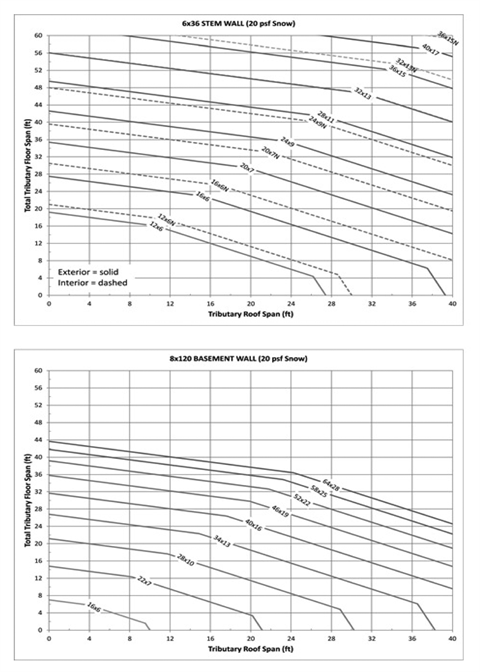
EXCEPTION: | Light-frame construction shall be permitted to have minimum footing size in accordance with Figures R403.1.1(1) through R403.1.1(4) in lieu of that determined by Table R403.1(1). |
Figure R403.1.1(1)
Alternative Minimum Footing Size for Light-Frame Construction a,b,c,d,e,f,g,h,i
20 PSF Snow Load
 |
Notes: | a | The minimum footing size is based on the following assumptions: Material weights per Section R301.2.2.2.1 and soil density = 120 pcf. Wood-framed walls = 10 foot; crawlspace stem wall = 6 inches × 36 inches; basement wall = 8 inches × 120 inches. Total load (TL) equal to the maximum of three load combinations: LC1=D+L, LC2=D+S and LC3=D=0.75(L+S), where D=dead load, L=live load, S=snow load. TL=max (LC1, LC2, LC3). |
b | Use tributary span of floor and roof. Figure may be used to size exterior and interior footings. | |
c | Add 4 feet to tributary floor span for each wood-framed wall above first level (i.e., 4 feet for 2-story, 8 feet for 3-story). | |
d | Multiply floor span by 1.25 for interior footings supporting continuous joists. | |
e | Multiply footing width by (1500 psf/capacity) for soil capacity other than 1500 psf. See Section R403.1.1 for thickness. | |
f | Dashed line may be used for interior footing size only. | |
g | Use footing size indicated on line above the span combination used. | |
h | For span combinations above the upper line, a design professional is required. | |
i | Interpolation between footing sizes is allowed. Extrapolation is not allowed. |
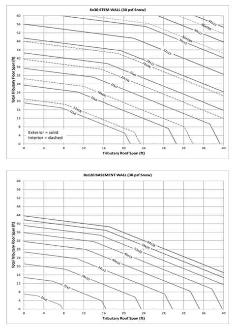
Figure R403.1.1(2)
Alternative Minimum Footing Size for Light-Frame Construction a,b,c,d,e,f,g,h,i
30 PSF Snow Load
 |
Notes: | a | The minimum footing size is based on the following assumptions: Material weights per Section R301.2.2.2.1 and soil density = 120 pcf. Wood-framed walls = 10 foot; crawlspace stem wall = 6 inches × 36 inches; basement wall = 8 inches × 120 inches. Total load (TL) equal to the maximum of three load combinations: LC1=D+L, LC2=D+S and LC3=D=0.75(L+S), where D=dead load, L=live load, S=snow load. TL=max (LC1, LC2, LC3). |
b | Use tributary span of floor and roof. Figure may be used to size exterior and interior footings. | |
c | Add 4 feet to tributary floor span for each wood-framed wall above first level (i.e., 4 feet for 2-story, 8 feet for 3-story). | |
d | Multiply floor span by 1.25 for interior footings supporting continuous joists. | |
e | Multiply footing width by (1500 psf/capacity) for soil capacity other than 1500 psf. See Section R403.1.1 for thickness. | |
f | Dashed line may be used for interior footing size only. | |
g | Use footing size indicated on line above the span combination used. | |
h | For span combinations above the upper line, a design professional is required. | |
i | Interpolation between footing sizes is allowed. Extrapolation is not allowed. |
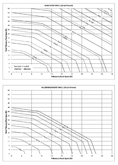
Figure R403.1.1(3)
Alternative Minimum Footing Size for Light-Frame Construction a,b,c,d,e,f,g,h,i
50 PSF Snow Load
 |
Notes: | a | The minimum footing size is based on the following assumptions: Material weights per Section R301.2.2.2.1 and soil density = 120 pcf. Wood-framed walls = 10 foot; crawlspace stem wall = 6 inches × 36 inches; basement wall = 8 inches × 120 inches. Total load (TL) equal to the maximum of three load combinations: LC1=D+L, LC2=D+S and LC3=D=0.75(L+S), where D=dead load, L=live load, S=snow load. TL=max (LC1, LC2, LC3). |
b | Use tributary span of floor and roof. Figure may be used to size exterior and interior footings. | |
c | Add 4 feet to tributary floor span for each wood-framed wall above first level (i.e., 4 feet for 2-story, 8 feet for 3-story). | |
d | Multiply floor span by 1.25 for interior footings supporting continuous joists. | |
e | Multiply footing width by (1500 psf/capacity) for soil capacity other than 1500 psf. See Section R403.1.1 for thickness. | |
f | Dashed line may be used for interior footing size only. | |
g | Use footing size indicated on line above the span combination used. | |
h | For span combinations above the upper line, a design professional is required. | |
i | Interpolation between footing sizes is allowed. Extrapolation is not allowed. |
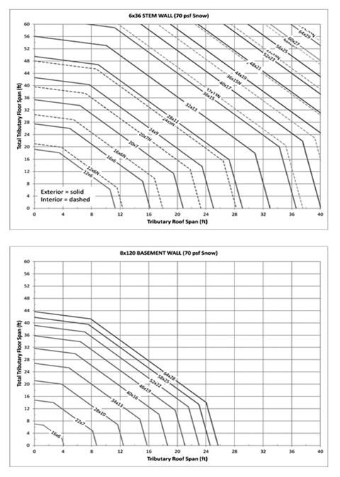
Figure R403.1.1(4)
Alternative Minimum Footing Size for Light-Frame Construction a,b,c,d,e,f,g,h,i
70 PSF Snow Load
 |
Notes: | a | The minimum footing size is based on the following assumptions: Material weights per Section R301.2.2.2.1 and soil density = 120 pcf. Wood-framed walls = 10 foot; crawlspace stem wall = 6 inches × 36 inches; basement wall = 8 inches × 120 inches. Total load (TL) equal to the maximum of three load combinations: LC1=D+L, LC2=D+S and LC3=D=0.75(L+S), where D=dead load, L=live load, S=snow load. TL=max (LC1, LC2, LC3). |
b | Use tributary span of floor and roof. Figure may be used to size exterior and interior footings. | |
c | Add 4 feet to tributary floor span for each wood-framed wall above first level (i.e., 4 feet for 2-story, 8 feet for 3-story). | |
d | Multiply floor span by 1.25 for interior footings supporting continuous joists. | |
e | Multiply footing width by (1500 psf/capacity) for soil capacity other than 1500 psf. See Section R403.1.1 for thickness. | |
f | Dashed line may be used for interior footing size only. | |
g | Use footing size indicated on line above the span combination used. | |
h | For span combinations above the upper line, a design professional is required. | |
i | Interpolation between footing sizes is allowed. Extrapolation is not allowed. |