(1) Manufacturing wire rope slings.
(a) Wire rope slings must be made from new or unused regular lay wire rope. The wire rope must be manufactured and tested in accordance with ASTM A 1023-02 and ASTM A 586.
(b) The following fabrication methods must be used to make wire rope slings:
(i) Hand splicing;
(ii) Turnback eye;
(iii) Return loop;
(iv) Flemish eye mechanical splicing;
(v) Poured or swaged socketing.
(c) Wire rope slings must have a design factor of 5.
(d) Wire rope slings must meet the requirements in Table 16.
(e) Using any of the following when making wire rope slings is prohibited:
(i) Rotation resistant wire rope;
(ii) Malleable cast iron clips;
(iii) Knots;
(iv) Wire rope clips, unless:
• The application of the sling prevents using prefabricated slings;
• The specific application is designed by a qualified person.
(f) You must install and maintain wire rope clips, if used, in accordance with the recommendations of the clip manufacturer or a qualified person, or in accordance with the provisions of ASME B30.26-2010.
(g) You must not use slings made with wire rope clips as a choker hitch.
Note: | If using wire rope clips under these conditions, follow the guidance given in Table 15. |
Table 15
Number, Torque Values, and Turn Back Requirements for U-Bolt Wire Rope Clips | Number, Torque Values and Turn Back Requirements for Double Saddle (Fist Grip) Wire Rope Clips | ||||||
Clip & Wire Rope Size (inches) | Min. No. of Clips | Amount of Rope Turn Back in Inches | *Torque inFt. Lbs. | Clip & Wire Rope Size (inches) | Min. No. of Clips | Amount of Rope Turn Back in Inches | *Torque in Ft. Lbs. |
1/8 | 2 | 3-1/4 | 4.5 | 3/16-1/4 | 2 | 4 | 30 |
3/16 | 2 | 3-3/4 | 7.5 | 5/16 | 2 | 5 | 30 |
1/4 | 2 | 4-3/4 | 15 | 3/8 | 2 | 5-1/4 | 45 |
5/16 | 2 | 5-1/4 | 30 | 7/16 | 2 | 6-1/2 | 65 |
3/8 | 2 | 6-1/2 | 45 | 1/2 | 3 | 11 | 65 |
7/16 | 2 | 7 | 65 | 9/16 | 3 | 12-3/4 | 130 |
1/2 | 3 | 11-1/2 | 65 | 5/8 | 3 | 13-1/2 | 130 |
9/16 | 3 | 12 | 95 | 3/4 | 4 | 16 | 225 |
5/8 | 3 | 12 | 95 | 7/8 | 4 | 26 | 225 |
3/4 | 4 | 18 | 130 | 1 | 5 | 37 | 225 |
7/8 | 4 | 19 | 225 | 1-1/8 | 5 | 41 | 360 |
1 | 5 | 26 | 225 | 1-1/4 | 6 | 55 | 360 |
1-1/8 | 6 | 34 | 225 | 1-3/8 | 6 | 62 | 500 |
1-1/4 | 7 | 44 | 360 | 1-1/2 | 7 | 78 | 500 |
1-3/8 | 7 | 44 | 360 | ||||
1-1/2 | 8 | 54 | 360 | ||||
1-5/8 | 8 | 58 | 430 | ||||
1-3/4 | 8 | 61 | 590 | ||||
2 | 8 | 71 | 750 | ||||
2-1/4 | 8 | 73 | 750 | ||||
2-1/2 | 9 | 84 | 750 | ||||
2-3/4 | 10 | 100 | 750 | ||||
3 | 10 | 106 | 1200 | ||||
3-1/2 | 12 | 149 | 1200 | ||||
* | The tightening torque values shown are based upon the threads being clean, dry, and free of lubrication. |
Table 16
Wire Rope Sling Configuration Requirements
If you have: | Then you need: | |
• | Slings made of rope with 6x19 and 6x36 classification. | A minimum clear length of rope 10 times the rope diameter between splices, sleeves, or end fittings (see Figure 15, Minimum Sling Length) unless approved by a qualified person. |
• | Cable laid slings. | |
• | Braided slings. | A minimum clear length of rope 40 times the component rope diameter between the loops or end fittings (see Figure 16, Minimum Braided Sling Length) unless approved by a qualified person. |
• | Grommets and endless slings. | A minimum circumferential length of 96 times the body diameter of the grommet or endless sling unless approved by a qualified person. |
• | Other configurations. | Specific limitation data provided by a qualified person. These slings must meet all other requirements of ASME B30.9-2010. |
 |
Figure 15 Minimum Sling Length For rope with 6x19 and 6x36 classification or Cable Laid Slings |
 |
Figure 16 Minimum Braided Sling Length |
(2) Wire rope sling fittings.
(a) You must use fittings according to the fitting manufacturer's directions.
(b) Rate slings with the load capacity of the lowest rated component of the sling. For example, if you use fittings that are rated lower than the sling material itself, identify the sling with the lower rated capacity.
(c) Weld any end attachments, except covers to thimbles, before assembling the sling.
(3) Identification information. All wire rope slings must have legible identification information attached to the sling which includes the information below, see sample tag in Figure 17. For slings in use that are manufactured before the effective date of this rule, you must add the information below before use or at the time the periodic inspection is completed.
(a) Name or trademark of the manufacturer.
(b) Diameter or size.
(c) Rated loads for the types of hitches used and the angle that the load is based on.
(d) Number of legs, if more than one.
(e) Repairing agency, if the sling is ever repaired.
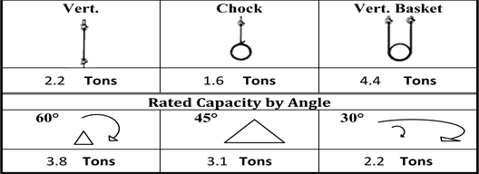 |
Figure 17 Sample Wire Rope Sling ID Tag |
Note: | Sample tag for a 1/2" single-leg sling 6x19 or 6x36 classification, extra improved plow steel (EIPS) grade fiber core (FC) wire rope with a mechanical splice (ton = 2,000 lb). |
(4) Inspection.
(a) A qualified person must inspect wire rope slings before their initial use, according to Table 17, both:
(i) When the sling is new; and
(ii) Whenever a repair, alteration, or modification has been done.
(b) A qualified person must perform a visual inspection for damage, each day or shift the wire rope sling is used:
(i) Include all fastenings and attachments;
(ii) Immediately remove any sling from service that is damaged beyond the criteria listed in Table 17; or
(iii) Remove fiber core wire rope slings that have been exposed to temperatures higher than 180 degrees Fahrenheit.
(c) A qualified person must perform periodic inspections on wire rope slings according to Table 17.
(5) Repair, alterations, or modifications.
(a) Repair wire rope slings as follows:
(i) Make sure slings are only repaired by the sling manufacturer or a qualified person;
(ii) Mark the sling to show the repairing agency;
(iii) You must not repair wire rope used in slings, you must replace wire rope. Only end attachments and fittings can be repaired on a wire rope sling.
(b) Modification or alterations to end attachments or fittings are considered as repairs and must conform to all other provisions of this part.
(c) Proof load test repaired slings according to the requirements in subsection (6) of this section.
(6) Proof load tests. Make sure the sling manufacturer or a qualified person proof load tests the following slings before initial use, according to Table 18:
(a) All repaired slings;
(b) All slings incorporating previously used or welded fittings;
(c) For single- or multiple-leg slings and endless slings, you must proof load each leg according to the requirements listed in Table 18 based on fabrication method. The proof load test must not exceed 50% of the component ropes' or structural strands' minimum breaking strength;
Table 17
Wire Rope Sling Inspection and Removal Criteria
Inspect wire rope slings for the following conditions: | Perform inspections: | |||
• | Missing or illegible sling identification. | |||
• | Severe localized abrasion or scraping. | |||
• | Kinking, crushing, birdcaging, or any other condition resulting in damage to the rope structure. | • | At least once a year for slings in normal service. | |
• | Evidence of heat damage. | • | At least once a quarter for slings in severe service. | |
• | Severe corrosion of the rope, end attachments, or fittings. | • | As recommended by a qualified person for slings in special service. | |
• | End attachments that are cracked, deformed, or worn to the extent that the strength of the sling is substantially affected. | |||
• | Broken wires: | |||
– | For strand-laid and single-part slings, 10 randomly distributed broken wires in one rope lay, or 5 broken wires in one strand in one rope lay; | |||
– | For cable-laid slings, 20 broken wires per lay; | |||
– | For 6-part braided slings, 20 broken wires per braid; | |||
– | For 8-part braided slings, 40 broken wires per braid. | |||
• | Hooks that have any of the following conditions: | |||
– | Any visibly apparent bend or twist from the plane of the unbent hook; | |||
– | Any distortion causing an increase in throat opening 5%, not to exceed one-quarter inch, or as recommended by the manufacturer; | |||
– | Wear exceeding 10%, of the original section dimension of the hook or its load pin, or as recommended by the manufacturer; | |||
– | Self-locking mechanism that does not lock. | |||
• | Other visible damage that raises doubt about the safety of the sling. | |||
Table 18
Wire Rope Sling Proof Load Test Requirements
Type of equipment: | Proof load test: | |
• | Mechanical splice slings. | Each leg to at least two times the single leg vertical hitch rated load. |
• | Swaged socket and poured socket slings. | Each leg to at least two times, but not more than 2 1/2, times the single-leg vertical hitch rated load. |
Note: For mechanical splice, swaged socket and poured socket slings follow the rope manufacturer's recommendations for proof load testing provided that it is within the above-specified proof load range, including (c) of this subsection. | ||
• | Hand tucked slings, if proof load tested. | To at least one, but not more than 1 1/4, times the single-leg vertical hitch rated load. |
(d) The proof load test for components (fittings) attached to single legs must meet the requirements in (c) of this subsection;
(e) Proof load testing for master links must be in accordance with Table 19.
Table 19
Proof Load Test for Master Links on Wire Rope Slings
• | Master links for two-leg bridle slings. | To at least 4 times the single-leg vertical hitch rated load. |
• | Master links for 3-leg bridle slings. | To at least 6 times the single-leg vertical hitch rated load. |
• | Master links for 4-leg bridle slings. | To at least 8 times the single-leg vertical hitch rated load. |
(7) Rated load. The term "rated capacity" is commonly used to describe rated load.
Note: | Rated loads are based on the following factors: |
• Strength of sling material; | |
• Design factor; | |
• Type of hitch; | |
• Angle of loading (see Figure 18, Angle of Loading); | |
• Diameter of curvature over which the sling is used (D/d) (see Figure 19, D/d ratio); | |
• Fabrication efficiency. |
(a) You must use wire rope slings within the rated loads shown in Tables 7 through 15 in ASME B30.9-2010. For angles that are not shown in these tables, either use the rated load for the next lower angle or have a qualified person calculate the rated load.
(b) Prohibit the use of horizontal sling angles less than 30 degrees unless recommended by the sling manufacturer or a qualified person. See Figure 18.
(c) Rated loads for slings used in a choker hitch must conform to the values shown in the above referenced tables, provided that the angle of choke is 120 degrees or greater. See Figure 20 and Table 20, Angle of Choke.
(d) Use either Figure 20 and Table 20, the manufacturer, or a qualified person to determine the rated load if the angle of choke in a choker hitch is less than 120 degrees.
(i) Inspect the entire length of the sling including splices, end attachments, and fittings.
(ii) Remove slings from use if any of the conditions in Table 17 are found.
(iii) Keep a record of the most recent periodic inspection available, including the condition of the sling.
Note: | An external code mark on the sling is an acceptable means of recording the inspection as long as the code can be traced back to a record. |
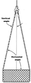 |
Figure 18 Angle of Loading |
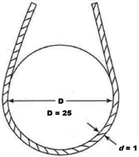 |
Figure 19 D/d Ratio |
Note: | When D is 25 times the component rope diameter (d) the D/d ratio is expressed as 25/1. |
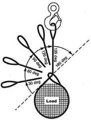 |
Figure 20 Angle of Choke |
Table 20
Angle of Choke
Angle of Choke, deg. | Rated Capacity, % |
Over 120 | 100 |
90 - 120 | 87 |
60 - 89 | 74 |
30 - 59 | 62 |
0 - 29 | 49 |
Note: Percent of sling rated capacity in a choker hitch. | |
(8) Use of wire rope slings.
(a) Hitch the slings in a way that provides control of the load.
(b) Shorten or adjust slings using only the methods approved by the manufacturer or qualified person.
• Do not shorten or lengthen by knotting, twisting, or by wire rope clips.
(c) Keep all parts of the human body from between the sling and the load, crane, or hoist hook.
(d) You must cover or blunt protruding ends of strands in splices on slings and bridles.
(e) You must not pull a sling from under a load when the load is resting on the sling.
(f) Prohibit all of the following:
(i) Intentional shock loading;
(ii) Avoid twisting and kinking.
(g) Decrease the rated load of the sling when D/d ratios (Figure 19) smaller than 25 to one. Consult the sling manufacturer for specific data or refer to the Wire Rope Sling User's Manual (wire rope technical board).
(h) Follow Table 21, Use of Wire Rope Slings or Clips, when using any of the identified wire rope slings or clips.
(i) You must protect slings in contact with edges, corners, or protrusions with a material of sufficient strength, thickness, and construction to prevent damage to the sling. See Figure 14.
Table 21
Use of Wire Rope Slings or Clips
If you are using: | Then: |
Single leg slings used with multiple-leg slings. | Make sure the rating shown is not exceeded in any leg of the multiple-leg sling. |
Hand tucked slings are used in a single leg vertical lift. | Do not allow the sling or load to rotate. |
Slings made with wire rope clips. | Must not be used as a choker hitch. |
Use only U-bolt wire rope clips that are made of drop-forged steel. | |
U-bolt wire rope clips. | Follow Table 15 for the number and spacing of the clips. |
Apply the U-bolt so the "U" section is in contact with the dead end of the rope (see Figure 21, Installation and Loading). |
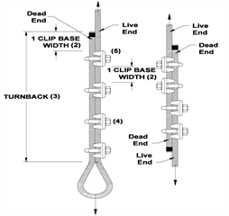 |
Figure 21 Installation and Loading |
Proper Installation Requires | |
• Correct number of clips for wire rope size | |
• Correct spacing of clips | |
• Correct turnback length | |
• Correct torque on nuts | |
• Correct orientation of saddle on live end |