R403.1.1 Minimum size. The minimum width, W, and thickness, T, for concrete footings shall be in accordance with Tables R403.1(1) through R403.1(3) and Figure R403.1(1) or R403.1.3, as applicable. The footing width shall be based on the load-bearing value of the soil in accordance with Table R401.4.1. Footing projections, P, shall be not less than 2 inches (51 mm) and shall not exceed the thickness of the footing. Footing thickness and projection for fireplaces shall be in accordance with Section R1001. The size of footings supporting piers and columns shall be based on the tributary load and allowable soil pressure in accordance with Table R401.4.1. Footings for wood foundations shall be in accordance with the details set forth in Section R403.2, and Figures R403.1(2) and R403.1(3).
EXCEPTION: | Light-frame construction shall be permitted to have minimum footing size in accordance with Figures R403.1.1(1) through R403.1.1(4) in lieu of that determined by Table R403.1(1). |
Figure R403.1.1(1)
Alternative Minimum Footing Size for Light-Frame Construction a,b,c,d,e,f,g,h,i
20 PSF Snow Load
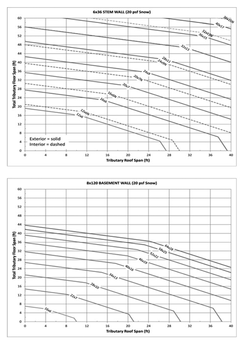 |
Notes: | a | The minimum footing size is based on the following assumptions: Material weights per Section R301.2.2.2.1 and soil density = 120 pcf. Wood framed walls = 10 foot; crawlspace stem wall = 6 inches × 36 inches; basement wall = 8 inches × 120 inches. Total load (TL) equal to the maximum of three load combinations: LC1=D+L, LC2=D+S and LC3=D=0.75(L+S), where D=dead load, L=live load, S=snow load. TL=max (LC1, LC2, LC3). |
b | Use tributary span of floor and roof. Figure may be used to size exterior and interior footings. | |
c | Add 4 feet to tributary floor span for each wood framed wall above first level (i.e., 4' for 2-story, 8' for 3-story). | |
d | Multiply floor span by 1.25 for interior footings supporting continuous joists. | |
e | Multiply footing width by (1500 psf/capacity) for soil capacity other than 1500 psf. See Section R403.1.1 for thickness. | |
f | Dashed line may be used for interior footing size only. | |
g | Use footing size indicated on line above the span combination used. | |
h | For span combinations above the upper line, a design professional is required. | |
i | Interpolation between footing sizes is allowed. Extrapolation is not allowed. |
Figure R403.1.1(2)
Alternative Minimum Footing Size for Light-Frame Construction a,b,c,d,e,f,g,h,i
30 PSF Snow Load
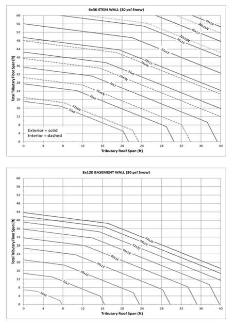 |
Notes: | a | The minimum footing size is based on the following assumptions: Material weights per Section R301.2.2.2.1 and soil density = 120 pcf. Wood framed walls = 10 foot; crawlspace stem wall = 6 inches × 36 inches; basement wall = 8 inches × 120 inches. Total load (TL) equal to the maximum of three load combinations: LC1=D+L, LC2=D+S and LC3=D=0.75(L+S), where D=dead load, L=live load, S=snow load. TL=max (LC1, LC2, LC3). |
b | Use tributary span of floor and roof. Figure may be used to size exterior and interior footings. | |
c | Add 4 feet to tributary floor span for each wood framed wall above first level (i.e., 4' for 2-story, 8' for 3-story). | |
d | Multiply floor span by 1.25 for interior footings supporting continuous joists. | |
e | Multiply footing width by (1500 psf/capacity) for soil capacity other than 1500 psf. See Section R403.1.1 for thickness. | |
f | Dashed line may be used for interior footing size only. | |
g | Use footing size indicated on line above the span combination used. | |
h | For span combinations above the upper line, a design professional is required. | |
i | Interpolation between footing sizes is allowed. Extrapolation is not allowed. |
Figure R403.1.1(3)
Alternative Minimum Footing Size for Light-Frame Construction a,b,c,d,e,f,g,h,i
50 PSF Snow Load
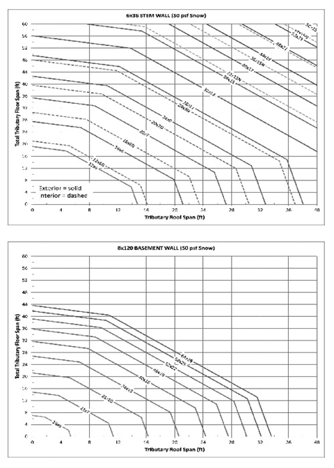 |
Notes: | a | The minimum footing size is based on the following assumptions: Material weights per Section R301.2.2.2.1 and soil density = 120 pcf. Wood framed walls = 10 foot; crawlspace stem wall = 6 inches × 36 inches; basement wall = 8 inches × 120 inches. Total load (TL) equal to the maximum of three load combinations: LC1=D+L, LC2=D+S and LC3=D=0.75(L+S), where D=dead load, L=live load, S=snow load. TL=max (LC1, LC2, LC3). |
b | Use tributary span of floor and roof. Figure may be used to size exterior and interior footings. | |
c | Add 4 feet to tributary floor span for each wood framed wall above first level (i.e., 4' for 2-story, 8' for 3-story). | |
d | Multiply floor span by 1.25 for interior footings supporting continuous joists. | |
e | Multiply footing width by (1500 psf/capacity) for soil capacity other than 1500 psf. See Section R403.1.1 for thickness. | |
f | Dashed line may be used for interior footing size only. | |
g | Use footing size indicated on line above the span combination used. | |
h | For span combinations above the upper line, a design professional is required. | |
i | Interpolation between footing sizes is allowed. Extrapolation is not allowed. |
Figure R403.1.1(4)
Alternative Minimum Footing Size for Light-Frame Construction a,b,c,d,e,f,g,h,i
70 PSF Snow Load
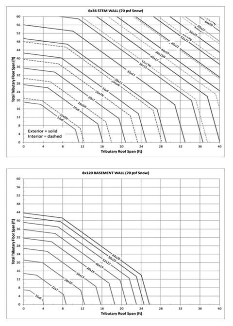 |
Notes: | a | The minimum footing size is based on the following assumptions: Material weights per Section R301.2.2.2.1 and soil density = 120 pcf. Wood framed walls = 10 foot; crawlspace stem wall = 6 inches × 36 inches; basement wall = 8 inches × 120 inches. Total load (TL) equal to the maximum of three load combinations: LC1=D+L, LC2=D+S and LC3=D=0.75(L+S), where D=dead load, L=live load, S=snow load. TL=max (LC1, LC2, LC3). |
b | Use tributary span of floor and roof. Figure may be used to size exterior and interior footings. | |
c | Add 4 feet to tributary floor span for each wood framed wall above first level (i.e., 4' for 2-story, 8' for 3-story). | |
d | Multiply floor span by 1.25 for interior footings supporting continuous joists. | |
e | Multiply footing width by (1500 psf/capacity) for soil capacity other than 1500 psf. See Section R403.1.1 for thickness. | |
f | Dashed line may be used for interior footing size only. | |
g | Use footing size indicated on line above the span combination used. | |
h | For span combinations above the upper line, a design professional is required. | |
i | Interpolation between footing sizes is allowed. Extrapolation is not allowed. |
R403.1.6 Foundation anchorage. Wood sill plates and wood walls supported directly on continuous foundations shall be anchored to the foundation in accordance with this section.
Cold-formed steel framing shall be anchored directly to the foundation or fastened to wood sill plates in accordance with Section R505.3.1 or R603.3.1, as applicable. Wood sill plates supporting cold-formed steel framing shall be anchored to the foundation in accordance with this section.
Wood sole plates at all exterior walls on monolithic slabs, wood sole plates of braced wall panels at building interiors on monolithic slabs and all wood sill plates shall be anchored to the foundation with minimum 1/2-inch-diameter (12.7 mm) anchor bolts spaced not greater than 6 feet (1829 mm) on center or approved anchors or anchor straps spaced as required to provide equivalent anchorage to 1/2-inch-diameter (12.7 mm) anchor bolts. Bolts shall extend not less than 7 inches (178 mm) into concrete or grouted cells of concrete masonry units. The bolts shall be located in the middle third of the width of the plate. A nut and washer shall be tightened on each anchor bolt. There shall be not fewer than two bolts per plate section with one bolt located not more than 12 inches (305 mm) or less than seven bolt diameters from each end of the plate section. Interior bearing wall sole plates on monolithic slab foundation that are not part of a braced wall panel shall be positively anchored with approved fasteners. Sill plates and sole plates shall be protected against decay and termites where required by Sections R317 and R318. Anchor bolts shall be permitted to be located while concrete is still plastic and before it has set. Where anchor bolts resist placement or the consolidation of concrete around anchor bolts is impeded, the concrete shall be vibrated to ensure full contact between the anchor bolts and concrete.
EXCEPTIONS: | 1. Walls 24 inches (610 mm) total length or shorter connecting offset braced wall panels shall be anchored to the foundation with not fewer than one anchor bolt located in the center third of the plate section and shall be attached to adjacent braced wall panels at corners as shown in Item 9 of Table R602.3(1). |
2. Connection of walls 12 inches (305 mm) total length or shorter connecting offset braced wall panels to the foundation without anchor bolts shall be permitted. The wall shall be attached to adjacent braced wall panels at corners as shown in Item 9 of Table R602.3(1). |
R404.1.3.3.6 Form materials and form ties. Forms shall be made of wood, steel, aluminum, plastic, a composite of cement and foam insulation, a composite of cement and wood chips, or other approved material suitable for supporting and containing concrete. Forms shall be positioned and secured before placing concrete and shall provide sufficient strength to contain concrete during the concrete placement operation. Form ties shall be steel, solid plastic, foam plastic, a composite of cement and wood chips, a composite of cement and foam plastic, or other suitable material capable of resisting the forces created by fluid pressure of fresh concrete.