WSR 22-17-148
PROPOSED RULES
BUILDING CODE COUNCIL
[Filed August 23, 2022, 4:00 p.m.]
Original Notice.
Preproposal statement of inquiry was filed as WSR 22-05-043.
Title of Rule and Other Identifying Information: Chapter 51-51 WAC, Adoption and amendment of the 2021 International Residential Code.
Hearing Location(s): On September 30, 2022, at 10:00 a.m., at 129 North 2nd Street, Yakima, WA 98901; or on October 14, 2022, at 10:00 a.m., at 1500 Jefferson Street S.E., Olympia, WA 98504. Please access the meetings in-person, or via Zoom or conference call. The Zoom link and phone are provided in the agenda at sbcc.wa.gov.
Date of Intended Adoption: November 4, 2022.
Submit Written Comments to: State Building Code Council (SBCC), 1500 Jefferson Street S.E., Olympia, WA 98504, email sbcc@des.wa.gov, by October 14, 2022.
Assistance for Persons with Disabilities: Contact Annette Haworth, phone 360-407-9255, email sbcc@des.wa.gov, by September 16, 2022.
Purpose of the Proposal and Its Anticipated Effects, Including Any Changes in Existing Rules: The proposed rule adopts the 2021 edition of the International Residential Code (IRC), published by the International Code Council (ICC), with state amendments to incorporate proposed changes as adopted by SBCC. The rules will provide increased clarity and life safety measures for building construction in Washington state.
SUMMARY OF PROPOSED CHANGES
2021 IRC Amendments to Chapter 51-51 WAC
WAC | Section | Changes in 2021 | Rationale/Discussion |
WAC 51-51-003 | | Replaces 2018 with 2021. | Refers to the current model code. |
WAC 51-51-008 | | Modifies the implementation date. | The modification changes the implementation date to July 1, 2023. |
WAC 51-51-01010 | R101; R101.2 | 1. Corrects the section number and the title. 2.Corrects references in exception 1, and adds exceptions 4, 5, and 6 to align with model code language. The existing amendment is exception 2 and the references to Appendix U instead of Section R2904. | Modifications are necessary to align with the model code language. |
WAC 51-51-0102 | R102.5 | 1. Deletes Appendix U from Exception 1. 2. Adds Appendix U to Exception 2. 3. Adds title "Tiny Homes" to Appendix Q. | Modifications are necessary to correct a conflict with WAC 51-51-003. |
R102.7.1 | 1. Replaces the first sentence of the existing amendment. 2. Adds new model code language. | The modifications to this existing amendment incorporate changes to the model code, and adds language part of Proposal 21-GP2-053R. Proposal 21-GP2-053R adds language to Sections R102.7.1, R202, R310.5, and new Chapter 44 Existing Buildingsand Structures. (See rationale for Chapter 44 for more details.) |
WAC 51-51-0106 | R106 | Removes the state amendment and saves WAC 51-51-0106 as reserved. | The existing amendment is no longer needed; it is addressed in the model code. |
WAC 51-51-0202 | R202 | 1. Deletes the definition for "Balanced whole house ventilation." 2. Deletes the definition for "Battery system, stationary storage." 3. Relocates the definition for "Building, existing," after the definition of "Building." 4. Adds a definition for "Enclosed kitchen." 5. Deletes the definition for "Energy storage systems (ESS)." 6. Adds a definition for "Loft." 7. Deletes the definition for "Lot." 8. Deletes the definition for "Mixed ventilation zone." 9. Deletes the definition for "Sleeping loft." 10. Deletes the definition for "Townhouse." 11. Deletes the definition for "Whole house ventilation system." | 1. The definition is no longer needed. It is addressed in the model code. Two new definitions - "Balanced Ventilation" and "Balanced Ventilation System," were added to 2021 IBC; the IRC TAG recommended adoption of model code definitions. In addition, the same information is contained in Section M1505.4.1.4. 2. This definition doesn't exist in the model code; there is no need for the existing amendment. 3. The existing definition is currently out of order. 4. The term "Enclosed kitchen" is used in the proposed language in Section M1503.3 and Table M1505.4.4.1 (21-GP2-062). 5. The definition is no longer needed; it is addressed in the model code. 6. The term "Loft." is used in the proposed language in Section R333 (21-GP2-099R). It replaces the defined term "Sleeping loft." 7. The definition is no longer needed; it is addressed in the model code. 8. This definition doesn't exist in the model code; there is no need for the existing amendment. 9. See item 6 above. 10. The definition is no longer needed; it is addressed in the model code. 11. The definition is no longer needed; it is addressed in the model code. |
WAC 51-51-0301 | R301 | Adds Section R301 to the title. | Editorial modification. |
R301.2.2.10 | New section in WAC. Amends the model code language by replacing the reference to Section P2801.8 with a reference to Uniform Plumbing Code (UPC) Section 507.1. | The new amendment is necessary to provide a correct reference to UPC. The International Plumbing Code is not adopted in Washington state. |
R301.5 Table R301.5 | Incorporates changes in the model code. | Incorporates changes in the model code in the table and footnotes a, c, d, h, and i. The existing amendment is footnote i, which is changed to footnote j. |
WAC 51-51-0302 | R302.2.1 | Deletes the existing amendment. | The existing amendment is no longer needed; it is addressed in the model code. |
R302.2.2 | The existing amendment is modified to incorporate model code changes. | The existing amendment is modified to incorporate model code changes. |
R302.3.1 | Adds a title and Exception 2. | The exception further clarifies when two-family dwelling shall be determined and required to have a separation wall and when it may be exempt from the separation requirements of Section R302.3. The intent has always been for only existing single-family dwelling units to be allowed to add a second dwelling unit for mother-in-law units and not have it counted towards the unit count. This new exception further clarifies this. (21-GP2-044R) |
R302.3.2 | Adds a title. | The existing amendment has no title. |
R302.3.4 | New section. | This proposal recognizes that there may be a program necessity for the units to be interconnected. It addresses this condition by limiting the opening to a door located within the unit demising wall. In addition, the proposal maintains unit separation continuity with the minimum 45-minute fire-rating and self-closing device. The exception recognizes the reduced hazard when automatic sprinklers are installed by reducing the opening rating to 20-minutes. Currently, IRC is silent on when there are openings (doors) between units of a duplex. Some designers have begun designing duplexes with a door in the common fire-rated wall assembly to access both dwelling units. This code addition provides direction and clarity to both the designer and reviewer when this situation comes up to maintain the minimum fire-rating of the common wall assembly. (21-GP2-042) |
R302.3.5 R302.3.5.1 Table R302.3.5 | New sections. | Designers are incorporating shared accessory spaces such as a laundry facility, HVAC mechanical rooms, etc. within two-family dwellings. Currently, the code is silent on how to deal with such connected accessory spaces in two-family dwelling units. This proposal helps clarify the hazards from accessory spaces is no greater than a common garage and should therefore be treated similarly with garages. |
R302.4.1 | Deletes existing amendment. | The existing amendment is no longer needed; it is addressed in the model code. |
WAC 51-51-0303 | R303.5 | Deletes existing amendment. | The existing amendment is no longer needed; it is addressed in the model code. |
WAC 51-51-0309 | R309.6 R309.6.1 R309.6.2 | New sections. | New requirements for EV infrastructure pursuant to E2SHB 1287. (21-GP2-091R) |
WAC 51-51-03100 | R310.1 | Adds Exceptions 3, 3.1 and 3.2. | This proposal recognizes that privacy fences are commonly used to enclose yards and addresses the use of gates to provide egress from these enclosed yards. Gate hardware is commonly used to maintain security by restricting access into the yard while maintaining free egress for self-evacuating occupants. Securing the gate with a padlock or other locking device would require an occupant to have knowledge of the key location and have access to it during the emergency. At a minimum, this would create a delay in occupant self-evacuation and is unacceptable. This proposal also recognizes that window wells are another common object that may be located within the pathway, particularly in narrow side yards. Open window wells located in the path can create significant elevation changes that pose a hazard for self-evacuating occupants. Requiring a cover over the opening eliminates this hazard and maintains the required unobstructed path. (See detailed rationale here: 21-GP2-041R) |
R310.1.1 | Deletes existing amendment. | The existing amendment is no longer needed; it is addressed in the model code. |
R310.2.4 | Modifies the existing amendment. | Modification incorporates changes in the model code. |
R310.5 | New section is added to WAC to clarify that the model code requirements for replacement windows for emergency escape and rescue openings are not adopted. | Amended provisions are proposed for adoption in Chapter 44. (See rationale for Chapter 44) |
WAC 51-51-0311 | R311.4 | Modifies the exception. | This is part of Proposal #21-GP2-099R pertaining to lofts. (See rationale for Section R333.) |
R311.7.11 R311.7.12 | New sections. | This is part of Proposal #21-GP2-099R pertaining to lofts. (See rationale for Section R333.) |
R311.7.3 | Deletes existing amendment. | The existing amendment is no longer needed; it is addressed by the model code. |
WAC 51-51-0312 | R312.1.1 R312.1.2 | New sections. | This is part of Proposal #21-GP2-099R pertaining to lofts. (See rationale for Section R333) |
WAC 51-51-0313 | R313.2 | Modifies the existing amendment. | Modification incorporates changes in the model code. |
WAC 51-51-0314 | R314.3 | 1. Adds Exception 6. 2. Adds exception 7 and deletes sleeping lofts from item 1. | 1. Incorporates changes to the model code. 2. This is part of Proposal #21-GP2-099R pertaining to lofts. (See rationale for Section R333) |
WAC 51-51-0315 | R315.2 | | The existing amendment is no longer needed; it is addressed in the model code. |
WAC 51-51-0326 | R326.1 | Adds a new exception. | This is part of Proposal #21-GP2-099R pertaining to lofts. (See rationale for Section R333) |
R326.2 R326.3 R326.4 | Deletes the existing amendments. | The existing amendments are no longer needed; all three are addressed in the model code. |
WAC 51-51-0327 | R327 | 1. Deletes the existing amendment pertaining to sleeping lofts. 2. Replaces with the requirements for swimming pools, spas and hot tubs. | 1. This is part of Proposal #21-GP2-099R pertaining to lofts. (See rationale for Section R333) 2. The requirements for swimming pools, spas and hot tubs are currently in WAC 51-51-0328. The relocation is necessary to align with the model code renumbering. |
WAC 51-51-0328 | R328 | Deletes the existing amendment pertaining to swimming pools, spas and hot tubs. Replaces with the requirements for energy storage systems. | The requirements for energy storage systems are currently in WAC 51-51-0329. The relocation is necessary to align with the model code renumbering. There are modifications to the model code language pertaining to energy storage systems; only sections not addressed in the model code are relocated to WAC 51-51-0328. The relocation of the requirements for swimming pools, spas, and hot tubs is also necessary due to the model code renumbering. |
WAC 51-51-0329 | R329 | Removes the state amendment and saves WAC 51-51-0329 as reserved. | See the rationale for WAC 51-50-0328. |
WAC 51-51-0333 | R333 | New section pertaining to lofts. | This proposal introduces "lofts" into the residential code, aligning the 2021 Washington state residential code with the loft amendments approved by SBCC for inclusion in the 2021 WA State Building Code (WSBC). Sleeping lofts were introduced into the 2018 WA State Residential Code (WSRC), and this proposal expands on that concept. It is also similar to a proposal submitted by WABO's Technical Code Development Committee to the 2022 Group B code development cycle for inclusion in the 2024 IRC. Similar provisions will be in an appendix in the 2024 IBC. See detailed rationale here:21-GP2-099R |
WAC 51-51-0334 | R334 | New section. | The requirements for stationary fuel cell power systems are in Section R330. This proposal is intended to renumber Section R330 to R334, and not to modify the model code language. The renumbering provides convenience to the code users in Washington state. |
WAC 51-51-0403 | R403.1.1 | Modifies the existing amendment by incorporating model code language. | Modifications are necessary to align the existing amendment with the changes to the model code. |
R403.1.6 R403.1.3.3.6 | Deletes the existing amendment. | The existing amendment is no longer needed; it is addressed in the model code. |
WAC 51-51-0404 | R404 | Removes the state amendment and saves WAC 51-51-0404 as reserved. | The existing amendment is no longer needed; it is addressed in the model code. |
WAC 51-51-0408 | R408.2 | Modifies the existing amendment by incorporating model code language in the last sentence of the first paragraph. | Modifications are necessary to align the existing amendment with the changes to the model code. |
| R408.8 | Adds new section to WAC 51-51-408, specifying that Section R408.8 is not adopted. | The model code language pertaining to under-floor ventilation is not applicable in Washington state due to more restrictive requirements in other WAC sections. |
WAC 51-51-0507 | R507.1 | Deletes the existing amendment. | The existing amendment is no longer needed; it is addressed in the model code. |
Table R507.3.1 | Modifies the existing amendment. | Incorporates model code changes. |
R507.5 | New amendment specifying Tables R507.5(1) through R507.5(4) are not adopted. | The model code tables are not applicable in Washington state. The existing amendment (Table R507.5) contains the maximum deck beam span in Washington. |
Table R507.5 | Modifies the existing amendment. | Incorporates model code changes. |
WAC 51-51-0608 | R608 | Removes the state amendment and saves WAC 51-51-0608 as reserved. | The existing amendment is no longer needed; it is addressed in the model code. |
WAC 51-51-0703 | R703.2 R703.4 | Deletes the existing amendment. | The existing amendment is no longer needed; it is addressed in the model code. |
WAC 51-51-1503 | M1503.3 M1503.5 | New sections. | The new sections are part of Proposal #21-GP2-062R This proposal adds differentiated ventilation requirements of hood ranges based on fuel type to reduce personal exposure and health impacts from ranges. These requirements are based on research done by Lawrence Berkeley National Laboratory where they found that dwellings are currently not adequately ventilating their stoves, which can increase the risk of asthma for children living in these dwellings. |
WAC 51-51-1505 | M1505.1 | New section. | The new section is part of Proposal #21-GP2-008R The proposal is an option, for those seeking higher ventilation rates to further improve IAQ in accordance with ASHRAE Standard 62.2. Higher ventilation rates can dilute and thereby reduce indoor air pollutants beyond the current IRC-WA rate options. See detailed rationale here:21-GP2-008R |
| M1505.4.1.4 | Modifies the last sentence of the existing amendment. | This modification is part of Proposal #21-GP2-062R See rationale for WAC 51-51-1503. |
| M1505.4.3.2 | Changes the reference to Section M1505.4.3(2) | Renumbering is part of Proposal #21-GP2-062R. |
| M1505.4.4 | Changes the reference to Table M1505.4.4.1. | Renumbering is necessary due to Proposal #21-GP2-062R. |
| M1505.4.4.1 | Changes the reference to Table M1505.4.4.1; adds "timer controls" to the text. | Modifications are part of Proposal #21-GP2-062R |
| Table M1505.4.4.1 | Modifies the existing amendment. | This modification is part of Proposal #21-GP2-062R See rationale for WAC 51-51-1503. |
| M1505.4.4.2 | 1. Deletes the exception in Item 1. 2. In Item 2, changes the reference to Table M1505.4.4.1. 3. Modifies the language in Item 4. 4. Adds Item 5. 5. Modifies the exception in Item 5. | This modification is part of Proposal #21-GP2-062R See rationale for WAC 51-51-1503. |
| Table M1505.4.4.2 | Corrects the table number. | Renumbering is necessary to align with proposal 21-GP2-062R. |
| M1505.4.4.3 | New section. | This new section is part of Proposal #21-GP2-062R See rationale for WAC 51-51-1503. |
| Table M1505.4.4.3 | New table. | This new table is part of Proposal #21-GP2-062R See rationale for WAC 51-51-1503. |
| M1505.4.4.3.1 | New section. | This new section is part of Proposal #21-GP2-062R See rationale for WAC 51-51-1503. |
WAC 51-51-2101.7 | M2107 | Delete the existing amendment. | The existing amendment specifies that Section M2107 pertaining to prohibited tee applications is not adopted. The UPC TAG recommended adoption of the model code language. |
WAC 51-51-2103 | M2103.3 | Replace the reference to Section 605.3.1 with a reference to Section 605. | This modification is suggested by the UPC TAG and it is intended to provide convenience to the code user. |
WAC 51-51-2105 | M2105.14 | Replace the reference to Section 605.12.2 with a reference to Section 605. | This modification is suggested by the UPC TAG and it is intended to provide convenience to the code user. |
WAC 51-51-4400 | | Adds new referenced standards. | This modification is part of Proposal #21-GP2-062R See rationale for WAC 51-51-1503. |
WAC 51-51-4501 | Chapter 45 | Adds Chapter 45. | This modification is part of Proposal #21-GP2-053R This proposed code change takes Appendix Chapter J of the 2021 IRC and moves it into the body of the IRC code as a new Chapter 44. The Appendix Chapter was used as a base for development of the new body of the code chapter, with the new chapter further expanded to include requirements for additions and relocations. See detailed rationale here: 21-GP2-053R |
WAC 51-51-4502 |
WAC 51-51-4503 |
WAC 51-51-4504 |
WAC 51-51-4505 |
WAC 51-51-4506 |
WAC 51-51-60106 | Appendix T | Several modifications to the existing amendment. | As suggested by the IRC TAG, the proposed deletions and modifications are intended to align the existing amendments with the model code language. Sections proposed for deletion are addressed in the model code. There is no intended change in regulatory effect. |
WAC 51-51-60108 | Appendix Y | New appendix. | The intent of this new optional appendix is to reduce the amount of construction and demolition waste that goes to a landfill after leaving a construction site. For jurisdictions where material management is a priority, this language helps to increase the amount of material that is salvaged for reuse – or recycled. Two forms are a part of this code change proposal (the Salvage Assessment and Waste Diversion Report) which would need to be submitted to the local building department. See detailed rationale here: 21-GP2-092R |
WAC 51-51-60109 | Appendix Z | New appendix. | The intent of this new optional appendix is to reduce the amount of material that is destroyed when demolishing a building. Systematically removing materials, components, and systems of an existing building through the process of deconstruction, increases the amount of construction and demolition material that can be salvaged for reuse and recycled instead of going to a landfill. See detailed rationale here: 21-GP2-093R |
Note: Those not listed on the table above remain as adopted in 2018 IBC.
Rule is not necessitated by federal law, federal or state court decision.
Name of Proponent: SBCC, governmental.
Name of Agency Personnel Responsible for Drafting and Implementation: Stoyan Bumbalov, 1500 Jefferson Street S.E., Olympia, WA 98504, 360-407-9277; Enforcement: Local jurisdictions.
A school district fiscal impact statement is not required under RCW
28A.305.135.
A cost-benefit analysis is required under RCW
34.05.328. A preliminary cost-benefit analysis may be obtained by contacting Stoyan Bumbalov, 1500 Jefferson Street S.E., Olympia, WA 98504, phone 360-407-9277, email
sbcc@des.wa.gov.
This rule proposal, or portions of the proposal, is exempt from requirements of the Regulatory Fairness Act because the proposal:
Is exempt under RCW
19.85.025(3) as the rules are adopting or incorporating by reference without material change federal statutes or regulations, Washington state statutes, rules of other Washington state agencies, shoreline master programs other than those programs governing shorelines of statewide significance, or, as referenced by Washington state law, national consensus codes that generally establish industry standards, if the material adopted or incorporated regulates the same subject matter and conduct as the adopting or incorporating rule; rules only correct typographical errors, make address or name changes, or clarify language of a rule without changing its effect; and rule content is explicitly and specifically dictated by statute.
Explanation of exemptions: The proposed rule adopts by reference the 2021 IRC with new and existing amendments. Many of the existing amendments are modified to incorporate changes to the model codes or to clarify language. There are several significant changes to the model code with economic impact. However, the model code changes are exempt under RCW
19.85.025(3) and
34.05.310 (4)(c), and are not part of this report.
Scope of exemption for rule proposal:
Is partially exempt:
Explanation of partial exemptions: The proposed rule adopts by reference the 2021 IRC with new and existing amendments. Many of the existing amendments are modified to incorporate changes to the model codes or to clarify language. There are several significant changes to the model code with economic impact. However, the model code changes are exempt under RCW
19.85.025(3) and
34.05.310 (4)(c), and are not part of this report.
The proposed rule does impose more-than-minor costs on businesses.
Small Business Economic Impact Statement
There are costs imposed by the proposed rule, but the costs do not fall disproportionately on small businesses. The rule will not affect the distribution of impacted work, whether by small businesses or not, doing the work. The rule does not affect employment, reporting, or recordkeeping.
Description: SBCC is filing a proposed rule to adopt the 2021 edition of the IRC (chapter 51-51 WAC). Since 1985, SBCC has been responsible to update to new editions of the building code per RCW
19.27.074. IBC is updated every three years by ICC. The code development process conducted by the model code organization is open to all interest groups within the design and construction industry and from governmental organizations. See
www.iccsafe.org for more information about the model code development process. The administrative compliance requirements are under the authority of the local governments (RCW
19.27.050). Enforcement activities, including permit issuance, plan review/approval, and inspections occur at the local level. Requirements for construction documents submittal and other reporting mandates are determined by the local jurisdiction and are consistent with previously established policies. The proposed amendments to chapter 51-51 WAC include specific technical requirements for building construction to be consistent with national standards.
Professional Services: Washington has had a statewide building code in effect since 1974. The local enforcement authority having jurisdiction administers the codes through the building and/or fire departments. Administrative procedures for state building code compliance are established and will not be changed by the adoption of the 2021 building codes. Small businesses will employ the same types of professional services for the design and construction of buildings and systems to comply with the state building code. The proposed rule updates the state building code and does not require additional equipment, supplies, labor, or other services. Services needed to comply with the building code are existing within the construction industry as required by the local authority having jurisdiction.
Costs of Compliance for Businesses: The council is required to adopt and maintain the state building code, as provided in chapters
19.27, 19.27A, and
70.92 RCW, and the state legislature. The primary objective of the council is to encourage consistency in the building code throughout the state of Washington and to maintain the building code consistent with the state's interest as provided in RCW
19.27.020. An objective of statewide adoption is to minimize state amendments to the model codes. The council accepts the statewide code amendment proposal from stakeholders to amend IRC to meet the legislative goals. The statewide code adoption process is defined in chapter 51-04 WAC and the council bylaws. All proposals must be submitted in writing on the appropriate form with the indicated supporting documentation. Each proponent must identify where a proposed amendment has an economic impact, and estimate the costs and savings of the proposal on construction practices, users and/or the public, the enforcement community, and operation and maintenance.
The cost of compliance incurred by Washington businesses includes training and educational materials. The new 2021 IRC, 2021 IRC significant changes, and 2021 IRC study pack cost $215 + tax shipping and handling. The 2021 IRC is also available online at https://shop.iccsafe.org.
For the 2021 code adoption cycle, the council received 11 proposals. IRC technical advisory group (TAG) recommended approval of eight proposals as submitted or as modified. The council approved nine proposals to be included in the CR-102. Two proposals were identified by TAG as having a cost (increase) for compliance on businesses. However, proposal 21-GP2-091R (EV infrastructure) is driven by E2SHB 1287 and is exempt. Nevertheless, a preliminary cost-benefit analysis will be provided for this proposal. The council recommended filing the proposed rule to allow input through the public hearing process.
1. Section 302.3.4 (21-GP2-042): This proposal recognizes that there may be a program necessity for the units to be interconnected. It addresses this condition by limiting the opening to a door located within the unit demising wall. In addition, the proposal maintains unit separation continuity with the minimum 45-minute fire-rating and self-closing device. The exception recognizes the reduced hazard when automatic sprinklers are installed by reducing the opening rating to 20-minutes. Currently, IRC is silent on when there are openings (doors) between units of a duplex. Some designers have begun designing duplexes with a door in the common fire-rated wall assembly to access both dwelling units. This code addition provides direction and clarity to both the designer and reviewer when this situation comes up to maintain the minimum fire-rating of the common wall assembly.
The proponent states that the additional cost will be from the 45-minute fire-rated door that is required. Typical cost is between $400-$800 for a 45-minute fire-resistive door. It should also be noted that a one-hour fire-resistive wall assembly that are 4' x 8' panels will typically run $50-$75. The net cost of the door would therefore be in the $300-$700 range.
Loss of Sales or Revenue: The proposed rules make the state code for building construction consistent with national standards. Businesses with new products or updated test or design standards are recognized in the updated building code. The update will result in some cost outlay for some small businesses for specific building projects, for a transition period. Other small businesses would see an increase in revenue. The amendments to the building codes affect over 25,000 small businesses in the state, where construction activity occurs. The primary intent of the amendments is to improve the safety features in buildings and provide consistency and fairness across the state, for a predictable business environment. The amendments should result in enhanced safety and value in buildings.
Cost of Compliance for Small Businesses: Determine whether the proposed rule will have a disproportionate cost impact on small businesses, compare the cost of compliance for small businesses with the cost of compliance for the 10 percent of businesses that are the largest businesses. Most businesses affected by the updates to the building codes are small businesses; over 95 percent of those listed in the construction and related industries have under 50 employees. The costs per employee are comparable between the largest businesses and the majority of small businesses. The cost to comply with the updated codes is not a disproportionate impact on small businesses. Where the council found the cost of compliance for small businesses to be disproportionate, the proposed rule mitigates the cost. The proposed rules include a definition of small business and provide exceptions for compliance with the updated rule.
Reducing the Costs of the Rule on Small Businesses: SBCC conducted a detailed review process, including participation at the national code development hearings, to document significant economic impacts of the proposed code amendments.
List of Industries: Below is a list of industries required to comply with the building code:
Industry NAICS Code | NAICS Code Title | Minor Cost Estimate | 1% of Avg Annual Payroll | 0.3% of Avg Annual Gross Business Income |
236115 | New Single-Family Housing Construction (except For-Sale Builders) | $2,508.04 | $1,919.03 2020 Dataset pulled from USBLS | $2,508.04 2020 Dataset pulled from DOR |
236116 | New Multifamily Housing Construction (except For-Sale Builders) | $32,067.43 | $17,160.94 2020 Dataset pulled from USBLS | $32,067.43 2020 Dataset pulled from DOR |
236118 | Residential Remodelers | $1,457.74 | $1,457.74 2020 Dataset pulled from USBLS | $901.20 2020 Dataset pulled from DOR |
236210 | Industrial Building Construction | $59,169.45 | $59,169.45 2020 Dataset pulled from ESD | $53,925.71 2020 Dataset pulled from DOR |
236220 | Commercial and Institutional Building Construction | $41,552.81 | $18,126.81 2020 Dataset pulled from ESD | $41,552.81 2020 Dataset pulled from DOR |
238110 | Poured Concrete Foundation and Structure Contractors | $3,442.28 | $5,027.07 2019 Dataset pulled from CBP | $3,442.28 2020 Dataset pulled from DOR |
238120 | Structural Steel and Precast Concrete Contractors | $15,401.97 | $20,212.19 2019 Dataset pulled from CBP | $15,401.97 2020 Dataset pulled from DOR |
238130 | Framing Contractors | $2,234.30 | $3,139.71 2019 Dataset pulled from CBP | $2,234.30 2020 Dataset pulled from DOR |
238140 | Masonry Contractors | $1,900.60 | $3,582.13 2019 Dataset pulled from CBP | $1,900.60 2020 Dataset pulled from DOR |
238150 | Glass and Glazing Contractors | 5,255.36 | $9,574.95 2019 Dataset pulled from CBP | $5,255.36 2020 Dataset pulled from DOR |
238160 | Roofing Contractors | $3,589.99 | $5,007.86 2019 Dataset pulled from CBP | $3,589.99 2020 Dataset pulled from DOR |
238170 | Siding Contractors | $1,905.61 | $2,485.86 2019 Dataset pulled from CBP | $1,905.61 2020 Dataset pulled from DOR |
238190 | Other Foundation; Structure; and Building Exterior Contractors | $4,622.07 | $4,141.38 2019 Dataset pulled from CBP | $4,622.07 2020 Dataset pulled from DOR |
238210 | Electrical Contractors and Other Wiring Installation Contractors | $5,941.60 | $9,599.33 2019 Dataset pulled from CBP | $5,941.60 2020 Dataset pulled from DOR |
238220 | Plumbing; Heating; and Air-Conditioning Contractors | $5,353.76 | $11,047.00 2019 Dataset pulled from CBP | $5,353.76 2020 Dataset pulled from DOR |
238290 | Other Building Equipment Contractors | $4,335.21 | $16,142.07 2019 Dataset pulled from CBP | $4,335.21 2020 Dataset pulled from DOR |
238310 | Drywall and Insulation Contractors | $3,725.66 | $9,461.67 2019 Dataset pulled from CBP | $3,725.66 2020 Dataset pulled from DOR |
238990 | All Other Specialty Trade Contractors | $3,585.74 | $3,677.28 2019 Dataset pulled from CBP | $3,585.74 2020 Dataset pulled from DOR |
321213 | Engineered Wood Member (except Truss) Manufacturing | $44,480.76 | $44,480.76 2020 Dataset pulled from ESD | $41,772.84 2020 Dataset pulled from DOR |
321214 | Truss Manufacturing | $28,620.35 | $23,341.04 2020 Dataset pulled from ESD | $28,620.35 2020 Dataset pulled from DOR |
321219 | Reconstituted Wood Product Manufacturing | $30,305.17 | $10,139.90 2020 Dataset pulled from USBLS | $30,305.17 2020 Dataset pulled from DOR |
321911 | Wood Window and Door Manufacturing | $45,151.12 | $18,811.08 2020 Dataset pulled from ESD | $45,151.12 2020 Dataset pulled from DOR |
321992 | Prefabricated Wood Building Manufacturing | $5,391.09 | $5,391.09 2020 Dataset pulled from ESD | $4,888.53 2020 Dataset pulled from DOR |
327310 | Cement Manufacturing | $50,878.29 | $44,741.20 2020 Dataset pulled from ESD | $50,878.29 2020 Dataset pulled from DOR |
327320 | Ready-Mix Concrete Manufacturing | $64,317.30 | $46,126.21 2020 Dataset pulled from ESD | $64,317.30 2020 Dataset pulled from DOR |
327331 | Concrete Block and Brick Manufacturing | $15,030.60 | $15,030.60 2020 Dataset pulled from ESD | $10,431.02 2020 Dataset pulled from DOR |
332312 | Fabricated Structural Metal Manufacturing | $22,220.31 | $16,337.10 2020 Dataset pulled from USBLS | $22,220.31 2020 Dataset pulled from DOR |
332321 | Metal Window and Door Manufacturing | $26,369.28 | $14,505.40 2020 Dataset pulled from ESD | $26,369.28 2020 Dataset pulled from DOR |
332322 | Sheet Metal Work Manufacturing | $23,337.23 | $23,337.23 2020 Dataset pulled from ESD | $16,556.52 2020 Dataset pulled from DOR |
335121 | Residential Electric Lighting Fixture Manufacturing | $2,011.37 | $2,011.37 2020 Dataset pulled from USBLS | $1,502.01 2020 Dataset pulled from DOR |
335122 | Commercial; Industrial; and Institutional Electric Lighting Fixture Manufacturing | $6,357.34 | Redacted 2020 Dataset pulled from USBLS | $6,357.34 2020 Dataset pulled from DOR |
335129 | Other Lighting Equipment Manufacturing | $6,281.32 | $6,281.32 2020 Dataset pulled from ESD | $2,494.40 2020 Dataset pulled from DOR |
423720 | Plumbing and Heating Equipment and Supplies (Hydronics) Merchant Wholesalers | $24,486.53 | $16,589.10 2020 Dataset pulled from ESD | $24,486.53 2020 Dataset pulled from DOR |
541310 | Architectural Services | $9,221.65 | $9,221.65 2020 Dataset pulled from ESD | $3,738.99 2020 Dataset pulled from DOR |
541330 | Engineering Services | $14,801.92 | $14,801.92 2020 Dataset pulled from USBLS | $7,177.43 2020 Dataset pulled from DOR |
541350 | Building Inspection Services | $1,868.52 | $1,868.52 2020 Dataset pulled from ESD | $475.93 2020 Dataset pulled from DOR |
561621 | Security Systems Services (except Locksmiths) | $9,759.28 | $9,759.28 2020 Dataset pulled from ESD | $6,117.04 2020 Dataset pulled from DOR |
Estimate of the Number of Jobs That Will Be Created or Lost: The adoption of the latest code edition is not expected to significantly impact the number of jobs in the construction industry. These rules are likely to be job neutral overall, i.e., they will not result in any job gains or losses. The scheduled effective date of the new edition is July 1, 2021. Building permits issued prior to that date will be vested under the 2018 building code. Permits issued for projects under the 2021 code edition will generally start with the 2024 construction season.
A copy of the statement may be obtained by contacting Stoyan Bumbalov, 1500 Jefferson Street S.E., Olympia, WA 98504, phone 360-407-9277, email sbcc@des.wa.gov.
August 23, 2022
Tony Doan
Council Chair
OTS-4043.1
Chapter 51-51 WAC
STATE BUILDING CODE ADOPTION AND AMENDMENT OF THE ((2018))2021 EDITION OF THE INTERNATIONAL RESIDENTIAL CODE
AMENDATORY SECTION(Amending WSR 20-03-023, filed 1/6/20, effective 7/1/20)
WAC 51-51-003International Residential Code.
The ((2018))2021 edition of the International Residential Code as published by the International Code Council is hereby adopted by reference with the following additions, deletions, and exceptions: Provided that chapters 11 and 25 through 43 of this code are not adopted. Energy Code is regulated by chapter 51-11R WAC; Plumbing Code is regulated by chapter 51-56 WAC; Electrical Code is regulated by chapter 296-46B WAC or Electrical Code as adopted by the local jurisdiction. Appendix F, Radon Control Methods, Appendix Q, Tiny Homes, and Appendix U, Dwelling Unit Fire Sprinkler Systems, are included in adoption of the International Residential Code.
AMENDATORY SECTION(Amending WSR 21-11-066, filed 5/14/21, effective 6/14/21)
WAC 51-51-008Implementation.
The International Residential Code adopted by chapter 51-51 WAC shall become effective in all counties and cities of this state on ((February 1, 2021))July 1, 2023.
AMENDATORY SECTION(Amending WSR 20-03-023, filed 1/6/20, effective 7/1/20)
WAC 51-51-01010Section R101—Scope and general requirements.
R101.2 Scope. The provisions of the International Residential Code for One- and Two-Family Dwellings shall apply to the construction, alteration, movement, enlargement, replacement, repair, equipment, use and occupancy, location, removal and demolition of detached one- and two-family dwellings, adult family homes, and townhouses not more than three stories above grade plane in height with a separate means of egress and their accessory structures not more than three stories above grade plane in height.
EXCEPTIONS: | 1. Live/work units located in townhouses and complying with the requirements of Section ((419))508.5 of the International Building Code shall be permitted to be constructed in accordance with the International Residential Code for One- and Two-Family Dwellings. ((Fire suppression))An automatic sprinkler system required by Section ((419.5))508.5.7 of the International Building Code where constructed under the International Residential Code for One- and Two-Family Dwellings shall conform to Appendix U. |
| 2. Owner-occupied lodging houses with one or two guestrooms shall be permitted to be constructed in accordance with the International Residential Code forOne- and Two-Family Dwellings. |
| 3. Owner-occupied lodging homes with three to five guestrooms shall be permitted to be constructed in accordance with the International Residential Code for One- and Two-Family Dwellings where equipped with ((a))an automatic fire sprinkler system in accordance with Appendix U. |
| 4. A care facility with five or fewer persons receiving custodial care within a dwelling unit shall be permitted to be constructed in accordance with the International Residential Code for One- and Two-Family Dwellings where equipped with an automatic fire sprinkler system in accordance with Appendix U. |
| 5. A care facility with five or fewer persons receiving medical care within a dwelling unit shall be permitted to be constructed in accordance with the International Residential Code for One- and Two-Family Dwellings where equipped with an automatic fire sprinkler system in accordance with Appendix U. |
| 6. A care facility with five or fewer persons receiving care that are within a single-family dwelling shall be permitted to be constructed in accordance with the International Residential Code for One- and Two-Family Dwellings where equipped with an automatic fire sprinkler system in accordance with Appendix U. |
AMENDATORY SECTION(Amending WSR 20-21-041, filed 10/13/20, effective 11/13/20)
WAC 51-51-0102Section R102—Applicability.
R102.5 Appendices. Provisions in the appendices shall not apply unless specifically referenced in the adopting ordinance. An appendix adopted by a local jurisdiction shall not be effective unless approved by the state building code council pursuant to RCW
19.27.060 (1)(a).
EXCEPTIONS: | 1. The state building code council has determined that a local ordinance providing specifications for light straw-clay or strawbale construction, or requiring a solar-ready zone or requiring fire sprinklers in accordance with Appendix R, S, ((U)) or V of this chapter may be adopted by any local government upon notification of the council. |
| 2. Appendix F, Radon Control Methods, ((and)) Appendix Q, Tiny Homes, and Appendix U, Dwelling Unit Fire Sprinkler Systems, are included in adoption of the International Residential Code. |
R102.7.1 Additions, alterations or repairs. Additions, alterations ((or)), repairs ((to any structure)), or relocations shall be permitted to conform to the requirements of the provisions of Chapter 44 or shall conform to the requirements for ((a)) new structure without requiring the existing structure to comply with the requirements of this code, unless otherwise stated. Additions, alterations ((or)), repairs, and relocations shall not cause an existing structure to become ((unsafe or adversely affect the performance of the building))less compliant with the provisions of this code than the existing building or structure was prior to the addition, alteration, repair, or relocation. An existing building together with its additions shall comply with the height limits of this code. Where the alteration or addition causes the use or occupancy to be changed to one not within the scope of this code, the provisions of the International Existing Building Code shall apply.
EXCEPTIONS: | 1. Additions with less than 500 square feet of conditioned floor area are exempt from the requirements for Whole House Ventilation Systems, Section M1505.4. |
| 2. Additions or alterations to existing buildings which do not require the construction of foundations, crawlspaces, slabs or basements shall not be required to meet the requirements for radon protection in Section R332.1 and Appendix F. |
R102.7.2 Moved buildings. Buildings or structures moved into or within a jurisdiction shall comply with the provisions of this code, the International Building Code (chapter 51-50 WAC), the International Mechanical Code (chapter 51-52 WAC), the International Fire Code (chapter 51-54A WAC), the Uniform Plumbing Code and Standards (chapter 51-56 WAC), and the Washington State Energy Code (chapter 51-11R WAC) for new buildings or structures.
EXCEPTION: | Group R-3 buildings or structures are not required to comply if: |
| 1. The original occupancy classification is not changed; and |
| 2. The original building is not substantially remodeled or rehabilitated. For the purposes of this section a building shall be considered to be substantially remodeled when the costs of remodeling exceed 60 percent of the value of the building exclusive of the costs relating to preparation, construction, demolition or renovation of foundations. |
AMENDATORY SECTION(Amending WSR 20-03-023, filed 1/6/20, effective 7/1/20)
WAC 51-51-0106((Section 106—Construction documents.))Reserved.
((R106.1 Submittal documents. Submittal documents consisting of construction documents, and other data shall be submitted in two or more sets, or in a digital format where allowed by the building official, with each application for a permit. The construction documents shall be prepared by a registered design professional where required by the statutes of the jurisdiction in which the project is to be constructed. Where special conditions exist, the building official is authorized to require additional construction documents to be prepared by a registered design professional.
EXCEPTION: | The building official is authorized to waive the submission of construction documents and other data not required to be prepared by a registered design professional if it is found that the nature of the work applied for is such that reviewing of construction documents is not necessary to obtain compliance with this code.)) |
AMENDATORY SECTION(Amending WSR 21-12-102, filed 6/2/21, effective 7/3/21)
WAC 51-51-0202Section R202—Definitions.
ADULT FAMILY HOME. A dwelling, licensed by the state of Washington department of social and health services, in which a person or persons provide personal care, special care, room and board to more than one but not more than six adults who are not related by blood or marriage to the person or persons providing the services. An existing adult family home may provide services to up to eight adults upon approval from the department of social and health services in accordance with RCW
70.128.066.
((BALANCED WHOLE HOUSE VENTILATION. Balanced whole house ventilation is defined as any combination of concurrently operating residential unit mechanical exhaust and mechanical supply whereby the total mechanical exhaust airflow rate is within 10 percent or 5 cfm, whichever is greater, of the total mechanical supply airflow rate. Intermittent dryer exhaust, intermittent range hood exhaust, and intermittent toilet room exhaust airflow rates above the residential dwelling or sleeping unit minimum ventilation rate are exempt from the balanced airflow calculation.
BATTERY SYSTEM, STATIONARY STORAGE. This definition is not adopted.
BUILDING, EXISTING. A building or structure erected prior to the adoption of this code, or one that has passed a final inspection.))
BUILDING. Any one- or two-family dwelling or townhouse, or portion thereof used or intended to be used for human habitation, for living, sleeping, cooking or eating purposes, or any combination thereof, or any accessory structure.
BUILDING, EXISTING. A building or structure erected prior to the adoption of this code, or one that has passed a final inspection.
CHILD CARE, FAMILY HOME. A child care facility, licensed by Washington state, located in the dwelling of the person or persons under whose direct care and supervision the child is placed, for the care of twelve or fewer children, including children who reside at the home.
CHILD DAY CARE, shall, for the purposes of these regulations, mean the care of children during any period of a 24 hour day.
CONDITIONED SPACE. An area, room or space that is enclosed within the building thermal envelope and that is directly or indirectly heated or cooled. Spaces are indirectly heated or cooled where they communicate through openings with conditioned spaces, where they are separated from conditioned spaces by uninsulated walls, floors or ceilings, or where they contain uninsulated ducts, piping or other sources of heating or cooling.
DISTRIBUTED WHOLE HOUSE VENTILATION. A whole house ventilation system shall be considered distributed when it supplies outdoor air directly (not transfer air) to each dwelling or sleeping unit habitable space (living room, den, office, interior adjoining spaces or bedroom), and exhausts air from all kitchens and bathrooms directly outside.
DWELLING UNIT. A single unit providing complete independent living facilities for one or more persons, including permanent provisions for living, sleeping, eating, cooking and sanitation. Dwelling units may also include the following uses:
1. Adult family homes, foster family care homes and family day care homes licensed by the Washington state department of social and health services.
2. Offices, mercantile, food preparation for off-site consumption, personal care salons or similar uses which are conducted primarily by the occupants of the dwelling unit and are secondary to the use of the unit for dwelling purposes, and which do not exceed 500 square feet (46.4 m2).
EGRESS ROOF ACCESS WINDOW. A skylight or roof window designed and installed to satisfy the Emergency Escape and Rescue Opening requirements of Section R310.2.
((ENERGY STORAGE SYSTEMS (ESS). One or more devices, assembled together, capable of storing energy in order to supply electrical energy at a future time.))
ENCLOSED KITCHEN. A kitchen whose permanent openings to interior adjacent spaces do not exceed a total of 60 square feet (6 m2).
FIRE SEPARATION DISTANCE. The distance measured from the foundation wall or face of the wall framing, whichever is closer, to one of the following:
1. To the closest interior lot line; or
2. To the centerline of a street, an alley or public way; or
3. To an imaginary line between two buildings on the lot.
The distance shall be measured at a right angle from the wall.
FLOOR AREA. The area within the inside perimeter of exterior walls of the building. The floor area of a building, or portion thereof, not provided with surrounding exterior walls shall be the usable area under the horizontal projection of the roof or floor above.
LANDING PLATFORM. A landing provided as the top step of a stairway accessing a Sleeping Loft.
LOCAL EXHAUST. An exhaust system that uses one or more fans to exhaust air from a specific room or rooms within a residential dwelling or sleeping unit.
((LOT. A measured portion or parcel of land considered as a unit having fixed boundaries.))
LOFT. A space on an intermediate level or levels between the floor and ceiling of a dwelling or sleeping unit, open on one or more sides to the room or space in which the loft is located, and in accordance with Section R326.
LOT LINE. The line which bounds a plot of ground described as a lot in the title to the property.
((MIXED VENTILATION ZONE. This definition is not adopted.))
SALT WATER COASTAL AREA. Those areas designated as salt water coastal areas by the local jurisdiction.
((SLEEPING LOFT. A sleeping space on a floor level located more than 30 inches (726 mm) above the main floor and open to the main floor on one or more sides with a ceiling height of less than 6 feet 8 inches (2032 mm).))
SMALL BUSINESS. Any business entity (including a sole proprietorship, corporation, partnership or other legal entity) which is owned and operated independently from all other businesses, which has the purpose of making a profit, and which has fifty or fewer employees.
((TOWNHOUSE. A building that contains three or more attached townhouse units.))
TOWNHOUSE UNIT. A single-family dwelling unit in a townhouse that extends from foundation to roof and that has a yard or public way on not less than two sides that extends at least 50 percent of the length of each of these two sides.
((WHOLE HOUSE VENTILATION SYSTEM. A mechanical ventilation system, including fans, controls, and ducts, which replaces, by direct means, air from the habitable rooms with outdoor air.))
AMENDATORY SECTION(Amending WSR 20-03-023, filed 1/6/20, effective 7/1/20)
WAC 51-51-0301Section R301—Design criteria.
R301.2 Climatic and geographic design criteria. Buildings shall be constructed in accordance with the provisions of this code as limited by the provisions of this section. Additional criteria shall be established by the local jurisdiction and set forth in Table R301.2(1). The local jurisdiction shall designate the salt water coastal areas within their jurisdiction.
R301.2.2.10 Anchorage of water heaters. In Seismic Design Categories D0, D1 and D2, and in townhouses in Seismic Design Category C, water heaters and thermal storage units shall be anchored against movement and overturning in accordance with Section M1307.2 or the Uniform Plumbing Code Section 507.1.
R301.5 Live load. The minimum uniformly distributed live load shall be as provided in Table R301.5.
TABLE R301.5
MINIMUM UNIFORMLY DISTRIBUTED LIVE LOADS
(in pounds per square foot)
| Use | ((Live))Uniform Load (psf) | Concentrated Load (lb) | |
| Uninhabitable attics without storageb | 10 | - | |
| Uninhabitable attics with limited storageb, g | 20 | - | |
| Habitable attics and attics served with fixed stairs | 30 | - | |
| Balconies (exterior) and deckse | 60((i))j | - | |
| Fire escapes | 40 | - | |
| Guards ((and handrailsd)) | ((200h)) - | 200h,i | |
| Guard in-fill componentsf | ((50h)) - | 50h | |
| Handraild | - | 200h | |
| Passenger vehicle garagesa | 50a | 2,000h | |
| ((Rooms))Areas other than sleeping ((rooms))areas | 40 | - | |
| Sleeping ((rooms))areas | 30 | - | |
| Stairs | 40c | 300c | |
For SI: 1 pound per square foot = 0.0479 kPa, 1 square inch = 645 mm, 1 pound = 4.45 N |
a. | Elevated garage floors shall be capable of supporting the uniformly distributed live load or a 2,000 pound concentrated load applied ((over a 20 square-inch area))on an area of 4-1/2 inches by 4-1/2 inches, whichever produces the greater stresses. |
b. | Uninhabitable attics without storage are those where the clear height between joists and rafters is not more than 42 inches, or where there are not two or more adjacent trusses with web configurations capable of accommodating an assumed rectangle 42 inches in height by 24 inches in width, or greater, within the plane of the trusses. This live load need not be assumed to act concurrently with any other live load requirements. |
c. | Individual stair treads shall be ((designed for))capable of supporting the uniformly distributed live load or a 300 pound concentrated load ((acting over))applied on an area of ((4 square inches))2 inches by 2 inches, whichever produces the greater stresses. |
d. | A single concentrated load applied in any direction at any point along the top. For a guard not required to serve as a handrail, the load need not be applied to the top element of the guard in a direction parallel to such element. |
e. | See Section R507.1 for decks attached to exterior walls. |
f. | Guard in-fill components (all those except the handrail), balusters and panel fillers shall be designed to withstand a horizontally applied normal load of 50 pounds on an area equal to 1 square foot. This load need not be assumed to act concurrently with any other live load requirement. |
g. | Uninhabitable attics with limited storage are those where the clear height between joists and rafters is 42 inches or greater, or where there are two or more adjacent trusses with web configurations capable of accommodating an assumed rectangle 42 inches in height by 24 inches in width, or greater, within the plane of the trusses. The live load need only be applied to those portions of the joists or truss bottom chords where all of the following conditions are met: |
g.1. | The attic area is accessed from an opening not less than 20 inches in width by 30 inches in length that is located where the clear height in the attic is not less than 30 inches. |
g.2. | The slopes of the joists or truss bottom chords are not greater than 2 inches vertical to 12 units horizontal. |
g.3. | Required insulation depth is less than the joist or truss bottom chord member depth. The remaining portions of the joists or truss bottom chords shall be designed for a uniformly distributed concurrent live load of not less than 10 pounds per square foot. |
h. | Glazing used in handrail assemblies and guards shall be designed with a ((safety))load adjustment factor of 4. The ((safety))load adjustment factor shall be applied to each of the concentrated loads applied to the top of the rail, and to the load on the in-fill components. These loads shall be determined independent of one another, and loads are assumed not to occur with any other live load. |
i. | Where the top of a guard system is not required to serve as a handrail, the single concentrated load shall be applied at any point along the top, in the vertical downward direction and in the horizontal direction away from the walking surface. Where the top of a guard is also serving as the handrail, a single concentrated load shall be applied in any direction at any point along the top. Concentrated loads shall not be applied concurrently. |
j. | Where structural tables in Section R507 only specify snow loads, the values corresponding to 70 psf snow loads shall be used. |
AMENDATORY SECTION(Amending WSR 20-03-023, filed 1/6/20, effective 7/1/20)
WAC 51-51-0302Section R302—Fire-resistant construction.
((R302.2.1 Double walls. When used, each townhouse unit shall be separated from other townhouse units by two 1-hour fire-resistance-rated wall assemblies tested in accordance with ASTM E119, UL 263 or Section 703.3 of the International Building Code.))
R302.2.2 Common walls. Common walls separating townhouse units shall be assigned a fire resistance rating in accordance with Item 1 or 2 and shall be rated for fire exposure from both sides. Common walls shall extend to and be tight against the exterior sheathing of the exterior walls, or the inside face of exterior walls without stud cavities, and the underside of the roof sheathing. The common wall shared by two townhouse units shall be constructed without plumbing or mechanical equipment, ducts or vents, other than water-filled fire sprinkler piping in the cavity of the common wall. ((The wall shall be rated for fire exposure from both sides and shall extend to and be tight against exterior walls and the underside of the roof sheathing.)) Electrical installations shall be in accordance with chapter 296-46B WAC, Electrical safety standards, administration, and installation. Penetrations of the membrane of common walls for electrical outlet boxes shall be in accordance with Section R302.4.
1. Where ((a fire))an automatic sprinkler system in accordance with Section P2904 is provided, the common wall shall be not less than a 1-hour fire-resistance-rated wall assembly tested in accordance with ASTM E119, UL 263 or Section 703.3 of the International Building Code.
2. Where ((a fire))an automatic sprinkler system in accordance with Section P2904 is not provided, the common wall shall be not less than a 2-hour fire-resistance-rated wall assembly tested in accordance with ASTM E119, UL 263 or Section 703.3 of the International Building Code.
EXCEPTION: | Common walls are permitted to extend to and be tight against the interior side of the exterior walls ((where voids in the exterior wall at the end of the common wall are fireblocked))if the cavity between the end of the common wall and the exterior sheathing is filled with a minimum of 2-inch nominal thickness wood studs. |
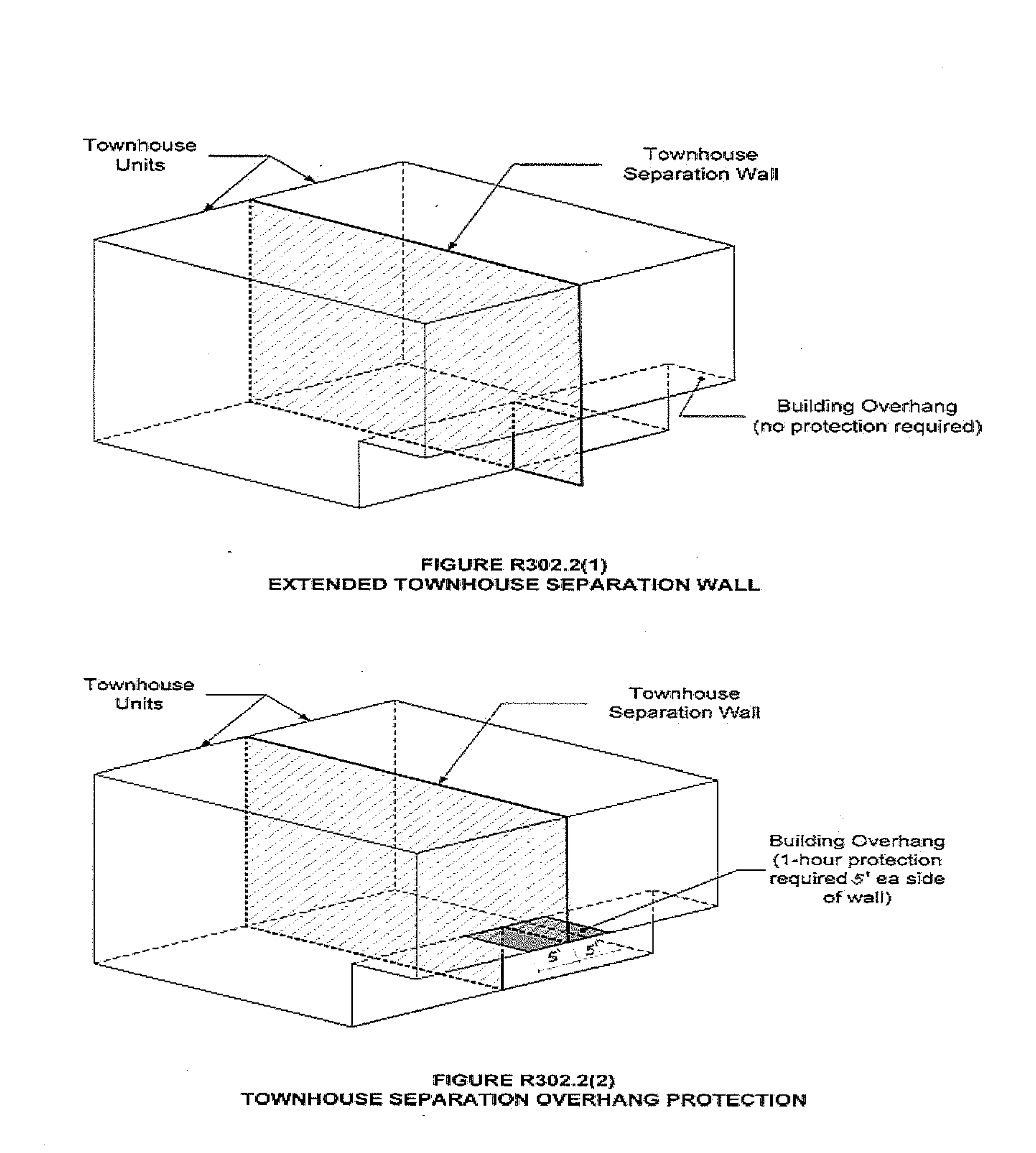
R302.2.3Continuity. The fire-resistance-rated wall or assembly separating townhouse units shall be continuous from the foundation to the underside of the roof sheathing, deck or slab. The fire-resistance rating shall extend the full length of the wall or assembly, including wall extensions through and separating attached enclosed accessory structures.
Where a story extends beyond the exterior wall of a story below:
1. The fire-resistance-rated wall or assembly shall extend to the outside edge of the upper story (see Figure R302.2(1)); or
2. The underside of the exposed floor-ceiling assembly shall be protected as required for projections in Section R302 (see Figure R302.2(2)).
R302.2.4 Parapets for townhouses. Parapets constructed in accordance with Section R302.2.5 shall be constructed for townhouses as an extension of exterior walls or common walls separating townhouse units in accordance with the following:
1. Where roof surfaces adjacent to the wall or walls are at the same elevation, the parapet shall extend not less than 30 inches (762 mm) above the roof surfaces.
2. Where roof surfaces adjacent to the wall or walls are at different elevations and the higher roof is not more than 30 inches (762 mm) above the lower roof, the parapet shall extend not less than 30 inches (762 mm) above the lower roof surface.
EXCEPTION: | A parapet is not required in the preceding two cases where the roof covering complies with a minimum Class C rating as tested in accordance with ASTM E108 or UL 790 and the roof decking or sheathing is of noncombustible materials or fire retardant-treated wood for a distance of 4 feet (1219 mm) on each side of the wall or walls, or one layer of 5/8-inch (15.9 mm) Type X gypsum board is installed directly beneath the roof decking or sheathing, supported by not less than nominal 2-inch (51 mm) ledgers attached to the sides of the roof framing members, for a distance of not less than 4 feet (1219 mm) on each side of the wall or walls and any openings or penetrations in the roof are not within 4 feet (1219 mm) of the common walls. Fire retardant-treated wood shall meet the requirements of Sections R802.1.5 and R803.2.1.2. |
3. A parapet is not required where roof surfaces adjacent to the wall or walls are at different elevations and the higher roof is more than 30 inches (762 mm) above the lower roof. The common wall construction from the lower roof to the underside of the higher roof deck shall have not less than a 1-hour fire-resistance rating. The wall shall be rated for exposure from both sides.
TABLE R302.1(1)
EXTERIOR WALLS
No Change to the Table
a | The fire-resistance rating shall be permitted to be reduced to 0 hours on the underside of the eave overhang if fireblocking is provided from the wall top plate to the underside of the roof sheathing. |
b | The fire-resistance rating shall be permitted to be reduced to 0 hours on the underside of the rake overhang where ventilation openings are not installed in the rake overhang or in walls that are common to attic areas. |
TABLE R302.1(2)
EXTERIOR WALLS - DWELLINGS WITH FIRE SPRINKLERS
No Change to the Table
a | For residential subdivisions where all dwellings are equipped throughout with an automatic sprinkler system installed in accordance with Section P2904, the fire separation distance for exterior walls not fire-resistance-rated and for fire-resistance-rated projections shall be permitted to be reduced to 0 feet, and unlimited unprotected openings and penetrations shall be permitted, where the adjoining lot provides an open setback yard that is 6 feet or more in width on the opposite side of the property line. |
b | The fire-resistance rating shall be permitted to be reduced to 0 hours on the underside of the eave overhang if fireblocking is provided from the wall top plate to the underside of the roof sheathing. |
c | The fire-resistance rating shall be permitted to be reduced to 0 hours on the underside of the rake overhang where ventilation openings are not installed in the rake overhang or in walls that are common to attic areas. |
R302.3 Two-family dwellings. Wall and floor/ceiling assemblies separating dwelling units in two-family dwellings shall be constructed in accordance with Section R302.3.1 or R302.3.3. One accessory dwelling unit constructed within an existing dwelling unit need not be considered a separated dwelling unit in a two-family dwelling where all required smoke alarms, in the accessory dwelling unit and the primary dwelling unit, are interconnected in such a manner that the actuation of one alarm will activate all alarms in both the primary dwelling unit and the accessory dwelling unit.
R302.3.1 Separation.Dwelling units in two-family dwellings shall be separated from each other by wall and floor assemblies having not less than a 1-hour fire-resistance rating where tested in accordance with ASTM E119, UL 263 or Section 703.3 of the International Building Code.
EXCEPTIONS: | 1. A fire-resistance rating of 1/2 hour shall be permitted in buildings equipped throughout with an automatic sprinkler system installed in accordance with NFPA 13D. |
| 2. Where an accessory dwelling unit is added within an existing single-family residence to create a two-family dwelling, fire rated separation between the accessory dwelling unit and the primary dwelling unit is not required when all required smoke alarms are interconnected in such a manner that the actuation of one alarm will activate all alarms in both the primary dwelling unit and the accessory dwelling unit. |
R302.3.2 Continuity. Fire-resistance-rated floor/ceiling and wall assemblies shall extend to and be tight against the exterior wall, and wall assemblies shall extend from the foundation to the underside of the roof sheathing.
EXCEPTION: | Wall assemblies need not extend through attic spaces where the ceiling is protected by not less than 5/8-inch (15.9 mm) Type X gypsum board, an attic draft stop constructed as specified in Section R302.12.1 is provided above and along the wall assembly separating the dwellings and the structural framing supporting the ceiling is protected by not less than 1/2-inch (12.7 mm) gypsum board or equivalent. |
R302.3.3 Supporting construction. Where floor/ceiling assemblies are required to be fire-resistance rated by Section R302.3, the supporting construction of such assemblies shall have an equal or greater fire-resistance rating.
((R302.4.1 Through penetrations. Through penetrations of fire-resistance-rated wall or floor assemblies shall comply with Section R302.4.1.1 or R302.4.1.2.
EXCEPTION: | Where the penetrating items are steel, ferrous or copper pipes, tubes or conduits, or fire sprinkler piping, the annular space shall be protected as follows: |
| 1. In concrete or masonry wall or floor assemblies, concrete, grout or mortar shall be permitted where installed to the full thickness of the wall or floor assembly or the thickness required to maintain the fire-resistance rating, provided that both of the following are complied with: |
| 1.1. The nominal diameter of the penetrating item is not more than 6 inches (152 mm). |
| 1.2. The area of the opening through the wall does not exceed 144 square inches (92900 mm2). |
| 2. The material used to fill the annular space shall prevent the passage of flame and hot gases sufficient to ignite cotton waste where subjected to ASTM E119 or UL 263 time temperature fire conditions under a positive pressure differential of not less than 0.01 inch of water (3 Pa) at the location of the penetration for the time period equivalent to the fire-resistance rating of the construction penetrated.)) |
R302.3.4. Openings protection between two-family dwellings. Openings in the common fire-resistance-rated wall assembly located between units of a two-family dwelling shall be equipped with not less than a 45-minute fire-rated door assembly equipped with a self-closing or automatic-closing device.
EXCEPTION: | A 20-minute fire-rated door assembly is permitted in buildings equipped throughout with an automatic sprinkler system installed in accordance with Section P2904 or 13D. |
R302.3.5 Shared accessory rooms or areas. Shared accessory rooms shall be separated by Table R302.3.5. Openings in a shared accessory room shall comply with Section R302.3.5.1. Attachment of gypsum board shall comply with Table R702.3.5. Shared accessory rooms or spaces shall not include habitable space.
R302.3.5.1 Opening protection. Openings from a shared accessory room or area directly into a room used for sleeping purposes shall not be permitted. Other openings between the shared common accessory room or area shall be equipped with solid wood doors not less than 1 3/8 inches in thickness, solid or honeycomb core steel doors not less than 1 3/8 inches thick, or 20-minute fire-rated doors, equipped with a self-closing or automatic-closing device.
TABLE R302.3.5
DWELLING-SHARED ACCESSORY ROOM SEPARATION
SEPARATION | MATERIAL |
From the dwelling units and attics. | Not less than 1/2-inch gypsum board or equivalent applied to the accessory room side wall. |
From habitable rooms above or below the shared accessory room. | Not less than 5/8-inch Type X gypsum board or equivalent. |
Structures supporting floor/ceiling and wall assemblies used for separation required by this section. | Not less than 1/2-inch gypsum board or equivalent. |
Shared accessory rooms located less than 3 feet from a dwelling unit on the same lot. | Not less than 1/2-inch gypsum board or equivalent applied to the interior side of exterior walls that are within this area. |
R302.13 Fire protection of floors. Floor assemblies that are not required elsewhere in this code to be fire-resistance rated, shall be provided with a 1/2-inch (12.7 mm) gypsum wallboard membrane, 5/8-inch (16 mm) wood structural panel membrane, or equivalent on the underside of the floor framing member. Penetrations or openings for ducts, vents, electrical outlets, lighting, devices, luminaires, wires, speakers, drainage, piping and similar openings or penetrations shall be permitted.
EXCEPTIONS: | 1. Floor assemblies located directly over a space protected by an automatic sprinkler system in accordance with Appendix U, NFPA 13D, or other approved equivalent sprinkler system. |
| 2. Floor assemblies located directly over a crawl space not intended for storage or fuel-fired appliances. |
| 3. Portions of floor assemblies shall be permitted to be unprotected when complying with the following: |
| 3.1. The aggregate area of the unprotected portions shall not exceed 80 square feet per story. |
| 3.2. Fire blocking in accordance with Section R302.11.1 is installed along the perimeter of the unprotected portion to separate the unprotected portion from the remainder of the floor assembly. |
| 4. Wood floor assemblies using dimensional lumber or structural composite lumber with a cross sectional area equal to or greater than 2-inch by 10-inch nominal dimension, or other approved floor assemblies demonstrating equivalent fire performance. |
AMENDATORY SECTION(Amending WSR 20-03-023, filed 1/6/20, effective 7/1/20)
WAC 51-51-0303Section R303—Light, ventilation and heating.
R303.1 Natural light. All habitable rooms shall have an aggregate glazing area of not less than 8 percent of the floor area of such rooms.
EXCEPTION: | The glazed areas need not be installed in rooms where artificial light is provided capable of producing an average illumination of 6 footcandles (65 lux) over the area of the room at a height of 30 inches (762 mm) above the floor level. |
R303.2 Adjoining rooms. For the purpose of determining light requirements, any room shall be considered as a portion of an adjoining room when at least one-half of the area of the common wall is open and unobstructed and provides an opening of not less than one-tenth of the floor area of the interior room but not less than 25 square feet (2.3 m2).
EXCEPTION: | Openings required for light shall be permitted to open into a sunroom with thermal isolation or a patio cover, provided there is an openable area between the adjoining room and the sunroom or a patio cover of not less than one-tenth of the floor area of the interior room but not less than 20 square feet (2 m2). |
R303.3 Bathrooms. This section is not adopted.
R303.4 Minimum ventilation performance. Dwelling units shall be equipped with local exhaust and whole house ventilation systems designed and installed as specified in Section M1507.
EXCEPTION: | Additions with less than 500 square feet of conditioned floor area are exempt from the requirements in this Code for Whole House Ventilation Systems. |
((R303.5 Opening location. Outdoor intake and exhaust openings shall be located in accordance with Sections R303.5.1 and R303.5.2.))
R303.5.1 Intake openings. Mechanical and gravity outdoor air intake openings shall be located a minimum of 10 feet (3048 mm) from any hazardous or noxious contaminant, such as vents, chimneys, plumbing vents, streets, alleys, parking lots and loading docks, except as otherwise specified in this code.
For the purpose of this section, the exhaust from dwelling unit toilet rooms, bathrooms and kitchens shall not be considered as hazardous or noxious.
EXCEPTIONS: | 1. The 10-foot (3048 mm) separation is not required where the intake opening is located 3 feet (914 mm) or greater below the contaminant source. |
| 2. Vents and chimneys serving fuel-burning appliances shall be terminated in accordance with the applicable provisions of Chapters 18 and 24. |
| 3. Clothes dryer exhaust ducts shall be terminated in accordance with Section 1502.3. |
R303.5.2 Exhaust openings. Exhaust air shall not be directed onto walkways. All exhaust ducts shall terminate outside the building. Terminal elements shall have at least the equivalent net free area of the duct work.
R303.5.2.1 Exhaust ducts. Exhaust ducts shall be equipped with back-draft dampers. All exhaust ducts in unconditioned spaces shall be insulated to a minimum of R-4.
R303.7 Interior stairway illumination. Interior stairways shall be provided with an artificial light source to illuminate the landings and treads. Stairway illumination shall receive primary power from the building wiring. The light source shall be capable of illuminating treads and landings to levels not less than 1 foot-candle (11 lux) measured at the center of treads and landings. There shall be a wall switch at each floor level to control the light source where the stairway has six or more risers.
EXCEPTION: | A switch is not required where remote, central or automatic control of lighting is provided. |
R303.8 Exterior stairway illumination. Exterior stairways shall be provided with an artificial light source located at the top landing of the stairway. Stairway illumination shall receive primary power from the building wiring. Exterior stairways providing access to a basement from the outdoor grade level shall be provided with an artificial light source located at the bottom landing of the stairway.
R303.9 Required glazed openings. Required glazed openings shall open directly onto a street or public alley, or a yard or court located on the same lot as the building.
EXCEPTIONS: | 1. Required glazed openings that face into a roofed porch where the porch abuts a street, yard or court are permitted where the longer side of the porch is not less than 65 percent unobstructed and the ceiling height is not less than 7 feet (2134 mm). |
| 2. Eave projections shall not be considered as obstructing the clear open space of a yard or court. |
| 3. Required glazed openings that face into the area under a deck, balcony, bay or floor cantilever are permitted where an unobstructed pathway of not less than 36 inches (914 mm) in height, 36 inches (914 mm) in width, and no greater than 60 inches (1524 mm) in length is provided and opens to a yard or court. The pathway shall be measured from the exterior face of the glazed opening, or if the glazed opening is in a window well, at the window well wall furthest from the exterior face of the glazed opening. |
R303.10 Required heating. When the winter design temperature in Table R301.2(1) is below 60°F (16°C), every dwelling unit shall be provided with heating facilities capable of maintaining a minimum room temperature of 68°F (20°C) at a point 3 feet (914 mm) above the floor and 2 feet (610 mm) from exterior walls in all habitable rooms at design temperature. The installation of one or more portable heaters shall not be used to achieve compliance with this section.
EXCEPTION: | Unheated recreational tents or yurts not exceeding 500 square feet provided it is not occupied as a permanent dwelling. |
R303.10.1 Definitions. For the purposes of this section only, the following definitions apply.
DESIGNATED AREAS are those areas designated by a county to be an urban growth area in chapter
36.70A RCW and those areas designated by the U.S. Environmental Protection Agency as being in nonattainment for particulate matter.
SUBSTANTIALLY REMODELED means any alteration or restoration of a building exceeding 60 percent of the appraised value of such building within a 12 month period. For the purpose of this section, the appraised value is the estimated cost to replace the building and structure in kind, based on current replacement costs.
R303.10.2 Primary heating source. Primary heating sources in all new and substantially remodeled buildings in designated areas shall not be dependent upon wood stoves.
R303.10.3 Solid fuel burning devices. No new or used solid fuel burning device shall be installed in new or existing buildings unless such device is U.S. Environmental Protection Agency certified or exempt from certification by the United States Environmental Protection Agency and conforms with RCW
70.94.011,
70.94.450,
70.94.453, and
70.94.457.
EXCEPTIONS: | 1. Wood cook stoves. |
| 2. Antique wood heaters manufactured prior to 1940. |
NEW SECTION
WAC 51-51-0309Section R309—Garages and carports.
R309.6 Electric vehicle charging.
R309.6.1 Application. The provisions of this section shall apply to the construction of new dwelling units per Section R101.2 with attached private garages or attached private carports.
EXCEPTION: | Where there is no public utility or commercial power supply. |
R309.6.2 Dedicated circuit for electric vehicle charging. A minimum of one 40-ampere dedicated 208/240-volt branch circuit shall be installed in the electrical panel for each dwelling unit.
The branch circuit shall terminate at a junction box, receptacle outlet, or electric vehicle charging equipment.
AMENDATORY SECTION(Amending WSR 20-21-041, filed 10/13/20, effective 11/13/20)
WAC 51-51-03100Section 310—Emergency escape and rescue openings.
R310.1 Emergency escape and rescue opening required. Basements, habitable attics and every sleeping room shall have not less than one operable emergency escape and rescue opening. Where basements contain one or more sleeping rooms, an emergency escape and rescue opening shall be required in each sleeping room. Emergency escape and rescue openings shall open directly into a public way, or to a yard or court providing an unobstructed path with a width of not less than 36 inches (914 mm) that opens to a public way.
EXCEPTIONS: | 1. Storm shelters and basements used only to house mechanical equipment not exceeding a total floor area of 200 square feet (18.58 m). |
| 2. Where the dwelling unit or townhouse unit is equipped with an automatic sprinkler system installed in accordance with Section P2904, sleeping rooms in basements shall not be required to have emergency escape and rescue openings provided that the basement has one of the following: |
| 2.1. One means of egress complying with Section R311 and one emergency escape and rescue opening. |
| 2.2. Two means of egress complying with Section R311. |
| 3. A yard shall not be required to open directly into a public way where the yard opens to an unobstructed path from the yard to the public way. Such path shall have a width of not less than 36 inches (914 mm). The following shall not be considered obstructions: |
| 3.1. Gates with operational constraints and opening control devices without the use of keys, tools, or special knowledge. |
| 3.2. Window wells equipped with a removable cover complying with Section R310.4.4. |
((R310.1.1 Operational constraints and opening control devices. Emergency escape and rescue openings shall be operational from the inside of the room without the use of keys, tools, or special knowledge. Window opening control devices on windows serving as a required emergency escape and rescue opening shall be not more than 70 inches (177.8 cm) above the finished floor and shall comply with ASTM F2090.))
R310.2.4 Emergency escape and rescue openings under decks ((and)), porches, and cantilevers. Emergency escape and rescue openings installed under decks ((and)), porches, and cantilevers shall be fully openable and provided with an unobstructed pathway of not less than 36 inches (914 mm) in height, 36 inches (914 mm) in width, and no greater than 60 inches (1524 mm) in length that opens to a yard or court. The pathway shall be measured from the exterior face of the glazed opening, or if the glazed opening is in a window well, at the window well wall furthest from the exterior face of the glazed opening.
R310.5 Replacement windows for emergency escape and rescue openings. This section is not adopted.
AMENDATORY SECTION(Amending WSR 20-03-023, filed 1/6/20, effective 7/1/20)
WAC 51-51-0311Section R311—Means of egress.
R311.4 Vertical egress. Egress from habitable levels including habitable attics and basements not provided with an egress door in accordance with Section R311.2 shall be by ramp in accordance with Section R311.8 or a stairway in accordance with Section R311.7.
EXCEPTION: | ((Stairs))Stairways, alternating tread devices, ship's ladders, or ladders within an individual dwelling unit or sleeping unit used for access to areas of 200 square feet (18.6 m2) or less, ((and not containing the primary bathroom or kitchen))are exempt from the requirements of Sections R311.4 and R311.7, where such devices do not provide exclusive access to a kitchen or bathroom. Such areas shall not be located more than 10 feet (3048 mm) above the finished floor of the space below. |
((R311.7.3 Vertical rise. A flight of stairs shall not have a vertical rise larger than 12 feet 7 inches (3835 mm) between floor levels or landings.))
R311.7.11 Alternating tread devices. Alternating tread devices shall not be used as an element of a means of egress. Alternating tread devices shall be permitted provided that a required means of egress stairway or ramp serves the same space at each adjoining level or where a means of egress is not required. The clear width at and below the handrails shall be not less than 20 inches (508 mm).
R311.7.12 Ship's ladders. Ship's ladders shall not be used as an element of a means of egress. Ship's ladders shall be permitted provided that a required means of egress stairway or ramp serves the same space at each adjoining level or where a means of egress is not required. The clear width at and below the handrails shall be not less than 20 inches.
NEW SECTION
WAC 51-51-0312Section R312—Guards and window fall protection.
R312.1.1 Where required.Guards shall be provided for those portions of open-sided walking surfaces, including mezzanines, lofts in accordance with Section R333, stairs, ramps, and landings, that are located more than 30 inches (762 mm) measured vertically to the floor or grade below at any point within 36 inches (914 mm) horizontally to the edge of the open side. Insect screening shall not be considered as a guard.
R312.1.2 Height. Required guards at open-sided walking surfaces, including stairs, porches, balconies or landings, shall be not less than 36 inches (914 mm) in height as measured vertically above the adjacent walking surface or the line connecting the nosings.
EXCEPTIONS: | 1. Guards on the open sides of stairs shall have a height of not less than 34 inches (864 mm) measured vertically from a line connecting the nosings. |
| 2. Where the top of the guard serves as a handrail on the open sides of stairs, the top of the guard shall be not less than 34 inches (864 mm) and not more than 38 inches (965 mm) as measured vertically from a line connecting the nosings. |
| 3. In areas with ceiling heights of 7 feet (2134 mm) or less in lofts constructed in accordance with Section R333, guards shall not be less than 36 inches (914 mm) in height or one-half of the clear height from the loft floor to the loft ceiling, whichever is less. |
AMENDATORY SECTION(Amending WSR 20-03-023, filed 1/6/20, effective 7/1/20)
WAC 51-51-0313Section R313—Automatic fire sprinkler systems.
R313.1 Townhouse automatic fire sprinkler systems. An automatic residential fire sprinkler system shall be installed in a townhouse unit.
EXCEPTIONS: | 1. An automatic residential fire sprinkler system shall not be required where additions or alterations are made to an existing townhouse unit that does not have an automatic residential fire sprinkler system installed. |
| 2. Townhouse buildings containing no more than four townhouse units. |
R313.1.1 Design and installation. Automatic residential fire sprinkler systems for a townhouse unit shall be designed and installed in accordance with Section P2904 or NFPA 13D.
R313.2 One- and two-family dwellings automatic ((fire)) sprinkler systems. This section is not adopted.
AMENDATORY SECTION(Amending WSR 20-21-041, filed 10/13/20, effective 11/13/20)
WAC 51-51-0314Section R314—Smoke alarms and heat detection.
R314.1 General. Smoke alarms, heat detectors, and heat alarms shall comply with NFPA 72 and this section.
R314.1.1 Listings. Smoke alarms shall be listed in accordance with UL 217. Heat detectors and heat alarms shall be listed for the intended application. Combination smoke and carbon monoxide alarms shall be listed in accordance with UL 217 and UL 2034.
R314.2 Where required. Smoke alarms, heat detectors, and heat alarms shall be provided in accordance with this section.
R314.2.1 New construction. Smoke alarms shall be provided in dwelling units. A heat detector or heat alarm shall be provided in new attached garages.
R314.2.2 Alterations, repairs and additions. Where alterations, repairs or additions requiring a permit occur, or where one or more sleeping rooms are added or created in existing dwellings, or where an accessory dwelling unit is created within an existing dwelling unit, each dwelling unit shall be equipped with smoke alarms as required for new dwellings.
EXCEPTIONS: | 1. Work involving the exterior surfaces of dwellings, such as the replacement of roofing or siding, the addition or replacement of windows or doors, or the addition of a porch or deck are exempt from the requirements of this section. |
| 2. Installation, alteration or repairs of plumbing, electrical or mechanical systems are exempt from the requirements of this section. |
R314.2.3 New attached garages. A heat detector or heat alarm rated for the ambient outdoor temperatures and humidity shall be installed in new garages that are attached to or located under new and existing dwellings. Heat detectors and heat alarms shall be installed in a central location and in accordance with the manufacturer's instructions.
EXCEPTION: | Heat detectors and heat alarms shall not be required in dwellings without commercial power. |
R314.3 Location. Smoke alarms shall be installed in the following locations:
1. In each sleeping room ((or sleeping loft)).
2. Outside each separate sleeping area in the immediate vicinity of the bedrooms.
3. On each additional story of the dwelling, including basements and habitable attics but not including crawl spaces and uninhabitable attics. In dwellings or dwelling units with split levels and without an intervening door between the adjacent levels, a smoke alarm installed on the upper level shall suffice for the adjacent lower level provided that the lower level is less than one full story below the upper level.
4. Smoke alarms shall be installed not less than 3 feet (914 mm) horizontally from the door or opening of a bathroom that contains a bathtub or shower unless this would prevent placement of a smoke alarm required by Section R314.3.
5. In napping areas in a family home child care.
6. In the hallway and in the room open to the hallway in dwelling units where the ceiling height of a room open to a hallway serving bedrooms exceeds that of the hallway by 24 inches (610 mm) or more.
7. Within the room to which a loft is open, in the immediate vicinity of the loft.
R314.4 Interconnection. Where more than one smoke alarm is required to be installed within an individual dwelling unit in accordance with Section R314.2, the alarm devices shall be interconnected in such a manner that the actuation of one alarm will activate all of the alarms in the individual dwelling unit. Where an accessory dwelling unit is created within an existing dwelling unit all required smoke alarms, in the accessory dwelling unit and the primary dwelling unit, shall be interconnected in such a manner that the actuation of one alarm will activate all alarms in both the primary dwelling unit and the accessory dwelling unit. Physical interconnection of smoke alarms shall not be required where listed wireless alarms are installed and all alarms sound upon activation of one alarm.
EXCEPTION: | Smoke alarms and alarms installed to satisfy Section R314.4.1 shall not be required to be interconnected to existing smoke alarms where such existing smoke alarms are not interconnected or where such new smoke alarm or alarm is not capable of being interconnected to the existing smoke alarms. |
R314.4.1 Heat detection interconnection. Heat detectors and heat alarms shall be connected to an alarm or a smoke alarm that is installed in the dwelling. Alarms and smoke alarms that are installed for this purpose shall be located in a hallway, room, or other location that will provide occupant notification.
R314.6 Power source. Smoke alarms, heat alarms, and heat detectors shall receive their primary power from the building wiring where such wiring is served from a commercial source and, where primary power is interrupted, shall receive power from a battery. Wiring shall be permanent and without a disconnecting switch other than those required for overcurrent protection.
EXCEPTIONS: | 1. Smoke alarms shall be permitted to be battery operated where installed in buildings without commercial power. |
| 2. Smoke alarms installed in accordance with Section R314.2.2 shall be permitted to be battery powered. |
AMENDATORY SECTION(Amending WSR 20-03-023, filed 1/6/20, effective 7/1/20)
WAC 51-51-0326Section R326—Habitable attic.
R326.1 General.Habitable attics shall comply with Sections R326 through R326.4.
((R326.2 Minimum dimensions. A habitable attic shall have a minimum floor area in accordance with Section R304 and a ceiling height in accordance with Section R305.
R326.3 Story above grade plane. A habitable attic shall be considered a story above grade plane.
EXCEPTION: | A habitable attic shall not be considered a story above grade plane provided that the habitable attic meets all the following requirements: |
| 1. The aggregate area of the habitable attic is not greater than one-half of the floor area of the story below. |
| 2. The habitable attic is located within a dwelling unit equipped with a fire sprinkler system in accordance with Section P2904 or NFPA 13D. |
| 3. The occupiable space is enclosed by the roof assembly above, knee walls (if applicable) on the sides and the floor-ceiling assembly below. |
| 4. The floor of the habitable attic shall not extend beyond the exterior walls of the story below. |
R326.4 Means of egress. The means of egress for habitable attics shall comply with the applicable provisions of Section R311.))
EXCEPTION: | Lofts in dwelling units and sleeping units shall be permitted to comply with Section R333, subject to the limitations in Section R333.1. |
AMENDATORY SECTION(Amending WSR 20-03-023, filed 1/6/20, effective 7/1/20)
WAC 51-51-0327((Section R327—Sleeping lofts.))Section R327—Swimming pools, spas, and hot tubs.
((R327.1 General.Sleeping lofts shall comply with Sections R327 through R327.5.
R327.2 Sleeping loft area and dimensions.Sleeping lofts shall meet the minimum area and dimension requirements of Sections R327.2.1 through R327.2.3.
R327.2.1 Area.Sleeping lofts shall have a floor area of not less than 35 square feet (3.25 m2) and less than 70 square feet (6.5 m2).
R327.2.2 Minimum horizontal dimensions.Sleeping lofts shall be not less than 5 feet (1524 mm) in any horizontal dimension.
R327.2.3 Height effect on sleeping loft area. Portions of a sleeping loft with a sloped ceiling measuring less than 3 feet (914 mm) from the finished floor to the finished ceiling shall not be considered as contributing to the minimum required area for the loft but shall contribute to the maximum allowable area.
EXCEPTION: | Under gable roofs with a minimum slope of 6 units vertical in 12 units horizontal (50 percent slope), portions of a sleeping loft with a sloped ceiling measuring less than 16 inches (406 mm) from the finished floor to the finished ceiling shall not be considered as contributing to the minimum required area for the sleeping loft but shall contribute to the maximum allowable area. |
R327.3 Sleeping loft access and egress. The access to and primary egress from sleeping lofts shall be of any type described in Sections R327.3.1 through R327.3.5 and shall meet the sleeping loft where the sleeping loft's ceiling height is not less than 3 feet (914 mm) along the entire width of the access and egress component.
R327.3.1 Stairways. Stairways accessing sleeping lofts shall comply with Sections R327.3.1.1 through R327.3.1.7.
R327.3.1.1 Headroom. The headroom above the sleeping loft access and egress shall be not less than 6 feet 2 inches (1880 mm), as measured vertically, from a sloped line connecting the tread, landing, or landing platform nosing's in the center of their width, and vertically from the landing or landing platform along the center of its width.
R327.3.1.2 Width. Stairways accessing a sleeping loft shall not be less than 17 inches (432 mm) in clear width at or above the handrail. The width below the handrail shall be not less than 20 inches (508 mm).
R327.3.1.3 Treads and risers. Risers for stairs accessing a sleeping loft shall be not less than 7 inches (178 mm) and not more than 12 inches (305 mm) in height. Tread depth and riser height shall be calculated in accordance with one of the following formulas:
1. Under gable roofs with a minimum slope of 6 units vertical in 12 units horizontal (50 percent slope), portions of a sleeping loft with a sloped ceiling measuring less than 16 inches (406 mm) from the finished floor to the finished ceiling shall not be considered as contributing to the minimum required area for the sleeping loft but shall contribute to the maximum allowable area.
2. The tread depth shall be 20 inches (508 mm) minus four-thirds of the riser height.
R327.3.1.4 Landings. Intermediate landings and landings at the bottom of stairways shall comply with Section R311.7.6, except that the depth in the direction of travel shall be not less than 24 inches (508 mm).
R327.3.1.5 Landing platforms. The top tread and riser of stairways accessing sleeping lofts shall be constructed as a landing platform where the loft ceiling height is less than 6 feet 2 inches (1880 mm) where the stairway meets the sleeping loft. The landing platform shall be not less than 18 inches (508 mm) in width and in depth measured horizontally from and perpendicular to the nosing of the landing platform. The landing platform riser height to the edge of the sleeping loft floor, shall not be greater than 18 inches (406 to 457 mm) in height.
R327.3.1.6 Handrails. Handrails shall comply with Section R311.7.8.
R327.3.1.7 Stairway guards. Guards at open sides of stairways, landings, and landing platforms shall comply with Section R312.1.
R327.3.2 Ladders. Ladders accessing sleeping lofts shall comply with Sections R326.3.2.1 and R326.3.2.2.
R327.3.2.1 Size and capacity. Ladders accessing sleeping lofts shall have a rung width of not less than 12 inches (305 mm), and 10 inch (254 mm) to 14 inch (356 mm) spacing between rungs. Ladders shall be capable of supporting a 300 pound (136 kg) load on any rung. Rung spacing shall be uniform within 3/8 inch (9.5 mm).
R327.3.2.2 Incline. Ladders shall be installed at 70 to 80 degrees from horizontal.
R327.3.3 Alternating tread devices. Alternating tread devices accessing sleeping lofts shall comply with Sections R311.7.11.1 and R311.7.11.2. The clear width at and below the handrails shall be not less than 20 inches (508 mm).
R327.3.4 Ships ladders. Ships ladders accessing sleeping lofts shall comply with Sections R311.7.12.1 and R311.7.12.2. The clear width at and below handrails shall be not less than 20 inches (508 mm).
R327.4 Sleeping loft guards.Sleeping loft guards shall be located along the open side(s) of sleeping lofts. Sleeping loft guards shall be not less than 36 inches (914 mm) in height or one-half of the clear height to the ceiling, whichever is less. Sleeping loft guards shall comply with Section R312.1.3 and Table R301.5 for their components.
R327.5 Emergency escape and rescue openings. An egress roof access window shall be installed in each sleeping loft and shall be deemed to meet the requirements of Section R310 where installed such that the bottom of the opening is not more than 44 inches (1118 mm) above the sleeping loft floor, provided the egress roof access window complies with the minimum opening area requirements of Section R310.2.1.))
R327.1 General. The design and construction of swimming pools, spas, and other aquatic recreation facilities shall comply with the 2018 International Swimming Pool and Spa Code, if the facility is one of the following:
1. For the sole use of residents and invited guests at a single-family dwelling;
2. For the sole use of residents and invited guests of a duplex owned by the residents; or
3. Operated exclusively for physical therapy or rehabilitation and under the supervision of a licensed medical practitioner.
AMENDATORY SECTION(Amending WSR 20-03-023, filed 1/6/20, effective 7/1/20)
WAC 51-51-0328((Section R328—Swimming pools, spas, and hot tubs.))Section R328—Energy storage systems.
((R328.1 General. The design and construction of swimming pools, spas, and other aquatic recreation facilities shall comply with the 2018 International Swimming Pool and Spa Code, if the facility is one of the following:
1. For the sole use of residents and invited guests at a single-family dwelling;
2. For the sole use of residents and invited guests of a duplex owned by the residents; or
3. Operated exclusively for physical therapy or rehabilitation and under the supervision of a licensed medical practitioner.))
R328.2 Equipment listings. ESS shall be listed and labeled for residential use in accordance with UL 9540.
EXCEPTIONS: | 1. Where approved, repurposed unlisted battery systems from electric vehicles are allowed to be installed outdoors or in detached sheds located not less than 5 feet (1524 mm) from exterior walls, property lines, and public ways. |
| 2. Battery systems that are an integral part of an electric vehicle are allowed provided that the installation complies with Section 625.48 of NFPA 70. |
| 3. Battery systems less than 1 kWh (3.6 megajoules). |
R328.12 Commissioning. ESS shall be commissioned as follows:
1. Verify that the system is installed in accordance with the approved plans and manufacturer's instructions and is operating properly.
2. Provide a copy of the manufacturer's installation, operation, maintenance, and decommissioning instructions provided with the listed system.
3. Provide a label on the installed system containing the contact information for the qualified maintenance and service providers.
R328.12.1 Installation prior to closing. Where the system is installed in a one- or two-family dwelling or townhouse unit that is owned by the builder and has yet to be sold, commissioning shall be conducted as outlined in Section R329.6, and the builder shall then transfer the required information in Section R329.6 to the homeowner when the property is transferred to the owner at the closing.
AMENDATORY SECTION(Amending WSR 20-03-023, filed 1/6/20, effective 7/1/20)
WAC 51-51-0329((Section R329—Energy storage systems.))Reserved.
((R329.1 General.Energy storage systems (ESS) shall comply with the provisions of this section.
R329.2 Equipment listings. ESS shall be listed and labeled for residential use in accordance with UL 9540.
EXCEPTIONS: | 1. Where approved, repurposed unlisted battery systems from electric vehicles are allowed to be installed outdoors or in detached sheds located not less than 5 feet (1524 mm) from exterior walls, property lines and public ways. |
| 2. Battery systems that are an integral part of an electric vehicle are allowed provided that the installation complies with Section 625.48 of NFPA 70. |
| 3. Battery systems less than 1 kWh (3.6 megajoules). |
R329.3 Installation. ESS shall be installed in accordance with the manufacturer's instructions and their listing, if applicable, and shall not be installed within the habitable space of a dwelling unit.
R329.4 Electrical installation. ESS shall be installed in accordance with NFPA 70. Inverters shall be listed and labeled in accordance with UL 1741 or provided as part of the UL 9540 listing. Systems connected to the utility grid shall use inverters listed for utility interaction.
R329.5 Ventilation. Indoor installations of ESS that include batteries that produce hydrogen or other flammable gases during charging shall be provided with ventilation in accordance with Section M1307.4.
R329.6 Commissioning. ESS shall be commissioned as follows:
1. Verify that the system is installed in accordance with the approved plans and manufacturer's instructions and is operating properly.
2. Provide a copy of the manufacturer's installation, operation, maintenance, and decommissioning instructions provided with the listed system.
3. Provide a label on the installed system containing the contact information for the qualified maintenance and service providers.
R329.6.1 Installation prior to closing. Where the system is installed in a one- or two-family dwelling or townhouse unit that is owned by the builder and has yet to be sold, commissioning shall be conducted as outlined in Section R329.6, and the builder shall then transfer the required information in Section R329.6 to the homeowner when the property is transferred to the owner at the closing.
R329.7 Protection from impact. ESS installed in a location subject to vehicle damage shall be protected by approved barriers.))
NEW SECTION
WAC 51-51-0333Section R333—Lofts.
R333.1 General. Where provided in dwelling units or sleeping units, lofts shall comply with this code as modified by Sections R326.1 through R326.5. Lofts constructed in compliance with this section shall be considered a portion of the story below. Such lofts shall not contribute to the number of stories as regulated by this code.
EXCEPTION: | Lofts need not comply with Section R326 where they meet any of the following conditions: |
| 1. The loft has a maximum depth of less than 3 feet (914 mm). |
| 2. The loft has a floor area of less than 35 square feet (3.3 m2). |
| 3. The loft is not provided with a permanent means of egress. |
R333.2 Loft limitations. Lofts shall comply with the following conditions:
1. The loft floor area shall be less than 70 square feet (6.5 m2).
2. The loft ceiling height shall not exceed 7 feet (2134 mm) for more than one half of the loft floor area.
The provisions of Sections R326.3 through R326.5 shall not apply to lofts that do not comply with Items 1 and 2 of this section.
R333.3 Loft ceiling height. The ceiling height below a loft shall not be less than 7 feet (2134 mm). The ceiling height above the finished floor of the loft shall not be less than 3 feet (914 mm). Portions of the loft with a sloped ceiling measuring less than 3 feet (914 mm) from the finished floor to the finished ceiling shall not contribute to the loft floor area.
R333.4 Loft area. The aggregate area of all lofts and mezzanines within a room shall comply with Section R325.3.
EXCEPTION: | The area of a single loft located within a dwelling unit or sleeping unit equipped with an automatic sprinkler system in accordance with Sections P2094 through P2904 shall not be greater than two-thirds of the area of the room in which it is located, provided that no other lofts or mezzanines are open to the room in which the loft is located. |
R333.5 Permanent egress for lofts. Where a permanent means of egress is provided for lofts, the means of egress shall comply with Section R311 as modified by Section R326.5.1.
R333.5.1 Ceiling height at loft means of egress. A minimum ceiling height of 3 feet shall be provided for the entire width of the means of egress from the loft.
NEW SECTION
WAC 51-51-0334Section R334—Stationary fuel cell power systems.
R330.1 General. Stationary fuel cell power systems in new and existing buildings and structures shall comply with Section 1206 of the International Fire Code.
AMENDATORY SECTION(Amending WSR 20-03-023, filed 1/6/20, effective 7/1/20)
WAC 51-51-0403Section R403—Footings.
R403.1.1 Minimum size. The minimum width, W, and thickness, T, for concrete footings shall be in accordance with Tables R403.1(1) through R403.1(3) and Figure R403.1(1) or R403.1.3, as applicable, but not less than 12 inches (305 mm) in width and 6 inches (152 mm) in depth. The footing width shall be based on the load-bearing value of the soil in accordance with Table R401.4.1. Footing projections, P, shall be not less than 2 inches (51 mm) and shall not exceed the thickness of the footing. Footing thickness and projection for fireplaces shall be in accordance with Section R1001. The size of footings supporting piers and columns shall be based on the tributary load and allowable soil pressure in accordance with Table R401.4.1. Footings for wood foundations shall be in accordance with the details set forth in Section R403.2, and Figures R403.1(2) and R403.1(3). Footings for precast foundation shall be in accordance with the details set forth in Section R403.4, Table R403.4, and Figures R403.4(1) and R403.4(2).
EXCEPTION: | Light-frame construction shall be permitted to have minimum footing size in accordance with Figures R403.1.1(1) through R403.1.1(4) in lieu of that determined by Table R403.1(1). |
Figure R403.1.1(1)
Alternative Minimum Footing Size for Light-Frame Construction a,b,c,d,e,f,g,h,i
20 PSF Snow Load
Notes: | a | The minimum footing size is based on the following assumptions: Material weights per Section R301.2.2.2.1 and soil density = 120 pcf. Wood framed walls = 10 foot; crawlspace stem wall = 6 inches × 36 inches; basement wall = 8 inches × 120 inches. Total load (TL) equal to the maximum of three load combinations: LC1=D+L, LC2=D+S and LC3=D=0.75(L+S), where D=dead load, L=live load, S=snow load. TL=max (LC1, LC2, LC3). |
| b | Use tributary span of floor and roof. Figure may be used to size exterior and interior footings. |
| c | Add 4 feet to tributary floor span for each wood framed wall above first level (i.e., 4' for 2-story, 8' for 3-story). |
| d | Multiply floor span by 1.25 for interior footings supporting continuous joists. |
| e | Multiply footing width by (1500 psf/capacity) for soil capacity other than 1500 psf. See Section R403.1.1 for thickness. |
| f | Dashed line may be used for interior footing size only. |
| g | Use footing size indicated on line above the span combination used. |
| h | For span combinations above the upper line, a design professional is required. |
| i | Interpolation between footing sizes is allowed. Extrapolation is not allowed. |
Figure R403.1.1(2)
Alternative Minimum Footing Size for Light-Frame Construction a,b,c,d,e,f,g,h,i
30 PSF Snow Load
Notes: | a | The minimum footing size is based on the following assumptions: Material weights per Section R301.2.2.2.1 and soil density = 120 pcf. Wood framed walls = 10 foot; crawlspace stem wall = 6 inches × 36 inches; basement wall = 8 inches × 120 inches. Total load (TL) equal to the maximum of three load combinations: LC1=D+L, LC2=D+S and LC3=D=0.75(L+S), where D=dead load, L=live load, S=snow load. TL=max (LC1, LC2, LC3). |
| b | Use tributary span of floor and roof. Figure may be used to size exterior and interior footings. |
| c | Add 4 feet to tributary floor span for each wood framed wall above first level (i.e., 4' for 2-story, 8' for 3-story). |
| d | Multiply floor span by 1.25 for interior footings supporting continuous joists. |
| e | Multiply footing width by (1500 psf/capacity) for soil capacity other than 1500 psf. See Section R403.1.1 for thickness. |
| f | Dashed line may be used for interior footing size only. |
| g | Use footing size indicated on line above the span combination used. |
| h | For span combinations above the upper line, a design professional is required. |
| i | Interpolation between footing sizes is allowed. Extrapolation is not allowed. |
Figure R403.1.1(3)
Alternative Minimum Footing Size for Light-Frame Construction a,b,c,d,e,f,g,h,i
50 PSF Snow Load
Notes: | a | The minimum footing size is based on the following assumptions: Material weights per Section R301.2.2.2.1 and soil density = 120 pcf. Wood framed walls = 10 foot; crawlspace stem wall = 6 inches × 36 inches; basement wall = 8 inches × 120 inches. Total load (TL) equal to the maximum of three load combinations: LC1=D+L, LC2=D+S and LC3=D=0.75(L+S), where D=dead load, L=live load, S=snow load. TL=max (LC1, LC2, LC3). |
| b | Use tributary span of floor and roof. Figure may be used to size exterior and interior footings. |
| c | Add 4 feet to tributary floor span for each wood framed wall above first level (i.e., 4' for 2-story, 8' for 3-story). |
| d | Multiply floor span by 1.25 for interior footings supporting continuous joists. |
| e | Multiply footing width by (1500 psf/capacity) for soil capacity other than 1500 psf. See Section R403.1.1 for thickness. |
| f | Dashed line may be used for interior footing size only. |
| g | Use footing size indicated on line above the span combination used. |
| h | For span combinations above the upper line, a design professional is required. |
| i | Interpolation between footing sizes is allowed. Extrapolation is not allowed. |
Figure R403.1.1(4)
Alternative Minimum Footing Size for Light-Frame Construction a,b,c,d,e,f,g,h,i
70 PSF Snow Load
Notes: | a | The minimum footing size is based on the following assumptions: Material weights per Section R301.2.2.2.1 and soil density = 120 pcf. Wood framed walls = 10 foot; crawlspace stem wall = 6 inches × 36 inches; basement wall = 8 inches × 120 inches. Total load (TL) equal to the maximum of three load combinations: LC1=D+L, LC2=D+S and LC3=D=0.75(L+S), where D=dead load, L=live load, S=snow load. TL=max (LC1, LC2, LC3). |
| b | Use tributary span of floor and roof. Figure may be used to size exterior and interior footings. |
| c | Add 4 feet to tributary floor span for each wood framed wall above first level (i.e., 4' for 2-story, 8' for 3-story). |
| d | Multiply floor span by 1.25 for interior footings supporting continuous joists. |
| e | Multiply footing width by (1500 psf/capacity) for soil capacity other than 1500 psf. See Section R403.1.1 for thickness. |
| f | Dashed line may be used for interior footing size only. |
| g | Use footing size indicated on line above the span combination used. |
| h | For span combinations above the upper line, a design professional is required. |
| i | Interpolation between footing sizes is allowed. Extrapolation is not allowed. |
((R403.1.6 Foundation anchorage. Wood sill plates and wood walls supported directly on continuous foundations shall be anchored to the foundation in accordance with this section.
Cold-formed steel framing shall be anchored directly to the foundation or fastened to wood sill plates in accordance with Section R505.3.1 or R603.3.1, as applicable. Wood sill plates supporting cold-formed steel framing shall be anchored to the foundation in accordance with this section.
Wood sole plates at all exterior walls on monolithic slabs, wood sole plates of braced wall panels at building interiors on monolithic slabs and all wood sill plates shall be anchored to the foundation with minimum 1/2-inch-diameter (12.7 mm) anchor bolts spaced not greater than 6 feet (1829 mm) on center or approved anchors or anchor straps spaced as required to provide equivalent anchorage to 1/2-inch-diameter (12.7 mm) anchor bolts. Bolts shall extend not less than 7 inches (178 mm) into concrete or grouted cells of concrete masonry units. The bolts shall be located in the middle third of the width of the plate. A nut and washer shall be tightened on each anchor bolt. There shall be not fewer than two bolts per plate section with one bolt located not more than 12 inches (305 mm) or less than seven bolt diameters from each end of the plate section. Interior bearing wall sole plates on monolithic slab foundation that are not part of a braced wall panel shall be positively anchored with approved fasteners. Sill plates and sole plates shall be protected against decay and termites where required by Sections R317 and R318. Anchor bolts shall be permitted to be located while concrete is still plastic and before it has set. Where anchor bolts resist placement or the consolidation of concrete around anchor bolts is impeded, the concrete shall be vibrated to ensure full contact between the anchor bolts and concrete.
EXCEPTIONS: | 1. Walls 24 inches (610 mm) total length or shorter connecting offset braced wall panels shall be anchored to the foundation with not fewer than one anchor bolt located in the center third of the plate section and shall be attached to adjacent braced wall panels at corners as shown in Item 9 of Table R602.3(1). |
| 2. Connection of walls 12 inches (305 mm) total length or shorter connecting offset braced wall panels to the foundation without anchor bolts shall be permitted. The wall shall be attached to adjacent braced wall panels at corners as shown in Item 9 of Table R602.3(1). |
R404.1.3.3.6 Form materials and form ties. Forms shall be made of wood, steel, aluminum, plastic, a composite of cement and foam insulation, a composite of cement and wood chips, or other approved material suitable for supporting and containing concrete. Forms shall be positioned and secured before placing concrete and shall provide sufficient strength to contain concrete during the concrete placement operation. Form ties shall be steel, solid plastic, foam plastic, a composite of cement and wood chips, a composite of cement and foam plastic, or other suitable material capable of resisting the forces created by fluid pressure of fresh concrete.))
AMENDATORY SECTION(Amending WSR 20-21-041, filed 10/13/20, effective 11/13/20)
WAC 51-51-0404((Section R404—Foundation and retaining walls.))Reserved.
((R404.1.3.3.6 Form materials and form ties. Forms shall be made of wood, steel, aluminum, plastic, a composite of cement and foam insulation, a composite of cement and wood chips, or other approved material suitable for supporting and containing concrete. Forms shall be positioned and secured before placing concrete and shall provide sufficient strength to contain concrete during the concrete placement operation.
Form ties shall be steel, solid plastic, foam plastic, a composite of cement and wood chips, a composite of cement and foam plastic, or other suitable material capable of resisting the forces created by fluid pressure of fresh concrete.))
AMENDATORY SECTION(Amending WSR 14-24-055, filed 11/25/14, effective 5/1/15)
WAC 51-51-0408Section R408—Under-floor space.
R408.1 Ventilation. The under-floor space between the bottom of the floor joists and the earth under any building (except space occupied by a basement) shall have ventilation openings through foundation walls or exterior walls. A ground cover of six mil (0.006 inch thick) black polyethylene or approved equal shall be laid over the ground within crawl spaces. The ground cover shall be overlapped six inches minimum at the joints and shall extend to the foundation wall.
EXCEPTION: | The ground cover may be omitted in crawl spaces if the crawl space has a concrete slab floor with a minimum thickness of two inches. |
R408.2 Openings for under-floor ventilation. The minimum net area of ventilation openings shall not be less than 1 square foot (0.0929 m2) for each 300 square feet (28 m2) of under-floor area. Required openings shall be evenly placed to provide cross ventilation of the space except one side of the building shall be permitted to have no ventilation openings. Ventilation openings shall be covered for their height and width with any of the following materials provided that the least dimension of the covering shall not exceed 1/4 inch (6.4 mm), and operational louvers are permitted:
1. Perforated sheet metal plates not less than 0.070 inch (1.8 mm) thick.
2. Expanded sheet metal plates not less than 0.047 inch (1.2 mm) thick.
3. Cast-iron grill or grating.
4. Extruded load-bearing brick vents.
5. Hardware cloth of 0.035 inch (0.89 mm) wire or heavier.
6. Corrosion-resistant wire mesh, with the least dimension being 1/8 inch (3.2 mm).
EXCEPTION: | The total area of ventilation openings shall be permitted to be reduced to 1/1,500 of the under-floor area where the ground surface is covered with an approved Class I vapor retarder material and the required openings are placed to provide cross ventilation of the space. The installation of operable louvers shall not be prohibited. If the installed ventilation is less than 1/300, or if operable louvers are installed, a radon vent shall be installed to originate from a point between the ground cover and soil. The radon vent shall be installed in accordance with the requirements of Appendix F (Radon) of this code. |
R408.3 Unvented crawl space. Ventilation openings in under-floor spaces specified in Sections R408.1 and R408.2 shall not be required where:
1. Exposed earth is covered with a continuous Class I vapor retarder. Joints of the vapor retarder shall overlap by 6 inches (152 mm) and shall be sealed or taped. The edges of the vapor retarder shall extend at least 6 inches (152 mm) up the stem wall and shall be attached and sealed to the stem wall; and a radon system shall be installed that meets the requirements of Appendix F (Radon) of this code.
2. Continuously operated mechanical exhaust ventilation is provided at a rate equal to 1 cubic foot per minute (0.47 L/s) for each 50 square feet (4.7 m2) of crawlspace floor area. Exhaust ventilation shall terminate to the exterior.
EXCEPTION: | Plenum in existing structures complying with Section M1601.5, if under-floor space is used as a plenum. |
R408.8 Under-floor vapor retarder. This section is not adopted.
AMENDATORY SECTION(Amending WSR 21-16-006, filed 7/22/21, effective 8/22/21)
WAC 51-51-0507Section R507—Decks.
((R507.1 Decks. Wood-framed decks shall be in accordance with this section. Decks shall be designed for the live load required in Section R301.5 or the ground snow load indicated in Table R301.2(1), whichever is greater. For decks using materials and conditions not prescribed in this section, refer to Section R301.))
TABLE R507.3.1
MINIMUM FOOTING SIZE FOR DECKS
LIVE OR GROUND SNOW LOAD ((b)) (psf) | TRIBUTARY AREAc (sq.ft.) | ((SOIL BEARING CAPACITY))LOAD-BEARING VALUE OF SOILSacd |
1500 psf | 2000 psf | ≥ 3000 psf |
Side of a square footing (inches) | Diameter of a round footing (inches) | Thicknessf (inches) | Side of a square footing (inches) | Diameter of a round footing (inches) | Thicknessf (inches) | Side of a square footing (inches) | Diameter of a round footing (inches) | Thicknessf (inches) |
60 Live or 70 Ground Snow Load | 5 | 7 | 8 | 6 | 7 | 8 | 6 | 7 | 8 | 6 |
20 | 12 | 14 | 6 | 11 | 13 | 6 | 9 | 10 | 6 |
40 | 18 | 20 | 6 | 15 | 17 | 6 | 12 | 14 | 6 |
60 | 21 | 24 | 8 | 19 | 21 | 6 | 15 | 17 | 6 |
80 | 25 | 28 | 9 | 21 | 24 | 8 | 18 | 20 | 6 |
100 | 28 | 31 | 11 | 24 | 27 | 9 | 20 | 22 | 7 |
120 | 30 | 34 | 12 | 26 | 30 | 10 | 21 | 24 | 8 |
140 | 33 | 37 | 13 | 28 | 32 | 11 | 23 | 26 | 9 |
160 | 35 | 40 | 15 | 30 | 34 | 12 | 25 | 28 | 9 |
For SI: 1 inch = 25.4 mm, 1 square foot = 0.0929 m2, 1 pound per square foot = 0.0479 kPa. |
a. | Interpolation permitted, extrapolation not permitted. |
b. | Reserved. |
c. | Footing dimensions shall allow complete bearing of the post. |
d. | If the support is a brick or CMU pier, the footing shall have a minimum 2-inch projection on all sides. |
e. | Area, in square feet, of deck surface supported by post and footings. |
f. | Minimum thickness shall only apply to plain concrete footings, |
R507.4 Deck posts. For single-level decks, wood post size shall be in accordance with Table R507.4.
TABLE R507.4
DECK POST HEIGHT
LOADSb (psf) | POST SPECIESc | POST SIZEd | MAXIMUM DECK POST HEIGHTa (feet-inches) |
Tributary Areag,h (sq. ft.) |
20 | 40 | 60 | 80 | 100 | 120 | 140 | 160 |
60 Live Load, ≤60 Ground Snow Load | Douglas Fire, Hem-fire, SPFe | 4 x 4 | 14-0 | 10-10 | 8-7 | 7-0 | 5-8 | 4-1 | NP | NP |
4 x 6 | 14-0 | 13-10 | 11-1 | 9-5 | 8-2 | 7-3 | 6-4 | 5-4 |
6 x 6 | 14-0 | 14-0 | 14-0 | 14-0 | 14-0 | 13-3 | 10-9 | 6-11 |
8 x 8 | 14-0 | 14-0 | 14-0 | 14-0 | 14-0 | 14-0 | 14-0 | 14-0 |
Redwoodf, Western Cedarsf, Ponderosa Pinef, Red Pinef | 4 x 4 | 14-0 | 10-3 | 7-0 | NP | NP | NP | NP | NP |
4 x 6 | 14-0 | 13-6 | 10-6 | 8-4 | 5-10 | NP | NP | NP |
6 x 6 | 14-0 | 14-0 | 14-0 | 14-0 | 11-11 | NP | NP | NP |
8 x 8 | 14-0 | 14-0 | 14-0 | 14-0 | 14-0 | 14-0 | 14-0 | 14-0 |
70 Ground Snow Load | Douglas Fire, Hem-fire, SPFe | 4 x 4 | 14-0 | 10-1 | 7-11 | 6-6 | 5-3 | 3-7 | NP | NP |
4 x 6 | 14-0 | 12-10 | 10-3 | 8-9 | 7-7 | 6-8 | 5-10 | 4-11 |
6 x 6 | 14-0 | 14-0 | 14-0 | 14-0 | 14-0 | 12-2 | 9-9 | 5-9 |
8 x 8 | 14-0 | 14-0 | 14-0 | 14-0 | 14-0 | 14-0 | 14-0 | 14-0 |
Redwoodf, Western Cedarsf, Ponderosa Pinef, Red Pinef | 4 x 4 | 14-0 | 9-5 | 6-5 | NP | NP | NP | NP | NP |
4 x 6 | 14-0 | 12-6 | 9-8 | 7-7 | 5-3 | NP | NP | NP |
6 x 6 | 14-0 | 14-0 | 14-0 | 14-0 | 10-8 | NP | NP | NP |
8 x 8 | 14-0 | 14-0 | 14-0 | 14-0 | 14-0 | 14-0 | 14-0 | 14-0 |
For SI: 1 inch = 25.4 mm, 1 square foot = 0.0929 m2, 1 pound per square foot = 0.0479 kPa, NP = Not permitted. |
a. | Measured from the underside of the beam to top of footing or pier. |
b. | 10 psf dead load. Snow load not assumed to be concurrent with live load. |
c. | No. 2 grade, wet service factor included. |
d. | Notched deck posts shall be sized to accommodate beam size per in accordance with Section R507.5.2. |
e. | Includes incising factor. |
f. | Incising factor not included. |
g. | Area, in square feet, of deck surface supported by post and footing. |
h. | Interpolation permitted. Extrapolation not permitted. |
R507.5 Deck beams. Maximum allowable spans for wood deck beams, as shown in Figure R507.5, shall be in accordance with Table R507.5. Beam plies shall be fastened with two rows of 10d (3-inch × 0.128-inch) nails minimum at 16 inches (406 mm) on center along each edge. Beams shall be permitted to cantilever at each end up to one-fourth of the allowable beam span. Deck beams of other materials shall be permitted where designed in accordance with accepted engineering practices.
Tables R507.5(1) through R507.5(4) are not adopted.
TABLE R507.5
MAXIMUM DECK BEAM SPAN - 60 PSF LIVE LOAD or
70 PSF GROUND SNOW LOADc
BEAM SPECIESd | BEAM SIZEe | EFFECTIVE DECK JOIST SPAN LENGTHa,i (feet) |
6 | 8 | 10 | 12 | 14 | 16 | 18 |
| MAXIMUM DECK BEAM SPAN LENGTHa,b,f (feet-inches) |
Douglas fir-larchg, Hem-firg, Spruce-pine-firg | 1-2×6 | 3-5 | 2-10 | 2-5 | 2-2 | 2-0 | 1-10 | 1-9 |
1-2×8 | 4-7 | 3-8 | 3-2 | 2-10 | 2-7 | 2-5 | 2-4 |
1-2×10 | 5-8 | 4-9 | 4-1 | 3-8 | 3-4 | 3-1 | 2-11 |
1-2×12 | 6-7 | 5-8 | 5-0 | 4-6 | 4-1 | 3-10 | 3-7 |
2-2×6 | 5-2 | 4-6 | 4-0 | 3-5 | 3-1 | 2-10 | 2-7 |
2-2×8 | 6-11 | 6-0 | 5-3 | 4-7 | 4-1 | 3-8 | 3-5 |
2-2×10 | 8-5 | 7-4 | 6-6 | 5-10 | 5-2 | 4-9 | 4-5 |
2-2×12 | 9-10 | 8-6 | 7-7 | 6-11 | 6-4 | 5-9 | 5-4 |
3-2×6 | 6-6 | 5-7 | 5-0 | 4-7 | 4-2 | 3-9 | 3-5 |
3-2×8 | 8-8 | 7-6 | 6-8 | 6-1 | 5-6 | 5-0 | 4-7 |
3-2×10 | 10-7 | 9-2 | 8-2 | 7-6 | 6-11 | 6-4 | 5-10 |
3-2×12 | 12-4 | 10-8 | 9-7 | 8-9 | 8-1 | 7-7 | 7-1 |
Redwoodh, Western Cedarsh, Ponderosa Pineh, Red Pineh | 1-2×6 | 3-6 | 2-11 | 2-6 | 2-3 | 2-0 | 1-11 | 1-9 |
1-2×8 | 4-6 | 3-10 | 3-3 | 2-11 | 2-8 | 2-6 | 2-4 |
1-2×10 | 5-6 | 4-9 | 4-2 | 3-9 | 3-5 | 3-2 | 3-0 |
1-2×12 | 6-4 | 5-6 | 4-11 | 4-6 | 4-2 | 3-11 | 3-8 |
2-2×6 | 5-3 | 4-7 | 4-1 | 3-6 | 3-2 | 2-11 | 2-8 |
2-2×8 | 6-8 | 5-9 | 5-2 | 4-8 | 4-2 | 3-10 | 3-6 |
2-2×10 | 8-2 | 7-1 | 6-4 | 5-9 | 5-4 | 4-10 | 4-6 |
2-2×12 | 9-5 | 8-2 | 7-4 | 6-8 | 6-2 | 5-9 | 5-5 |
3-2×6 | 6-4 | 5-8 | 5-1 | 4-8 | 4-3 | 3-10 | 3-6 |
3-2×8 | 8-4 | 7-3 | 6-5 | 5-11 | 5-5 | 5-1 | 4-8 |
3-2×10 | 10-2 | 8-10 | 7-11 | 7-2 | 6-8 | 6-3 | 5-11 |
3-2×12 | 11-10 | 10-3 | 9-2 | 8-4 | 7-9 | 7-3 | 6-10 |
For SI: 1 inch = 25.4 mm, 1 foot = 304.8 mm, 1 pound per square foot = 0.0479 kPa, 1 pound = 0.454 kg. |
a. | Interpolation allowed. Extrapolation is not allowed. |
b. | Beams supporting a single span of joists with or without cantilever. |
c. | Dead load = 10 psf, L/Δ = 360 at mainspan, L/Δ = 180 at cantilever. Snow load not assumed to be concurrent with live load. |
d. | No. 2 grade, wet service factor included. |
e. | Beam depth shall be equal to or greater than the depth of intersecting joist for a flush beam connection. |
f. | Beam cantilevers are limited to the adjacent beam's span divided by 4. |
g. | Includes incising factor. |
h. | Incising factor not included. |
i. | Deck joist span as shown in Figure R507.5. |
j. | For calculation of effective joist span, the actual joist span length shall be multiplied by the joist span factor in accordance with Table R507.5(5). |
R507.6 Deck joists. Maximum allowable spans for wood deck joists, as shown in Figure R507.6, shall be in accordance with Table R507.6. The maximum joist spacing shall be limited by the decking materials in accordance with Table R507.7.
TABLE R507.6
MAXIMUM DECK JOIST SPANS
LOADa (psf) | JOIST SPECIESb | JOIST SIZE | ALLOWABLE JOIST SPANb,c (feet-inches) | MAXIMUM CANTILEVERf,g (feet-inches) |
Joist Spacing (inches) | Adjacent Joist Back Spang (feet) |
12 | 16 | 24 | 4 | 6 | 8 | 10 | 12 | 14 | 16 | 18 |
60 Live Load or 70 Ground Snow Load | Douglas fir-larche, Hem-fire, Spruce-pine-fire | 2×6 | 7-11 | 7-1 | 5-9 | 1-0 | 1-6 | NP | NP | NP | NP | NP | NP |
2×8 | 10-5 | 9-5 | 7-8 | 1-0 | 1-6 | 2-0 | 2-1 | NP | NP | NP | NP |
2×10 | 13-3 | 11-6 | 9-5 | 1-0 | 1-6 | 2-0 | 2-6 | 2-8 | NP | NP | NP |
2×12 | 15-5 | 13-4 | 10-11 | 1-0 | 1-6 | 2-0 | 2-6 | 3-0 | 3-3 | NP | NP |
Redwoodf, Western Cedarsf, Ponderosa Pinef, Red Pinef | 2×6 | 7-4 | 6-8 | 5-10 | 1-0 | 1-4 | NP | NP | NP | NP | NP | NP |
2×8 | 9-8 | 8-10 | 7-4 | 1-0 | 1-6 | 1-11 | NP | NP | NP | NP | NP |
2×10 | 12-4 | 11-0 | 9-0 | 1-0 | 1-6 | 2-0 | 2-6 | 2-6 | NP | NP | NP |
2×12 | 14-9 | 12-9 | 10-5 | 1-0 | 1-6 | 2-0 | 2-6 | 3-0 | 3-0 | NP | NP |
For SI: 1 inch = 25.4 mm, 1 foot = 304.8 mm, 1 pound per square foot = 0.0479 kPa, 1 pound = 0.454 kg, NP = Not permitted. |
a. | Dead load = 10 psf dead load. Snow load not assumed to be concurrent with live load. |
b. | No. 2 grade, wet service factor included. |
c. | L/Δ = 360 at main span. |
d. | L/Δ = 180 at cantilever with 220-pound point load applied to end. |
e. | Includes incising factor. |
f. | Incising factor not included. |
g. | Interpolation permitted. Extrapolation not permitted. |
R507.9.1.2 Band joist details. Band joists supporting a ledger shall be a minimum 2-inch-nominal (51 mm), solid-sawn, spruce-pine-fir or better lumber or minimum 1-inch (25 mm) nominal engineered wood rim boards in accordance with Section R502.1.7. Band joists shall bear fully on the primary structure capable of supporting all required loads.
TABLE R507.9.1.3(1)
DECK LEDGER CONNECTION TO BAND JOIST
LOADc (psf) | JOIST SPANa (feet) | On-CENTER SPACING OF FASTENERSb (inches) |
1/2-inch diameter lag screw with 1/2-inch maximum sheathingd,e | 1/2-inch diameter bolt with 1/2-inch maximum sheathinge | 1/2-inch diameter bolt with 1-inch maximum sheathingf |
60 Live Load or 70 Ground Snow Load | 6 | 22 | 36 | 35 |
8 | 16 | 31 | 26 |
10 | 13 | 25 | 21 |
12 | 11 | 20 | 17 |
14 | 9 | 17 | 15 |
16 | 8 | 15 | 13 |
18 | 7 | 13 | 11 |
For SI: 1 inch = 25.4 mm, 1 foot = 304.8 mm, 1 pound per square foot = 0.0479 kPa. |
a. | Interpolation permitted. Extrapolation is not permitted. |
b. | Ledgers shall be flashed in accordance with Section R703.4 to prevent water from contacting the house band joist. |
c. | Dead load = 10 psf. Snow load shall not be assumed to act concurrently with live load. |
d. | The tip of the lag screw shall fully extend beyond the inside face of the band joist. |
e. | Sheathing shall be wood structural panel or solid sawn lumber. |
f. | Sheathing shall be permitted to be wood structural panel, gypsum board, fiberboard, lumber or foam sheathing. Up to 1/2-inch thickness of stacked washers shall be permitted to substitute for up to 1/2 inch of allowable sheathing thickness where combined with wood structural panel or lumber sheathing. |
R507.9.2 Deck lateral load connections. Lateral loads shall be transferred to the ground or to a structure capable of transmitting them to the ground. Where the lateral load connection is provided in accordance with Figure R507.9.2(1), hold-down tension devices shall be installed in not less than two locations per deck, within 24 inches of each end of the deck. Each device shall have an allowable stress design capacity of not less than 1500 pounds (6672 N). Where the lateral load connections are provided in accordance with Figure R507.9.2(2), the hold-down tension devices shall be installed in not less than four locations per deck, and each device shall have an allowable stress design capacity of not less than 750 pounds (3336 N).
EXCEPTION: | Decks not more than 30 inches above grade at any point may be unattached. |
TABLE R507.9.1
PLACEMENT OF LAG SCREWS AND BOLTS IN DECK LEDGERS AND BAND JOISTS
MINIMUM END AND EDGE DISTANCES AND SPACING BETWEEN ROWS |
| TOP EDGE | BOTTOM EDGE | ENDS | ROW SPACING |
Ledgera | 2 inchesd | 3/4 inch | 2 inchesb | 1 5/8 inchesb |
Band joistc | 3/4 inch | 2 inchese | 2 inchesb | 1 5/8 inchesb |
For SI: | 1 inch = 25.4 mm. |
a | Lag screws or bolts shall be staggered from the top to the bottom along the horizontal run of the deck ledger in accordance with Figure R507.2.1(1). |
b | Maximum 5 inches. |
c | For engineered rim joists, the manufacturer's recommendations shall govern. |
d | The minimum distance from bottom row of lag screws to the top edge of the ledger shall be in accordance with Figure R507.2.1(1). |
e | The 2 inches may be reduced to 3/4 inch when the band joist is directly supported by a mudsill, a header or by double top wall plates. |
TABLE R507.9.3(1)
DECK LEGER CONNECTION TO BAND JOIST
LOADc (psf) | JOIST SPANa (feet) | 1/2-inch diameter leg screw with 1/2-inch maximum sheathingd,e | 1/2-inch diameter bolt with 1/2-inch maximum sheathinge | 1/2-inch diameter bolt with 1-inch maximum sheathingf |
ON-CENTER SPACING OF FASTENERSb (inches) |
60 Ground Snow Load | 6 | 25 | 36 | 36 |
8 | 18 | 35 | 30 |
10 | 15 | 28 | 24 |
12 | 12 | 23 | 20 |
14 | 10 | 20 | 17 |
16 | 9 | 17 | 15 |
18 | 8 | 15 | 13 |
70 Ground Snow Load | 6 | 22 | 36 | 35 |
8 | 16 | 31 | 26 |
10 | 13 | 25 | 21 |
12 | 11 | 20 | 17 |
14 | 9 | 17 | 15 |
16 | 8 | 15 | 13 |
18 | 7 | 13 | 11 |
For SI: 1 inch = 25.4 mm, 1 foot = 304.8 mm, 1 pound per square foot = 0.0479 kPa. |
a. | Interpolation permitted. Extrapolation not permitted. |
b. | Legers shall be flashed in accordance with Section R703.4 to prevent water from contacting the house band joist. |
c. | Dead Load = 10 psf. Snow load shall not be assumed to act concurrently with live load. |
d. | The tip of the lag screw shall fully extend beyond the inside face of the band joist. |
e. | Sheathing shall be wood structural panel or solid sawn lumber. |
f. | Sheathing shall be permitted to be wood structural panel, gypsum board, fiberboard, lumber or foam sheathing. Up to 1/2 inch thickness of stacked washers shall be permitted to substitute for up to 1/2 inch of allowable sheathing thickness where combined with wood structural panel or lumber sheathing. |
AMENDATORY SECTION(Amending WSR 20-03-023, filed 1/6/20, effective 7/1/20)
WAC 51-51-0608((Section 608—Exterior concrete wall construction.))Reserved.
((R608.1 General. Exterior concrete walls shall be designed and constructed in accordance with the provisions of this section or in accordance with the provisions of PCA 100, ACI 318, or ACI 332. Where PCA 100, ACI 318, or ACI 332, or the provisions of this section are used to design concrete walls, project drawings, typical details and specifications are not required to bear the seal of the architect or engineer responsible for design, unless otherwise required by the state law of the jurisdiction having authority.
R608.5.1 Concrete and materials for concrete. Materials used in concrete, and the concrete itself, shall conform to requirements of this section, PCA 100, ACI 318, or ACI 332.))
AMENDATORY SECTION(Amending WSR 20-21-041, filed 10/13/20, effective 11/13/20)
WAC 51-51-0703Section R703—Exterior covering.
R703.1.1 Water resistance. The exterior wall envelope shall be designed and constructed in a manner that prevents the accumulation of water within the wall assembly by providing a water-resistant barrier behind the exterior veneer as required by Section R703.2 and a means of draining water that enters the assembly to the exterior. Protection against condensation in the exterior wall assembly shall be provided in accordance with Section R702.7 of this code.
EXCEPTIONS: | 1. A weather-resistant exterior wall envelope shall not be required over concrete or masonry walls designed in accordance with Chapter 6 and flashed according to Section R703.4 or R703.8. |
| 2. Compliance with the requirements for a means of drainage, and the requirements of Sections R703.2 and R703.4, shall not be required for an exterior wall envelope that has been demonstrated to resist wind-driven rain through testing of the exterior wall envelope, including joints, penetrations and intersections with dissimilar materials, in accordance with ASTM E 331 under the following conditions: |
| 2.1. Exterior wall envelope test assemblies shall include at least one opening, one control joint, one wall/eave interface and one wall sill. All tested openings and penetrations shall be representative of the intended end-use configuration. |
| 2.2. Exterior wall envelope test assemblies shall be at least 4 feet (1219 mm) by 8 feet (2438 mm) in size. |
| 2.3. Exterior wall assemblies shall be tested at a minimum differential pressure of 6.24 pounds per square foot (299Pa). |
| 2.4. Exterior wall envelope assemblies shall be subjected to a minimum test exposure duration of 2 hours. |
| The exterior wall envelope design shall be considered to resist wind-driven rain where the results of testing indicate that water did not penetrate control joints in the exterior wall envelope; joints at the perimeter of opening penetration; or intersections of terminations with dissimilar materials. |
| 3. The requirement for a means of drainage shall not be construed to mean an air space cavity under the exterior cladding for an exterior wall clad with panel or lapped siding made of plywood, engineered wood, hardboard, or fiber cement. A water-resistive barrier as required by Section R703.2 will be required on exterior walls. |
((R703.2 Water-resistive barrier. Not fewer than one layer of water-resistive barrier shall be applied over studs or sheathing with flashing as indicated in Section R703.4, in such a manner as to provide a continuous water resistive barrier behind the exterior wall veneer. Water-resistive barrier materials shall comply with one of the following:
1. No. 15 felt complying with ASTM D226, Type 1.
2. ASTM E2556, Type 1 or 2.
3. ASTM E331 in accordance with Section R703.1.1; or
4. Other approved materials in accordance with the manufacturer's installation instructions.
R703.4 Flashing. Approved corrosion-resistant flashing shall be applied shingle-fashion in a manner to prevent entry of water into the wall cavity or penetration of water to the building structure framing components. Self-adhered membranes used as flashing shall comply with AAMA 711. Fluid-applied membranes used as flashing in exterior walls shall comply with AAMA 714. The flashing shall extend to the surface of the exterior wall finish. Approved corrosion-resistant flashing shall be installed at all of the following locations:
1. Exterior window and door openings. Flashing at exterior window and door openings shall extend to the surface of the exterior wall finish or to the water resistive barrier complying with Section 703.2 for subsequent drainage. Mechanically attached flexible flashings shall comply with AAMA 712.
2. At the intersection of chimneys or other masonry construction with frame or stucco walls, with projecting lips on both sides under stucco copings.
3. Under and at the ends of masonry, wood or metal copings and sills.
4. Continuously above all projecting wood trim.
5. Where exterior porches, decks or stairs attach to a wall or floor assembly of wood-frame construction.
6. At wall and roof intersections.
7. At built-in gutters.))
R703.10.2 Lap siding. Fiber-cement lap siding having a maximum width of 12 inches (305 mm) shall comply with the requirements of ASTM C 1186, Type A, minimum Grade II or ISO 8336, Category A, minimum Class 2. Lap siding shall be lapped a minimum of 1 1/4 inches (32 mm) and lap siding shall be installed in accordance with the manufacturer's installation instructions or shall be designed to comply with Section R703.1. Lap siding courses shall be installed with the fastener heads exposed or concealed, in accordance with Table R703.3(1) or approved manufacturer's instructions.
AMENDATORY SECTION(Amending WSR 20-21-041, filed 10/13/20, effective 11/13/20)
WAC 51-51-1503Section M1503—Domestic cooking exhaust equipment.
M1503.2.1 Open-top broiler exhaust. Domestic open-top broiler units shall be provided with a metal exhaust hood, having a minimum thickness of 0.0157 inch (0.3950 mm) (No. 28 gage). Such hoods shall be installed with a clearance of not less than 1/4 inch (6.4 mm) between the hood and the underside of combustible material or cabinets. A clearance of not less than 24 inches (610 mm) shall be maintained between the cooking surface and the combustible material or cabinets. The hood width shall not be less than the width of the broiler unit and shall extend over the entire unit.
EXCEPTIONS: | 1. Broiler units that incorporate an integral exhaust system, and that are listed and labeled for use without an exhaust hood, shall not be required to have an exhaust hood. |
| 2. Broiler units permanently installed outside the building envelope and having the cooking surface at least 5 feet below a 1-hour fire resistance rated ceiling shall not be required to have an exhaust hood. |
M1503.3 Exhaust discharge. Domestic cooking exhaust equipment shall discharge to the outdoors through a duct. The duct shall have a smooth interior surface, shall be airtight, shall be equipped with a backdraft damper and shall be independent of all other exhaust systems. Ducts serving domestic cooking exhaust equipment shall not terminate in an attic or crawl space or areas inside the building.
EXCEPTION: | Where installed in accordance with the manufacturer's instructions, and where continuous local exhaust is provided in an enclosed kitchen in accordance with Table M1505.4.4(1), listed and labeled ductless range hoods shall not be required to discharge to the outdoors. |
M1503.5 Kitchen exhaust rates. Where domestic kitchen cooking appliances are provided with exhaust equipment, the fans shall be sized in accordance with Section M1505.4.4.
AMENDATORY SECTION(Amending WSR 20-12-027, filed 5/27/20, effective 7/1/20)
WAC 51-51-1505Section M1505—Mechanical ventilation.
M1505.1 General. Where local exhaust or whole-house mechanical ventilation is provided, the ventilation system shall be designed in accordance with this section.
EXCEPTION: | Alternate balanced whole-house ventilation systems and local exhaust systems designed and commissioned in accordance with ASHRAE 62.2 are permitted. |
M1505.4 Whole-house mechanical ventilation system. Each dwelling unit shall be equipped with a ventilation system. The whole-house mechanical ventilation systems shall be designed in accordance with Sections M1505.4.1 through M1505.4.4.
M1505.4.1 System design. The whole house ventilation system shall consist of one or more supply fans, one or more exhaust fans, or an ERV/HRV with integral fans, associated ducts and controls. Whole-house mechanical ventilation system with supply and exhaust fans per Sections M1505.4.1.2, M1505.4.1.3, M1505.4.1.4, and M1505.4.1.5. Local exhaust fans are permitted to serve as part of the whole house ventilation system when provided with the proper controls per Section M1505.4.2. The systems shall be designed and installed to exhaust and/or supply the minimum outdoor airflow rates per Section M1505.4.3 as modified by whole house ventilation system coefficients in Section M1505.4.3.1 where applicable. The whole house ventilation system shall operate continuously at the minimum ventilation rate determined per Section M1505.4.2 unless configured with intermittent off controls per Section M1505.4.3.2.
M1505.4.1.1 Whole house system component requirements. Whole house ventilation supply and exhaust fans specified in this section shall have a minimum efficacy as prescribed in the Washington State Energy Code. Design and installation of the system or equipment shall be carried out in accordance with manufacturers' installation instructions. Whole house ventilation fans shall be rated for sound at no less than the minimum airflow rate required by Section M1505.4.3.1. Ventilation fans shall be rated for sound at a maximum of 1.0 sone. This sound rating shall be at a minimum of 0.1 in. w.c. (25 Pa) static pressure in accordance with HVI procedures specified in Sections M1505.4.1.2 and M1505.4.1.3.
EXCEPTION: | HVAC air handlers, ERV/HRV units, and remote mounted fans need not meet the sound requirements. To be considered for this exception, a remote mounted fan must be mounted outside the habitable spaces, bathrooms, toilets, and hallways, and there must be at least 4 ft (1 m) of ductwork between the fan and the intake grille. |
The whole house supply fan shall provide ducted outdoor ventilation air to each habitable space within the residential unit.
EXCEPTION: | Interior joining spaces provided with a 30 cfm whole house transfer fan or a permanent opening with an area of not less than 8 percent of the floor area of the interior adjoining space but not less than 25 square feet do not require ducted outdoor ventilation air to be supplied directly to the space. Whole house transfer fans shall meet the sone rating of Section M1505.4.1.1 and shall have whole house ventilation controls that comply with Section M1505.4.2. |
M1505.4.1.2 Exhaust fans. Exhaust fans required shall be ducted directly to the outside. Exhaust air outlets shall be designed to limit the pressure difference to the outside and equipped with backdraft dampers or motorized dampers in accordance with the Washington State Energy Code. Exhaust fans shall be tested and rated in accordance with the airflow and sound rating procedures of the Home Ventilating Institute (HVI 915, HVI Loudness Testing and Rating Procedure, HVI 916, HVI Airflow Test Procedure, and HVI 920, HVI Product Performance Certification Procedure, as applicable). Exhaust fans required in this section may be used to provide local ventilation. Bathroom exhaust fans that are designed for intermittent exhaust airflow rates higher than the continuous exhaust airflow rates in Table M1505.4.3(3) shall be provided with occupancy sensors or humidity sensors to automatically override the fan to the high speed airflow rate. The exhaust fans shall be tested and the testing results shall be submitted and posted in accordance with Section M1505.4.1.6.
M1505.4.1.3 Supply fans. Supply fans used in meeting the requirements of this section shall supply outdoor air from intake openings in accordance with IMC Sections 401.4 and 401.5. When designed for intermittent off operation, supply systems shall be equipped with motorized dampers in accordance with the Washington State Energy Code. Supply fans shall be tested and rated in accordance with the airflow and sound rating procedures of the Home Ventilating Institute (HVI 915, HVI Loudness Testing and Rating Procedure, HVI 916, HVI Airflow Test Procedure, and HVI 920, HVI Product Performance Certification Procedure, as applicable). Where outdoor air is provided by supply fan systems the outdoor air shall be filtered. The filter shall be accessible for regular maintenance and replacement. The filter shall have a Minimum Efficiency Rating Value (MERV) of at least 8.
M1505.4.1.4 Balanced whole house ventilation system. A balanced whole house ventilation system shall include both supply and exhaust fans. The supply and exhaust fans shall have airflow that is within 10 percent of each other. The tested and balanced total mechanical exhaust airflow rate is within 10 percent or 5 cfm, whichever is greater, of the total mechanical supply airflow rate. The flow rate test results shall be submitted and posted in accordance with Section M1505.4.1.7. The exhaust fan shall meet the requirements of Section M1505.4.1.2. The supply fan shall meet the requirements of Section M1505.4.1.3. Balanced ventilation systems with both supply and exhaust fans in a packaged product, such as an ERV/HRV shall meet the requirements of HVI 920, as applicable. ((Intermittent dryer exhaust, intermittent range hood exhaust, and intermittent toilet room exhaust airflow rates above the residential dwelling or sleeping unit minimum ventilation rate))Local exhaust systems that are not a component of the whole-house mechanical ventilation system are exempt from the balanced airflow calculation.
M1505.4.1.5 Furnace integrated supply. Systems using space heating and/or cooling air handler fans for outdoor air supply distribution are not permitted.
EXCEPTION: | Air handler fans shall have multispeed or variable speed supply airflow control capability with a low speed operation not greater than 25 percent of the rated supply airflow capacity during ventilation only operation. Outdoor air intake openings must meet the provisions of Sections R303.5 and R303.6 and must include a motorized damper that is activated by the whole house ventilation system controller. The motorized damper must be controlled to maintain the outdoor airflow intake airflow within 10 percent of the whole house mechanical exhaust airflow rate. The flow rate for the outdoor air intake must be tested and verified at the minimum ventilation fan speed and the maximum heating or cooling fan speed. The results of the test shall be submitted and posted in accordance with Section M1505.4.1.7. |
M1505.4.1.6 Testing. Whole-house mechanical ventilation systems shall be tested, balanced and verified to provide a flow rate not less than the minimum required by Sections M1505.4.3 and M1505.4.4. Testing shall be performed according to the ventilation equipment manufacturer's instructions, or by using a flow hood, flow grid, or other airflow measuring device at the mechanical ventilation fan's inlet terminals, outlet terminals or grilles or in the connected ventilation ducts. Where required by the building official, testing shall be conducted by an approved third party. A written report of the results of the test shall be signed by the party conducting the test and provided to the building official and be posted in the dwelling unit per Section M1505.4.1.7.
M1505.4.1.7 Certificate. A permanent certificate shall be completed by the mechanical contractor, test and balance contractor or other approved party and posted on a wall in the space where the furnace is located, a utility room, or an approved location inside the building. When located on an electrical panel, the certificate shall not cover or obstruct the visibility of the circuit directory label, service disconnect label, or other required labels. The certificate shall list the flow rate determined from the delivered airflow of the whole-house mechanical ventilation system as installed and the type of mechanical whole house ventilation system used to comply with Section M1505.4.3.1.
M1505.4.2 System controls. The whole-house mechanical ventilation system shall be provided with controls that comply with the following:
1. The whole house ventilation system shall be controlled with manual switches, timers or other means that provide for automatic operation of the ventilation system that are readily accessible by the occupant;
2. Whole-house mechanical ventilation system shall be provided with controls that enable manual override off of the system by the occupant during periods of poor outdoor air quality. Controls shall include permanent text or a symbol indicating their function. Recommended control permanent labeling to include text similar to the following: "Leave on unless outdoor air quality is very poor." Manual controls shall be readily accessible by the occupant;
3. Whole house ventilation systems shall be configured to operate continuously except where intermittent off controls and sizing are provided per Section M1505.4.3.2.
M1505.4.3 Mechanical ventilation rate. The whole-house mechanical ventilation system shall provide outdoor air at a continuous rate as determined in accordance with Table M1505.4.3(1) or Equation 15-1.
Equation 15-1
Ventilation rate in cubic feet per minute = (0.01 × total square foot area of house) + [7.5 × (number of bedrooms + 1)] but not less than 30 cfm for each dwelling unit
Table M1505.4.3(1)
Whole-House Mechanical Ventilation Airflow Rate
| Number of Bedrooms |
Dwelling Unit Floor Area (square feet) | 0 - 1 | 2 | 3 | 4 | 5 or more |
| Airflow in cfm |
< 500 | 30 | 30 | 35 | 45 | 50 |
501 - 1,000 | 30 | 35 | 40 | 50 | 55 |
1,001 - 1,500 | 30 | 40 | 45 | 55 | 60 |
1,501 - 2,000 | 35 | 45 | 50 | 60 | 65 |
2,001 - 2,500 | 40 | 50 | 55 | 65 | 70 |
2,501 - 3,000 | 45 | 55 | 60 | 70 | 75 |
3,001 - 3,500 | 50 | 60 | 65 | 75 | 80 |
3,501 - 4,000 | 55 | 65 | 70 | 80 | 85 |
4,001 - 4,500 | 60 | 70 | 75 | 85 | 90 |
4,501 - 5,000 | 65 | 75 | 80 | 90 | 95 |
M1505.4.3.1 Ventilation quality adjustment. The minimum whole house ventilation rate from Section 1505.4.3 shall be adjusted by the system coefficient in Table M1505.4.3(2) based on the system type not meeting the definition of a balanced whole house ventilation system and/or not meeting the definition of a distributed whole house ventilation system.
Qv = Qr * Csystem
(Equation 15-2)
Where: | | |
Qv | = | Quality-adjusted ventilation airflow rate in cubic feet per minute (cfm). |
Qr | = | Ventilation airflow rate, cubic feet per minute (cfm) from 15-1 or Table M1505.4.3(1). |
Csystem | = | System coefficient from Table 1505.4.3(2). |
Table M1505.4.3(2)
System Coefficient (Csystem)
System Type | Distributed | Not Distributed |
Balanced | 1.0 | 1.25 |
Not balanced | 1.25 | 1.5 |
M1505.4.3.2 Intermittent off operation. Whole-house mechanical ventilation systems shall be provided with advanced controls that are configured to operate the system with intermittent off operation shall operate for a least two hours in each four-hour segment. The whole house ventilation airflow rate determined in accordance with Section M1505.4.3 as corrected by Section M1505.4.3.1 is multiplied by the factor determined in accordance with Table ((M1505.4.3(3)))M1505.4.3.2.
Table M1505.4.3(3)
Intermittent Off Whole House-Mechanical Ventilation Rate Factorsa,b
Run-time % in Each 4-hour Segment | 50% | 66% | 75% | 100% |
Factora | 2 | 1.5 | 1.3 | 1.0 |
a. For ventilation system run-time values between those given, the factors are permitted to be determined by interpolation.
b. Extrapolation beyond the table is prohibited.
M1505.4.4 Local exhaust rates. Local exhaust systems shall be designed to have the capacity to exhaust the minimum airflow rate determined in accordance with Table ((M1505.4.4(1)))M1505.4.4.1. If the local exhaust fan is included in the whole house ventilation system, in accordance with Section 1505.4.1, then the exhaust fan shall be controlled to operate as specified in Section M1505.4.2.
M1505.4.4.1 Local exhaust. Bathrooms, toilet rooms, and kitchens shall include a local exhaust system. Such local exhaust systems shall have the capacity to exhaust the minimum airflow rate in accordance with Table ((M1505.4.4(1)))M1505.4.4.1. Fans required by this section shall be provided with controls that enable manual override or automatic occupancy sensor, humidity sensor, timer controls, or pollutant sensor controls. An "on/off" switch shall meet this requirement for manual controls. Manual fan controls shall be readily accessible in the room served by the fan.
Table ((M1505.4.4(1)))M1505.4.4.1
Minimum Local Exhaust Rates
Area to Be Exhausted | Exhaust Rates |
Intermittent | Continuous |
((Kitchens | 100 cfm | 30 cfm)) |
Open Kitchens | In accordance with Section M1505.4.4.3 | Not Permitted |
Enclosed Kitchens | In accordance with Section M1505.4.4.3 | 5 ACH based on kitchen volume |
Bathrooms - Toilet rooms | 50 cfm | 20 cfm |
M1505.4.4.2 Local exhaust fans. Exhaust fans shall meet the following criteria:
1. Exhaust fans shall be tested and rated in accordance with the airflow and sound rating procedures of the Home Ventilating Institute (HVI 915, HVI Loudness Testing and Rating Procedure, HVI 916, HVI Airflow Test Procedure, and HVI 920, HVI Product Performance Certification Procedure).
((EXCEPTION: | Where a range hood or down draft exhaust fan is used for local exhaust for a kitchen, the device is not required to be rated per these standards.)) |
2. Fan airflow rating and duct system shall be designed and installed to deliver at least the exhaust airflow required by Table ((M1505.4.4(1)))M1505.4.4.1. The airflows required refer to the delivered airflow of the system as installed and tested using a flow hood, flow grid, or other airflow measurement device. Local exhaust systems shall be tested, balanced, and verified to provide a flow rate not less than the minimum required by this section.
3. Design and installation of the system or equipment shall be carried out in accordance with manufacturers' installation instructions.
4. ((Fan airflow rating and duct system shall be designed and installed to deliver at least the exhaust airflow required by Table M1505.4.4(1).))Intermittent local exhaust systems serving kitchens shall be rated for sound at a maximum of 3 sones at one or more airflow settings not less than 100 cfm at a static pressure not less than that determined at working speed as specified in HVI 916 Section 7.2.
5. Continuous local exhaust systems serving kitchens shall be rated for sound at a maximum of 1 sones at one or more airflow settings not less than 100 cfm at a static pressure not less than that determined at working speed as specified in HVI 916 Section 7.2.
EXCEPTIONS: | 1. The installed airflow is not required to be field-verified where an exhaust airflow rating at a pressure of 0.25 in. w.g. ((may be))is used, provided the duct sizing meets the prescriptive requirements of Table ((M1505.4.4(2)))M1505.4.4.2. |
| 2. ((Where a range hood or down draft exhaust fan is used to satisfy the local ventilation requirements for kitchens, the range hood or down draft exhaust shall not be less than 100 cfm at 0.10 in. w.g.))Remote mounted fans need not meet sound requirements. To be considered for this exception, a remote mounted fan shall be mounted outside the kitchen, and there shall be at least 4 feet (1 m) of ductwork between the fan and the intake grille. |
Table ((M1505.4.4(2)))M1505.4.4.2
Prescriptive Exhaust Duct Sizing
Fan Tested cfm at 0.25 inches w.g. | Minimum Flex Diameter | Maximum Length in Feet | Minimum Smooth Diameter | Maximum Length in Feet | Maximum Elbowsa |
50 | 4 inches | 25 | 4 inches | 70 | 3 |
50 | 5 inches | 90 | 5 inches | 100 | 3 |
50 | 6 inches | No Limit | 6 inches | No Limit | 3 |
80 | 4 inchesb | NA | 4 inches | 20 | 3 |
80 | 5 inches | 15 | 5 inches | 100 | 3 |
80 | 6 inches | 90 | 6 inches | No Limit | 3 |
100 | 5 inchesb | NA | 5 inches | 50 | 3 |
100 | 6 inches | 45 | 6 inches | No Limit | 3 |
125 | 6 inches | 15 | 6 inches | No Limit | 3 |
125 | 7 inches | 70 | 7 inches | No Limit | 3 |
a. For each additional elbow, subtract 10 feet from length.
b. Flex ducts of this diameter are not permitted with fans of this size.
M1505.4.4.3 Local intermittent kitchen exhaust system. Kitchen range hoods for domestic cooking appliances shall meet or exceed either the minimum airflow or the minimum capture efficiency in accordance with Table M1505.4.4.3. Capture efficiency ratings shall be determined in accordance with ASTM E3087.
EXCEPTION: | Other intermittent kitchen exhaust fans, including downdraft, shall meet or exceed 300 cfm airflow. |
Table M1505.4.4.3
Kitchen Range Hood Airflow Rates (cfm) and ASTM E3087 Capture Efficiency (CE) Ratings According to Kitchen Range Fuel Type
Hood Over Electric Range | Hood Over Combustion Range |
60% CE or 160 cfm | 80% CE or 250 cfm |
M1505.4.4.3.1 Field verification and diagnostic testing for local intermittent kitchen exhaust system. The local exhaust system for kitchens shall be installed to comply with local mechanical exhaust requirements specified in M1505.4.4.3 and shall be field verified in accordance with the procedures below to confirm the model is rated by HVI or AHAM to comply with the following requirements:
1. Local intermittent exhaust systems for kitchens shall be tested and verified to provide a minimum airflow rate or capture efficiency required by M1505.4.4.3. Testing shall include verification of the maximum sound rating as specified in Section M1505.4.4.3.2. Testing for the intermittent kitchen exhaust systems shall occur with the whole house ventilation system operating and with all dwelling unit or sleeping unit entry doors closed. Testing for exhaust systems that require makeup air in accordance with Section M1503.6 shall include verifying that the mechanical makeup air system is controlled to automatically start. Testing for exhaust systems that do not require mechanical makeup air in accordance with Section M1503.6 and that are exempt from pressurize equalization shall be tested with operable openings manually opened unless design exhaust airflow can be achieved with all operable openings closed. Testing shall be performed according to the ventilation equipment manufacturer's instructions, or by using a flow hood, flow grid, or other airflow measuring device. Where required by the building official, testing shall be conducted by an approved third party. A written report of the results of the test shall be signed by the party conducting the test and provided to the building official.
EXCEPTION: | The installed airflow is not required to be field-verified where an exhaust airflow rating at a pressure of 0.25 in. w.g. is used, provided the duct sizing meets the prescriptive requirements of Table M1505.4.4.2. |
2. The verification shall utilize certified rating data from the HVI Publication 911: Certified Home Ventilating Products Directory or another directory of certified product performance ratings approved by code official for determining compliance. The verification procedure shall consist of visual inspection of the local intermittent kitchen exhaust system to verify and record the following information:
2.1. The manufacturer name and model number.
2.2. The model is listed in the HVI Directory.
2.3. The rated airflow value listed in the HVI Directory.
2.4. The sound rating value listed in the HVI Directory.
2.5. If the value for the rated airflow given in the directory is greater than or equal to the airflow requirements specified in Section M1505.4.4.3 and if the value for the sone rating given in the directory is less than or equal to the sone rating requirements specified in Section M1505.4.4.3.2, then the local intermittent kitchen exhaust system complies, otherwise the local intermittent kitchen exhaust system does not comply.
Reviser's note: The brackets and enclosed material in the text of the above section occurred in the copy filed by the agency and appear in the Register pursuant to the requirements of RCW 34.08.040. AMENDATORY SECTION(Amending WSR 16-03-025, filed 1/11/16, effective 7/1/16)
WAC 51-51-2101Section M2101—Hydronic piping systems installation.
M2101.3 Protection of potable water. The potable water system shall be protected from backflow in accordance with the provisions listed in Section 603 of the state plumbing code.
((M2101.7 Prohibited tee applications. This section is not adopted.))
AMENDATORY SECTION(Amending WSR 16-03-025, filed 1/11/16, effective 7/1/16)
WAC 51-51-2103Section M2103—Floor heating systems.
M2103.3 Piping joints. Copper and copper alloy systems shall be soldered in accordance with ASTM B 828. Fluxes for soldering shall be in accordance with ASTM B 813. Brazing fluxes shall be in accordance with AWS A5.31. Piping joints that are embedded shall be installed in accordance with the following requirements:
1. Steel pipe joints shall be welded.
2. Copper tubing shall be joined by brazing complying with Section ((605.3.1))605 of the state plumbing code.
3. Polybutylene pipe and tubing joints shall be installed with socket-type heat-fused polybutylene fittings.
4. CPVC tubing shall be joined using solvent cement joints.
5. Polypropylene pipe and tubing joints shall be installed with socket-type heat-fused polypropylene fittings.
6. Cross-linked polyethylene (PEX) tubing shall be joined using cold expansion, insert or compression fittings.
7. Raised temperature polyethylene (PE-RT) tubing shall be joined using insert or compression fittings.
AMENDATORY SECTION(Amending WSR 16-03-025, filed 1/11/16, effective 7/1/16)
WAC 51-51-2105Section M2105—Ground-source heat-pump system loop piping.
M2105.9 CPVC plastic pipe. Joints between CPVC plastic pipe or fittings shall be solvent-cemented in accordance with Section ((605.2.2))605 of the state plumbing code. Threaded joints between fittings and CPVC plastic pipe shall be in accordance with Section M2105.9.1.
M2105.14 PVC plastic pipe. Joints between PVC plastic pipe or fittings shall be solvent-cemented in accordance with Section ((605.12.2))605 of the state plumbing code. Threaded joints between fittings and PVC plastic pipe shall be in accordance with Section M2105.9.1.
M2105.18 Protection of potable water. Where ground-source heat-pump ground-loop systems have a connection to a potable water supply, the potable water system shall be protected from backflow in accordance with Section 603 of the state plumbing code.
M2105.19 Pipe penetrations. Openings for pipe penetrations in walls, floors and ceilings shall be larger than the penetrating pipe. Openings through concrete or masonry building elements shall be sleeved. The annular space surrounding pipe penetrations shall be protected in accordance with Section 312 of the state plumbing code.
AMENDATORY SECTION(Amending WSR 20-21-041, filed 10/13/20, effective 11/13/20)
WAC 51-51-4400Referenced standards.
AHAM
Association of Home Appliance Manufacturers
1111 19th St N.W., #402
Washington D.C. 20036
HRH-2-2019: Household Range Hoods.
M1505.4.4.3.4
ANCE
NMX-J-521/2-40-ANCE—2019/CAN/CSA-22.2 No. 60335-2-40—19/UL 60335-2-40-2019 Household and Similar Electrical Appliances - Safety-Part 2-40: Particular Requirements for Electric Heat Pumps, Air-Conditioners and Dehumidifiers.
M1403.1, M1412.1, M1413.1
ANSI
LC 1/CSA 6.26—18: Fuel Gas Piping Systems Using Corrugated Stainless Steel Tubing (CSST).
G2414.5.4, G2411.3, G2415.5
403.5.5
ASHRAE
34—2019: Designation and Safety Classification of Refrigerants.
M1411.1
62.2-2019: Ventilation and Acceptable Indoor Air Quality in Residential Buildings.
M1505.1, M1505.4.4.3.3
ASTM
E2556/E2556M-10: Standard Specification for Vapor Permeable Flexible Sheet Water-Resistive Barriers Intended for Mechanical Attachment.
M1411.1
E2558-2013: Standard Test Method for Determining Particulate Matter Emissions from Fires in Wood-burning Fireplaces.
R1004.1.1
E3087—18: Standard Test Method for Measuring Capture Efficiency of Domestic Range Hoods.
N1505.4.4.3.2, Table M1505.4.4.3.2
CSA
CAN/CSA/C22.2 No. 60335-2-40—2012 60335-2-40—2019
NMX-J-521/2-40-ANCE—2019/CAN/CSA-C22.2 No. 60335-2-40—19/UL 60335-2-40-2019 Household and Similar Electric Appliances, Part 2-40-Safety: Particular Requirements for Electric Heat Pumps, Air-Conditioners and Dehumidifiers.
M2006.1
HVI
HVI Publication 911: Certified Home Ventilation Products Directory.
M1505.4.4.3.4
UL
UL/CSA/ANCE 60335-2-40—2019 Household and Similar Electrical Appliances Safety-Part 2-40: Particular Requirements for Electrical Heat Pumps, Air Conditioners and Dehumidifiers.
M1403.1, M1412.1, M1413.1
NEW SECTION
WAC 51-51-4501Chapter 45—Existing buildings and structures.
R4501 Scope and purpose.
R4501.1 General. The specific provisions in this code shall apply to the repair, alteration, addition, and relocation of existing buildings and structures. These standards shall apply where construction does not fully comply with construction standards in this code for new construction.
NEW SECTION
WAC 51-51-4502Section R4402—Compliance.
R4502.1 General. The work shall not cause the building to become unsafe or adversely affect the performance of the building; shall not cause an existing mechanical or plumbing system to become unsafe, hazardous, insanitary, or overloaded; and unless expressly permitted by these provisions, shall not make the building any less compliant with this code or to any previously approved alternative arrangements than it was before the work was undertaken.
R4502.2 Structural. Structural elements and systems that are altered, repaired, or replaced shall comply with the structural provisions of this chapter and of Chapter 3 through Chapter 10 of the International Residential Code unless noted otherwise.
R4502.2.1 Minimum design loads. The minimum design loads for the structure shall be the loads applicable at the time the building was constructed. The minimum design loads for the structural components shall comply with the International Residential Code. Structural elements that are uncovered during the course of the alteration and that are found to be unsafe shall be repaired in accordance with Section R102.7.1.
R4502.2.2 Unreinforced masonry parapet bracing. Unreinforced masonry buildings located in Seismic Design Category D or E shall have parapet bracing and wall anchors installed at the roofline whenever a reroofing permit is issued. Such parapet bracing and wall anchors shall be of an approved design.
R4502.3 Smoke alarms. Smoke alarms detectors shall be provided where required by Section R314.2.2.
R4502.4 Carbon monoxide alarms. Carbon monoxide alarms shall be provided where required by Section R315.2.2.
R4502.5 Replacement windows. Where an existing window, including the sash and glazed portion, or safety glazing is replaced, the replacement window or safety glazing shall comply with the requirements of Sections 4502.5.1 through 4502.5.5 as applicable.
R4502.5.1 Energy efficiency. Replacement windows shall comply with the requirements of Chapter 11.
R4502.5.2 Safety glazing. Replacement glazing in hazardous locations shall comply with the safety glazing requirements of Section R308.
R4502.5.3 Window fall protection. Window fall protection shall be installed per Section R312.2.
EXCEPTION: | Where window replacement is of glazing only. |
R4502.5.4 Replacement windows for emergency escape and rescue openings. Replacement windows installed in buildings meeting the scope of this code shall be exempt from Sections R310.2 and R310.4.4, provided that the replacement window meets the following conditions:
1. The replacement window is the manufacturer's largest standard size window that will fit within the existing frame or existing rough opening. The replacement window is of the same operating style as the existing window or a style that provides for an equal or greater window opening area than the existing window.
2. The replacement window is not part of a change of occupancy.
R4502.5.5 Window opening control device and fall protection device height. Window opening control devices or fall protection device shall be located at a height per Section R310.1.1 or at as low a height as can be installed within the existing clear opening.
R4502.6 Flood hazard areas. Work performed in existing buildings located in a flood hazard area as established by Table R301.2(1) shall be subject to the provisions of Section R105.3.1.1.
NEW SECTION
WAC 51-51-4503Section R4503—Repairs.
R4503.1 Materials. Except as otherwise required herein, repairs shall be done using like materials or materials permitted by this code for new construction.
R4503.1.1 Hazardous materials. Hazardous materials no longer permitted, such as asbestos and lead-based paint, shall not be used.
R4503.1.2 Plumbing materials and supplies. The following plumbing materials and supplies shall not be used:
1. All-purpose solvent cement, unless listed for the specific application.
2. Flexible traps and tailpieces, unless listed for the specific application.
3. Solder having more than 0.2-percent lead in the repair of potable water systems.
R4503.2 Water closets. Where any water closet is replaced with a newly manufactured water closet, the replacement water closet shall comply with the requirements of Section P2903.2.
R4503.3 Electrical. Repair or replacement of existing electrical wiring and equipment shall comply with Chapters 34 through 43.
R4503.4 Structural. Repaired structural elements and systems shall comply with Section R102.7.1 and the structural provisions of this chapter.
NEW SECTION
WAC 51-51-4504Section R4504—Alterations.
R4504.1 Alterations to an existing building. Where an existing building is undergoing an alteration that is within the scope of the International Residential Code, alterations to the existing building shall comply with this section and other applicable provisions of this code. New elements shall meet all of the requirements of this code for new construction. Engineered design in accordance with Section R301.1.3 shall be permitted to meet the requirements of this section.
R4504.2 Newly constructed elements. Newly constructed elements, components, and systems shall comply with the requirements of this code.
EXCEPTION: | Added openable windows are not required to comply with the light and ventilation requirements of Section R303. |
R4504.3 Nonconformities. The work shall not increase the extent of noncompliance or create nonconformity to those requirements that did not previously exist.
R4504.4 Structural. Altered structural elements and systems shall comply with Section R102.7.1 and the structural provisions of this chapter.
R4504.4.1 Alterations that decrease structural capacity. Where an alteration causes a decrease in capacity in any structural component, that structural component shall be shown to comply or shall be altered to comply with the applicable provisions of Chapters 3, 4, 5, 6, and 8.
R4504.4.2 Alterations that increase structural loads. Where an alteration causes an increase in loads as described in this section, the existing structural components that support the increased load, including the foundation, shall be shown to comply or shall be altered to comply with the applicable provisions of Chapters 3, 4, 5, 6, and 8. Existing structural components that do not provide support for the increased loads shall not be required to comply with this section.
R4504.4.2.1 Dead load increase. Dead load shall be considered to be increased for purposes of this section when the weight of materials used for the alteration exceeds the weight of the materials replaced, or when new materials or elements are added.
EXCEPTIONS: | 1. Buildings in which the increase in dead load is due entirely to the addition of a second layer of roof covering weighing 3 pounds per square foot (0.1437 kN/m2) or less over an existing single layer of roof covering. |
| 2. Installation of rooftop-mounted photovoltaic (PV) panel systems weighing 4 pounds per square foot or less over an existing single layer of roof covering. |
R4504.4.2.2 Live load increase. An increase in live load shall be determined based on Table R301.5.
R4504.4.2.3 Snow load increase. Snow load shall be considered to be increased for purposes of this section when alteration of the roof configuration creates new areas that accumulate drifted snow.
R4504.4.2.4 Wind load increase. Wind load shall be considered to be increased for purposes of this section when the surface area of any exterior elevation subject to wind pressure is increased by more than 5 percent.
R4504.4.2.5 Seismic load increase. Seismic load shall be considered to be increased for purposes of this section in existing buildings assigned to Seismic Design Category C, D0, D1, or D2 where new materials replace lighter weight materials in one of the following conditions:
1. Concrete tile or tile roof covering of similar weight is installed on more than 50 percent of the total roof area.
2. Brick veneer or cladding of similar weight is installed on walls above the second story.
R4504.5 Electrical equipment and wiring.
R4504.5.1 Materials and methods. Newly installed electrical equipment and wiring relating to work done in any work area shall comply with the materials and methods requirements of Chapters 34 through 43.
EXCEPTION: | Electrical equipment and wiring in newly installed partitions and ceilings shall comply with the applicable requirements of Chapters 34 through 43. |
R4504.5.2 Electrical service. Service to the dwelling unit shall not be less than 100 ampere, three-wire capacity and service equipment shall be dead front having no live parts exposed that could allow accidental contact. Type "S" fuses shall be installed where fused equipment is used.
EXCEPTION: | Existing service of 60 ampere, three-wire capacity, and feeders of 30 ampere or larger two- or three-wire capacity shall be accepted if adequate for the electrical load being served. |
R4504.5.3 Additional electrical requirements. Where the work area includes any of the following areas within a dwelling unit, the requirements of Sections R4508.5.3.1 through R4508.5.3.5 shall apply.
R4504.5.3.1 Enclosed areas. Enclosed areas other than closets, kitchens, basements, garages, hallways, laundry areas, and bathrooms shall have not less than two duplex receptacle outlets, or one duplex receptacle outlet and one ceiling or wall-type lighting outlet.
R4504.5.3.2 Kitchen and laundry areas. Kitchen areas shall have not less than two duplex receptacle outlets. Laundry areas shall have not less than one duplex receptacle outlet located near the laundry equipment and installed on an individual branch circuit.
R4504.5.3.3 Ground-fault circuit interruption. Ground-fault circuit interruption shall be provided on newly installed receptacle outlets if required by Chapters 34 through 43.
R4504.5.3.4 Lighting outlets. Not less than one lighting outlet controlled by a listed wall mounted control device shall be provided in every bathroom, hallway, stairway, attached garage, and detached garage with electric power to illuminate outdoor entrances and exits, and in utility rooms and basements where these spaces are used for storage or contain equipment requiring service. The wall-mounted control device shall be located near an entrance to the room on a wall.
R4504.5.3.5 Clearance. Clearance for electrical service equipment shall be provided in accordance with Chapters 34 through 43.
R4504.6 Ventilation. Reconfigured spaces intended for occupancy and spaces converted to habitable or occupiable space in any work area shall be provided with ventilation in accordance with Section R303.
R4504.7 Ceiling height. Where a habitable attic or habitable space in a basement is created in an existing building, ceiling height shall not be less than 6 foot 8 inches (2032 mm). Bathrooms, toilet rooms, and laundry rooms shall have a ceiling height of not less than 6 feet 4 inches (1931 mm).
EXCEPTIONS: | 1. For rooms with sloped ceilings, the required floor area of the room shall have a ceiling height of not less than 5 feet (1524 mm) and not less than 50 percent of the required floor area shall have a ceiling height of not less than 6 feet 8 inches (2134 mm). |
| 2. At beams, girders, ducts, or other obstructions, the ceiling height shall be not less than 6 feet 4 inches (1931 mm) from the finished floor. |
R4504.8 Stairways, handrails, and guards.
R4504.8.1 Stairways.
R4504.8.1.1 Stairway illumination. Stairways within the work area shall be provided with illumination in accordance with Section R303.6.
R4504.8.1.2 Stair width. Existing stairs not otherwise being altered or modified shall be permitted to maintain their current clear width at, above and below existing handrails.
R4504.8.1.3 Stair headroom. Headroom height on existing stairs being altered or modified shall not be reduced below the existing stairway finished headroom. Existing stairs not otherwise being altered shall be permitted to maintain the current finished headroom.
R4504.8.1.4 Stair landing. Landings serving existing stairs being altered or modified shall not be reduced below the existing stairway landing depth and width. Existing stairs not otherwise being altered shall be permitted to maintain the current landing depth and width.
R4504.8.1.5 Stair treads and risers. An existing stairway shall not be required to comply with Section R311.7.5 where the existing space and construction does not allow a reduction in pitch or slope. Where risers are added to an existing stair, the tread and riser dimensions of the added risers shall match the existing stair.
R4504.8.2 Handrails and guards. If a stair or any portion of a stair is reconstructed, a handrail and guard, where required, shall be provided in accordance with Section R311 and R312.
NEW SECTION
WAC 51-51-4505Section R4505—Additions.
R4505.1 Additions to an existing building. Where existing building with an addition is within the scope of the International Residential Code, the addition shall comply with this section and other applicable provisions of this code. Engineered design in accordance with Section R301.1.3 shall be permitted to meet the requirements of this section.
R4505.2 Horizontal attached addition. Where an addition involves new construction next to and attached to an existing building and includes alterations to the existing building, the new construction shall meet all of the requirements of this code for new construction. Alterations to the existing building shall comply with the requirements governing alterations within this code. In wood light-frame additions, connection of the structural components shall be permitted to be provided using wall top plates and addition studs that abut the existing building. Wall top plates shall be lapped and spliced in accordance with Section R602.3.2. Abutting studs shall be fastened in accordance with Table R602.3(1).
EXCEPTION: | The additional structural components may be connected to the existing building in accordance with accepted engineering practice. |
R4505.3 Vertical addition. Where an addition involves new construction that adds a story to any part of the existing building or vertically increases the height of any part of the existing building, the new construction and the existing building together shall meet all of the requirements of this code for new construction.
R4505.4 Structural. Altered structural elements and systems shall comply with Section R102.7.1 and the structural provisions of this chapter.
R4505.5 Exterior wall coverings. Exterior wall coverings shall comply with the requirements of Chapter 7 of this code. Insulated Vinyl Siding, Polypropylene Siding, and Vinyl Siding shall be attached to a nailable substrate or other substrate suitable for mechanical fasteners.
NEW SECTION
WAC 51-51-4506Section R4506—Relocations.
R4506.1 Relocated buildings. Residential buildings or structures moved into or within the jurisdiction are not required to comply with the requirements of this code if the original use classification of the building or structure is not changed. Work performed on new and existing foundations shall comply with all of the requirements of this code for new construction.
AMENDATORY SECTION(Amending WSR 20-21-041, filed 10/13/20, effective 11/13/20)
WAC 51-51-60105Appendix U—Dwelling unit fire sprinkler systems.
The design and installation of residential fire sprinkler systems shall be in accordance with the ((2018)) International Residential Code Section P2904 Dwelling Unit Fire Sprinkler Systems.
P2904.1.1 Required sprinkler locations. Sprinklers shall be installed to protect all areas of a dwelling unit.
EXCEPTIONS: | 1. Uninhabitable attics, crawl spaces and normally unoccupied concealed spaces that do not contain fuel-fired appliances do not require sprinklers. In uninhabitable attics, crawl spaces and normally unoccupied concealed spaces that contain fuel-fired equipment, a sprinkler shall be installed above the equipment; however, sprinklers shall not be required in the remainder of the space. |
| 2. Clothes closets, linen closets and pantries not exceeding 24 square feet (2.2 m2) in area, with the smallest dimension not greater than 3 feet (915 mm) and having wall and ceiling surfaces of gypsum board. |
| 3. Bathrooms not more than 55 square feet (5.1 m2) in area. |
| 4. Garages; carports; exterior porches; unheated entry areas, such as mud rooms, that are adjacent to an exterior door; and similar areas. |
AMENDATORY SECTION(Amending WSR 20-21-041, filed 10/13/20, effective 11/13/20)
WAC 51-51-60106Appendix T—Solar-ready provisions-detached one- and two-family dwellings((, multiple single-family dwellings ())and townhouses(())).
The provisions contained in this appendix are not mandatory unless specifically referenced in the adopting ordinance.
AT101 Scope.
((AT101.1 General. These provisions shall be applicable for new construction where solar-ready provisions are required.))
AT102 General definitions. Solar-ready zone. A section or sections of the roof or building overhang designated and reserved for the future installation of a solar photovoltaic or solar water-heating system.
AT103 Solar ready zone.
((AT103.1 General. New detached one- and two-family dwellings, and multiple single-family dwellings (townhouses) with not less than 600 square feet (55.74 m2) of roof area oriented between 90 degrees and 270 degrees of true north shall comply with Sections U103.2 through U103.10.
EXCEPTIONS: | 1. New residential buildings with a permanently installed on-site renewable energy system. |
| 2. A building where all areas of the roof that would otherwise meet the requirements of Section AT103 are in full or partial shade for more than 70 percent of daylight hours annually. |
AT103.2 Construction document requirements for solar ready zone. Construction documents shall indicate the solar ready zone.))
AT103.3 Solar-ready zone area. The total solar-ready zone area shall be not less than 300 square feet (27.87 m2) exclusive of mandatory access or set back areas as required by this code. New ((multiple single-family dwellings ())townhouses(())) three stories or less in height above grade plane and with a total floor area less than or equal to 2,000 square feet (185.8 m2) per dwelling shall have a solar-ready zone area of not less than 150 square feet (13.94 m2). The solar-ready zone shall be composed of areas not less than 5 feet (1.52 m) in width and not less than 80 square feet (7.44 m2) exclusive of access or set back areas as required in this code or the applicable provisions of the International Fire Code. No portion of the solar zone shall be located on a roof slope greater than 2:12 that faces within 45 degrees of true north.
((AT103.4 Obstructions. Solar-ready zones shall be free from obstructions including, but not limited to, vents, chimneys, and roof-mounted equipment.
AT103.5 Shading. The solar-ready zone shall be set back from any existing or new permanently affixed object on the building or site that is located south, east, or west of the solar zone a distance at least two times the object's height above the nearest point on the roof surface. Such objects include, but are not limited to, taller portions of the building itself, parapets, chimneys, antennas, signage, rooftop equipment, trees and roof plantings.))
AT103.6 Capped roof penetration sleeve. A capped roof penetration sleeve shall be provided adjacent to a solar-ready zone when the solar-ready zone has a roof slope of 2:12 or less. The capped roof penetration sleeve shall be sized to accommodate the future photovoltaic system conduit, but shall have an inside diameter not less than 1 1/4 inches.
((AT103.7 Roof load documentation. The structural design loads for roof dead load and roof live load shall be clearly indicated on the construction documents.
AT103.8 Interconnection pathway. Construction documents shall indicate pathways for routing of conduit or plumbing from the solar-ready zone to the electrical service panel or service hot water system.
AT103.9 Electrical service reserved space. The main electrical service or feeder panel for each dwelling unit shall have a reserved space to allow installation of a dual pole circuit breaker for future solar electric installation and shall be labeled "For Future Solar Electric." The reserved space shall be positioned at the opposite (load) end from the input feeder location or main circuit location.
AT103.10 Construction documentation certificate. A permanent certificate, indicating the solar-ready zone and other requirements of this section, shall be posted near the electrical distribution panel, water heater or other conspicuous location by the builder or registered design professional.))
NEW SECTION
WAC 51-51-60108Appendix Y—Construction and demolition material management.
The provisions contained in this appendix are not mandatory unless specifically referenced in the adopting ordinance.
AY101 General.
AY101.1 Purpose. The purpose of this code section is to increase the reuse and recycling of construction and demolition materials.
AY101.2 Scope. This code section applies to new buildings and structures construction, alterations to existing buildings and structures and the demolition of existing buildings and structures having a work area greater than 750 square feet or with a project value greater than $75,000, whichever is more restrictive.
EXCEPTION: | Projects determined to be unsafe. |
AY102 General definitions.
Demolition. The process of razing, relocating, or removing an existing building or structure, or a portion thereof.
Divert, diverted, or diversion. The reuse, recycling, or beneficial use of construction and demolition materials.
Recycling. The process of transforming or remanufacturing waste materials into useable or marketable materials for use other than landfill disposal or incineration.
Reuse. The return of a material into the economic stream for use.
Salvage. The recovery of construction and demolition building material and components from a building or site in order to increase the reuse or repurpose potential of these materials and decrease the amount of material being sent to the landfill. Salvaged material may be sold, donated, or reused on site.
AY103 Construction and demolition material management.
AY103.1 Collection containers. All sites where recyclable construction and demolition materials are generated and transported for recycling must provide a separate container for nonrecyclable materials pursuant to WAC 173-345-040.
AY103.2 Salvage assessment. A salvage assessment shall be submitted prior to permit issuance. The salvage assessment shall identify the building components of an existing building that, if removed, have the potential to be reused. This assessment shall be signed by the owner and serve as an affidavit stating that the project shall be executed in compliance with the requirements of this code.
EXCEPTION: | Projects that include only new construction. |
AY103.3 Waste diversion report. A waste diversion report shall be submitted prior to issuance of the Certificate of Occupancy or approval of final inspection. The waste diversion report shall identify the following:
1. Weight or volume of project-generated construction and demolition material;
2. Whether the material was disposed in a landfill or diverted;
3. The hauler of the material;
4. The receiving facility or location; and
5. The date materials were accepted by the receiving facility or location.
NEW SECTION
WAC 51-51-60109Appendix Z—Building deconstruction.
The provisions contained in this appendix are not mandatory unless specifically referenced in the adopting ordinance.
AZ101 General.
AZ101.1 Purpose. The purpose of this section is to increase the amount of material salvaged for reuse through the act of deconstruction when a building or structure is demolished. Used sawn lumber is permitted to be reused in accordance with Section R602.1.1.1.
AZ101.2 Scope. This section applies to existing dwellings, townhouses, and accessory structures permitted to be demolished that are greater than 750 square feet and meet one of the following:
1. The structure has been identified as a historic building; or
2. The structure was built 90, or more, years ago.
EXCEPTIONS: | 1. The structure is determined to be unsafe by the engineer of record; |
| 2. The structure shall be relocated; |
| 3. The engineer of recordbuilding official determines that 50 percent, by weight, of the material in the structure that is not concrete, is not suitable for reuse. |
AZ102 General definitions.
AZ102.1 General. The following words and terms shall, for the purposes of this appendix, have the meanings shown herein. Refer to Chapter 2 of this code for general definitions.
Deconstruction. The systematic disassembly of a structure, in order to salvage building materials or components for the primary purpose of reusing materials to the maximum extent possible, with a secondary purpose of recycling the remaining materials.
Demolition. The process of razing, relocating, or removing an existing building or structure, or a portion thereof.
Heavy machinery. Heavy machinery includes, but is not limited to, track hoes, excavators, skid steer loaders, or forklifts.
Recycling. The process of transforming or remanufacturing waste materials into useable or marketable materials for use other than landfill disposal or incineration.
Reuse. The return of a material into the economic stream for use.
Salvage. The recovery of construction and demolition building material and components from a building or site in order to increase the reuse or repurpose potential of these materials and decrease the amount of material being sent to the landfill. Salvaged material may be sold, donated, or reused.
AZ103 Deconstruction.
AZ103.1 Deconstruction. Buildings and structures meeting the requirements of Section AZ101.2 shall be deconstructed.
AZ103.2 Heavy machinery. Heavy machinery may not be used in deconstruction to remove or dismantle components of buildings and structures in ways that render the components unsuitable for salvage.