WSR 23-15-030
EXPEDITED RULES
BUILDING CODE COUNCIL
[Filed July 10, 2023, 1:31 p.m.]
Title of Rule and Other Identifying Information: Chapter 51-51 WAC, Amendments to the 2021 International Residential Code (IRC).
Purpose of the Proposal and Its Anticipated Effects, Including Any Changes in Existing Rules: Reconciling state amendments with section renumbering and model code modifications in the 2021 IRC; correcting errors and omissions.
Reasons Supporting Proposal:
WAC | Section | Change | Rationale/Discussion |
51-51-003 | IRC | Modifies the text, replaces Appendix U with Appendix WU. | Currently, there is a model code Appendix U and Washington state Appendix U. This modification is necessary to avoid confusion. |
51-51-008 | Implementation | Changes the implementation date from "July 1, 2023" to "October 29, 2023." | Change made to correlate with filing which changed the implementation date. |
51-51-01010 | R101.2 | In the exceptions, replaces Appendix U with Appendix WU. | Currently, there is a model code Appendix U and Washington state Appendix U. This modification is necessary to avoid confusion. |
51-51-0102 | R102.5 | • In the exceptions, replaces Appendix U with Appendix WU. • Adds Appendix T to Exception 1. • Adds Appendices Y and Z to Exception 1. | • Currently, there is a model code Appendix U and Washington state Appendix U. This modification is necessary to avoid confusion. • Corrects an oversight; the title (solar-ready zone) was included, but Appendix T was omitted. • Appendices Y and Z were adopted by the state building code council (SBCC) in the 2021 IRC; they are not mandatory unless specifically referenced in the adopting ordinance. Nevertheless, Appendices Y and Z were not added to Exception 1 in Section R102.5, as intended. |
51-51-0301 | R301.2 | Changes table reference from "R301.2(1)" to "R301.2." | Editorial correction with no change in regulatory effect. |
Table R301.5 | On the handrail row, relocates "200h" from the "Uniform Load" column to the "Concentrated Load" column. On the "Passenger vehicle garages" row, changes the concentrated load value footnote from "h" to "a." | Editorial correction with no change in regulatory effect. These values were corrected with the International Code Council errata. |
Table R301.5 Footnote g.2. | Changes the word "inches" to "units." | Editorial correction with no change in regulatory effect; intended to align the state amendment with the model code language. |
51-51-0302 | R302.3.1 Exception 1. | Changes reference from "NFPA 13D" to "Section 2904." | Editorial correction with no change in regulatory effect; intended to align the state amendment with the model code language. SBCC adopts Section 2904, which allows residential sprinkler systems to be designed and installed in accordance with NFPA 13D or Section P2904. IRC technical advisory group recommended replacing NFPA 13D with Section P2904; however, this recommendation was inadvertently omitted. |
R302.3.4 Exception. | Adds the word "NFPA" before "13D." | Editorial correction with no change in regulatory effect. |
R302.13 Exception 1. | Changes reference to Appendix "U" to "WU." | Currently, there is a model code Appendix U and Washington state Appendix U. This modification is necessary to avoid confusion. |
R302.13 Exception 4. | Changes the word "dimensional" to "dimension." | Editorial correction with no change in regulatory effect; intended to align the state amendment with the model code language. |
51-51-0303 | R303.10 | Changes Table reference from "R301.2(1)" to "R301.2." | Editorial correction with no change in regulatory effect; intended to provide the correct reference. Table R301.2(1) does not exist. |
51-51-0311 | R311.4 | Adds "a" between the words "by" and "ramp." | Editorial correction with no change in regulatory effect. |
R311.7.12 | Adds a metric measurement (508 mm) for 20 inches. | Editorial correction with no change in regulatory effect. |
51-51-0312 | R312.1.1 | Adds the term "floors" to the first sentence. | Editorial modification for consistency with the model code language. |
51-51-0314 | R314.4 | Changes reference "R314.2" to "R314.3." | Editorial correction with no change in regulatory effect. |
51-51-03240 | R324.3 | Changes the word "alternate" with "alternative." | Editorial correction with no change in regulatory effect; intended to align the state amendment with the model code language. |
R324.4 Exceptions. | Adds metric dimensions in Exceptions 2, 3, 4, and 5. | Editorial correction with no change in regulatory effect. |
51-51-0326 | R326.1 | Adds "s" after the word "attic" in the title and changes reference from "R326" to "R326.1." | Editorial corrections with no change in regulatory effect. |
51-51-0330 | R330.3 | Adds the word "section" before reference to "R330.9" in items 2 and 3. | Editorial correction with no change in regulatory effect. |
R330.8.1 R330.8.2 R330.8.3 R330.8.3.1 R330.8.3.2 R330.8.4.1 R330.8.4.2 R330.8.5.1 R330.8.5.2 R330.11 | Adds metric measurements. | Editorial correction with no change in regulatory effect. |
51-51-0331 | R331 | Replaces the term "fire-resistive" with "fire-resistant" in the last sentence and last exception. | Editorial modification with no change in regulatory effect; intended to align the state amendment with the model code language. |
51-51-0333 | R333.5.1 | Adds metric measurement (914) for three feet. | Editorial modification with no change in regulatory effect. |
51-51-0403 | Figure R403.1.1 (1), R403.1.1 (2), R403.1.1 (3), R403.1.1 (4) footnote c. | Spells out feet. | Editorial modifications with no change in regulatory effect; intended to align the state amendment with the model code language. |
51-51-0408 | R408.1 | Replaces the word "six" with the number "6" and adds a metric measurement (152 mm) for six inches. | Editorial modifications with no change in regulatory effect; intended to align the state amendment with the model code language. |
R408.1 Exception | Replaces the word "two" with the number "2" and adds a metric measurement (51 mm) for two inches. |
51-51-0507 | Table 507.3.1 | • Identifying the applicable cells for the footnotes. • Editorial modifications. | Editorial modifications with no change in regulatory effect; intended to align the state amendment with the model code language. |
Table 507.4 | Reformatting Table 507.4. |
R507.5 | Modifications to the second and third sentence. |
Table 507.6 | Identifying the applicable cells for the footnotes. |
Table 507.9.1.3 (2) | The table number is corrected from R507.9.1 to R507.9.1.3(2). |
Table 507.9.1.3 (2) footnote a. | Replaces the reference to Figure 507.2.1(1) with reference to Figure R507.9.1.3(1). |
Table 507.9.1.3 (2) footnote d. | Adds the words "or bolts" to the text and replaces the reference to Figure 507.2.1(1) with reference to Figure R507.9.1.3(1). |
Table R507.9.3(1) | Deletes entire table. | Table R507.9.3(1) is not referenced anywhere and it is not needed; it duplicates the values in Table 507.9.1.3(1). |
51-51-1001 | R1001.7.1 #2 | Adds metric measurement (3870 mm2) for six square inches. | Editorial modification with no change in regulatory effect; intended to align the state amendment with the model code language. |
51-51-1002 | R1002.2.1 #2 | Replaces "5%" with "5 percent." | Editorial modification with no change in regulatory effect; intended to align the state amendment with the model code language. |
51-51-1006 | R1006.6 | Replaces the phrase "as per" with the phrase "in accordance with" and adds metric measurements for four inches and 20 feet. | Editorial modification with no change in regulatory effect; intended to align the state amendment with the model code language. |
51-51-1413 | M1413.1 | Replaces "of" with "or"; replaces the reference to Section M1305.1.4.1 with Section M1305.1.3.1. | Editorial modification with no change in regulatory effect; intended to align the state amendment with the model code language. |
51-51-1505 | M1505.4.1 | Replaces the phrase "as per" with the phrase "in accordance with." | Editorial modifications with no change in regulatory effect; intended to align the state amendment with the model code language. |
M1505.4.1.3 | Spells out the International Mechanical Code. |
M1505.4.2 #3 | Replaces the phrase "as per" with the phrase "in accordance with." |
51-51-1600 | M1601.1.1 #7.4 | • Replaces the reference to Section R602.8 with Section R302.11. • Adds a new sentence. | Editorial modifications with no change in regulatory effect; intended to align the state amendment with the model code language. |
51-51-2000 | M2005.1 | Replaces the reference to Section M1305.1.3 with Section M1305.1.2. | Editorial modification with no change in regulatory effect; intended to align the state amendment with the model code language. |
51-51-2300 | M2301.4 | Replaces "liquids" with "fluids" in the first sentence. | Editorial modification for consistency with the model code language. |
51-51-2904 | P2904.1.1 | Adds exceptions 3 and 4. | Editorial modification for consistency with the model code and the Washington Appendix U. Exceptions 3 and 4 are part of the model code and Appendix WU. |
51-51-4400 | ASTM E2556/E2556M | Corrects the adopted version of the standard. | Incorporates an errata item from the model code. There is no change in the referenced standard; only the title is corrected. |
51-51-4500 | R4502.5.3 R4502.5.5 | Replaces the phrase "as per" with the phrase "in accordance with." | Editorial modification with no change in regulatory effect; intended to align the state amendment with the model code language and format. |
R4502.6 | Replaces the reference to Section R301.3(1) with R301.2. | Editorial modification with no change in regulatory effect; corrects an oversight. |
1-51-60103 | AF103.1 | Replaces the reference to AF103 with AF103.1. | Editorial modification with no change in regulatory effect; corrects an oversight. |
51-51-60104 | AQ102 | Deletes existing state amendments and refers to Chapter 2 for the new definition of "loft." | SBCC adopted new requirements for lofts in Section R333, defined the term "loft" in Chapter 2, and repealed the defined term "sleeping loft." Nevertheless, the existing amendments in WAC 51-51-60104 were inadvertently readopted, which created a conflict with the new amendments. This proposal corrects the oversight. |
AQ103.1 Exception | Replaces the term "sleeping lofts," which is no longer used in the 2021 IRC, with the newly adopted term "loft." Replaces the reference to Section R326 with a reference to Section R333. | Corrects an oversight; there is no intended change in regulatory effect. |
AQ104.1 | In the first sentence, replaces "feet" with "square foot." | Corrects a typo. |
AQ106 | Adds text clarifying that Section AQ106 is not adopted. | The modification is necessary to correct an oversight. |
51-51-60105 | Appendix WU | Replaces Appendix "U" with Appendix "WU" in the title. | Currently, there is a model code Appendix U and Washington state Appendix U. This modification is necessary to avoid confusion. |
51-51-60106 | AT102.1 | Adds Section AT102.1. | Editorial modification for consistency with the model code language and format. |
51-51-60107 | Appendix WV | Replaces Appendix "V" with Appendix "WV" in the title and in Section AV107.1. The section number is also corrected to include W – WAV107.1. | Currently, there is a model code Appendix V and Washington state Appendix V. This modification is necessary to avoid confusion. |
51-51-60108 | Appendix WY | Replaces Appendix "Y" with Appendix "WY" in the title. The section numbers are also corrected to include W. | Appendix Y is a Washington state amendment adopted by SBCC. Currently, there is no model code Appendix Y. However, the letter "W" is added to the title and the section numbers to clarify that Appendix Y is a state amendment, and to avoid confusions if the model code adds Appendix Y in the future. |
AY101.2 | Adds metric measurement (69.68m2) for 750 square feet. | Editorial modification for consistency with the model code language and format. |
AY102.1 | Adds Section "AY102.1 General." |
51-51-60109 | Appendix WZ | Replaces Appendix "Z" with Appendix "WZ" in the title. The section numbers are also corrected to include W. | Appendix Z is a Washington state amendment adopted by SBCC. Currently, there is no model code Appendix Z. However, the letter "W" is added to the title and the section numbers to clarify that Appendix Z is a state amendment, and to avoid confusions if the model code adds Appendix Z in the future. |
AZ101.2 | Adds metric measurement (69.68 m2) for 750 square feet. | Editorial. No change in regulatory effect. |
AZ101.2 Exception 3 | Deletes the words "building official." | Editorial modification; corrects an oversight. |
Rule is not necessitated by federal law, federal or state court decision.
Name of Proponent: SBCC, governmental.
Name of Agency Personnel Responsible for Drafting and Implementation: Stoyan Bumbalov, 1500 Jefferson Street S.E., Olympia, WA 98504, 360-407-9277; Enforcement: Local jurisdictions having authority.
This notice meets the following criteria to use the expedited adoption process for these rules:
Adopts or incorporates by reference without material change federal statutes or regulations, Washington state statutes, rules of other Washington state agencies, shoreline master programs other than those programs governing shorelines of statewide significance, or, as referenced by Washington state law, national consensus codes that generally establish industry standards, if the material adopted or incorporated regulates the same subject matter and conduct as the adopting or incorporating rule.
Corrects typographical errors, makes address or name changes, or clarifies language of a rule without changing its effect.
Explanation of the Reason the Agency Believes the Expedited Rule-Making Process is Appropriate: This addresses clerical oversight.
NOTICE
THIS RULE IS BEING PROPOSED UNDER AN EXPEDITED RULE-MAKING PROCESS THAT WILL ELIMINATE THE NEED FOR THE AGENCY TO HOLD PUBLIC HEARINGS, PREPARE A SMALL BUSINESS ECONOMIC IMPACT STATEMENT, OR PROVIDE RESPONSES TO THE CRITERIA FOR A SIGNIFICANT LEGISLATIVE RULE. IF YOU OBJECT TO THIS USE OF THE EXPEDITED RULE-MAKING PROCESS, YOU MUST EXPRESS YOUR OBJECTIONS IN WRITING AND THEY MUST BE SENT TO Stoyan Bumbalov, SBCC, 1500 Jefferson Street S.E., Olympia, WA 98504, phone 360-407-9277, email Stoyan.Bumbalov@des.wa.gov, AND RECEIVED BY September 19, 2023.
July 7, 2023
Tony Doan
Chair
OTS-4745.2
AMENDATORY SECTION(Amending WSR 23-02-058 and 23-12-104 [20-03-023], filed 1/3/23 and 6/7/23 [1/6/20], effective 10/29/23 [7/1/20])
WAC 51-51-003International Residential Code.
The 2021 edition of the International Residential Code as published by the International Code Council is hereby adopted by reference with the following additions, deletions, and exceptions: Provided that chapters 11 and 25 through 43 of this code are not adopted. Energy Code is regulated by chapter 51-11R WAC; Plumbing Code is regulated by chapter 51-56 WAC; Electrical Code is regulated by chapter 296-46B WAC or Electrical Code as adopted by the local jurisdiction. Appendix F, Radon Control Methods, Appendix Q, Tiny Homes, and Appendix WU, Dwelling Unit Fire Sprinkler Systems, are included in adoption of the International Residential Code.
Reviser's note: The bracketed material preceding the section above was supplied by the code reviser's office.
AMENDATORY SECTION(Amending WSR 23-02-058 and 23-12-104 [21-11-066], filed 1/3/23 and 6/7/23 [5/14/21], effective 10/29/23 [6/14/21])
WAC 51-51-008Implementation.
The International Residential Code adopted by chapter 51-51 WAC shall become effective in all counties and cities of this state on ((July 1))October 29, 2023.
Reviser's note: The bracketed material preceding the section above was supplied by the code reviser's office.
AMENDATORY SECTION(Amending WSR 23-02-058 and 23-12-104 [20-03-023], filed 1/3/23 and 6/7/23 [1/6/20], effective 10/29/23 [7/1/20])
WAC 51-51-01010Section R101—Scope and general requirements.
R101.2 Scope. The provisions of the International Residential Code for One- and Two-Family Dwellings shall apply to the construction, alteration, movement, enlargement, replacement, repair, equipment, use and occupancy, location, removal and demolition of detached one- and two-family dwellings, adult family homes, and townhouses not more than three stories above grade plane in height with a separate means of egress and their accessory structures not more than three stories above grade plane in height.
EXCEPTIONS: | 1. Live/work units located in townhouses and complying with the requirements of Section 508.5 of the International Building Code shall be permitted to be constructed in accordance with the International Residential Code for One- and Two-Family Dwellings. An automatic sprinkler system required by Section 508.5.7 of the International Building Code where constructed under the International Residential Code for One- and Two-Family Dwellings shall conform to Appendix WU. |
| 2. Owner-occupied lodging houses with one or two guestrooms shall be permitted to be constructed in accordance with the International Residential Code forOne- and Two-Family Dwellings. |
| 3. Owner-occupied lodging homes with three to five guestrooms shall be permitted to be constructed in accordance with the International Residential Code for One- and Two-Family Dwellings where equipped with an automatic fire sprinkler system in accordance with Appendix WU. |
| 4. A care facility with five or fewer persons receiving custodial care within a dwelling unit shall be permitted to be constructed in accordance with the International Residential Code for One- and Two-Family Dwellings where equipped with an automatic fire sprinkler system in accordance with Appendix WU. |
| 5. A care facility with five or fewer persons receiving medical care within a dwelling unit shall be permitted to be constructed in accordance with the International Residential Code for One- and Two-Family Dwellings where equipped with an automatic fire sprinkler system in accordance with Appendix WU. |
| 6. A care facility with five or fewer persons receiving care that are within a single-family dwelling shall be permitted to be constructed in accordance with the International Residential Code for One- and Two-Family Dwellings where equipped with an automatic fire sprinkler system in accordance with Appendix WU. |
Reviser's note: The bracketed material preceding the section above was supplied by the code reviser's office.
AMENDATORY SECTION(Amending WSR 23-02-058 and 23-12-104 [20-21-041], filed 1/3/23 and 6/7/23 [10/13/20], effective 10/29/23 [11/13/20])
WAC 51-51-0102Section R102—Applicability.
R102.5 Appendices. Provisions in the appendices shall not apply unless specifically referenced in the adopting ordinance. An appendix adopted by a local jurisdiction shall not be effective unless approved by the state building code council pursuant to RCW
19.27.060 (1)(a).
EXCEPTIONS: | 1. The state building code council has determined that a local ordinance providing specifications for light straw-clay or strawbale construction, ((or)) requiring a solar-ready zone, ((or)) requiring fire sprinklers, or addressing construction and demolition material management or building deconstruction in accordance with Appendix R, S, ((or V))T, WV, WY, or WZ of this ((chapter))code may be adopted by any local government upon notification of the council. |
| 2. Appendix F, Radon Control Methods, Appendix Q, Tiny Homes, and Appendix WU, Dwelling Unit Fire Sprinkler Systems, are included in adoption of the International Residential Code. |
R102.7.1 Additions, alterations, change of use, repairs, or relocations.Additions, alterations, repairs, or relocations shall be permitted to conform to the requirements of the provisions of Chapter 45 or shall conform to the requirements for new structure without requiring the existing structure to comply with the requirements of this code, unless otherwise stated. Additions, alterations, repairs, and relocations shall not cause an existing structure to become less compliant with the provisions of this code than the existing building or structure was prior to the addition, alteration, repair, or relocation. Where additions, alterations, or changes of use to an existing structure result in a use or occupancy, height, or means of egress outside the scope of this code, the building shall comply with the International Existing Building Code.
EXCEPTIONS: | 1. Additions with less than 500 square feet of conditioned floor area are exempt from the requirements for Whole-House Ventilation Systems, Section M1505.4. |
| 2. Additions or alterations to existing buildings which do not require the construction of foundations, crawlspaces, slabs or basements shall not be required to meet the requirements for radon protection in Section R332.1 and Appendix F. |
R102.7.2 Moved buildings. Buildings or structures moved into or within a jurisdiction shall comply with the provisions of this code, the International Building Code (chapter 51-50 WAC), the International Mechanical Code (chapter 51-52 WAC), the International Fire Code (chapter 51-54A WAC), the Uniform Plumbing Code and Standards (chapter 51-56 WAC), and the Washington State Energy Code (chapter 51-11R WAC) for new buildings or structures.
EXCEPTION: | Group R-3 buildings or structures are not required to comply if: |
| 1. The original occupancy classification is not changed; and |
| 2. The original building is not substantially remodeled or rehabilitated. For the purposes of this section a building shall be considered to be substantially remodeled when the costs of remodeling exceed 60 percent of the value of the building exclusive of the costs relating to preparation, construction, demolition or renovation of foundations. |
Reviser's note: The bracketed material preceding the section above was supplied by the code reviser's office.
AMENDATORY SECTION(Amending WSR 23-02-058 and 23-12-104 [21-12-102], filed 1/3/23 and 6/7/23 [6/20/21], effective 10/29/23 [7/3/21])
WAC 51-51-0202Section R202—Definitions.
ADULT FAMILY HOME. A dwelling, licensed by the state of Washington department of social and health services, in which a person or persons provide personal care, special care, room and board to more than one but not more than six adults who are not related by blood or marriage to the person or persons providing the services. An existing adult family home may provide services to up to eight adults upon approval from the department of social and health services in accordance with RCW
70.128.066.
BUILDING. Any one- or two-family dwelling or townhouse, or portion thereof used or intended to be used for human habitation, for living, sleeping, cooking or eating purposes, or any combination thereof, or any accessory structure.
BUILDING, EXISTING. A building or structure erected prior to the adoption of this code, or one that has passed a final inspection.
CHILD CARE, FAMILY HOME. A child care facility, licensed by Washington state, located in the dwelling of the person or persons under whose direct care and supervision the child is placed, for the care of twelve or fewer children, including children who reside at the home.
CHILD DAY CARE, shall, for the purposes of these regulations, mean the care of children during any period of a 24 hour day.
CONDITIONED SPACE. An area, room or space that is enclosed within the building thermal envelope and that is directly or indirectly heated or cooled. Spaces are indirectly heated or cooled where they communicate through openings with conditioned spaces, where they are separated from conditioned spaces by uninsulated walls, floors or ceilings, or where they contain uninsulated ducts, piping or other sources of heating or cooling.
DISTRIBUTED WHOLE-HOUSE VENTILATION. A whole-house ventilation system shall be considered distributed when it supplies outdoor air directly (not transfer air) to each dwelling or sleeping unit habitable space (living room, den, office, interior adjoining spaces or bedroom), and exhausts air from all kitchens and bathrooms directly outside.
DWELLING UNIT. A single unit providing complete independent living facilities for one or more persons, including permanent provisions for living, sleeping, eating, cooking and sanitation. Dwelling units may also include the following uses:
1. Adult family homes, foster family care homes and family day care homes licensed by the Washington state department of social and health services.
2. Offices, mercantile, food preparation for off-site consumption, personal care salons or similar uses which are conducted primarily by the occupants of the dwelling unit and are secondary to the use of the unit for dwelling purposes, and which do not exceed 500 square feet (46.4 m2).
EGRESS ROOF ACCESS WINDOW. A skylight or roof window designed and installed to satisfy the Emergency Escape and Rescue Opening requirements of Section R310.2.
ENCLOSED KITCHEN. A kitchen whose permanent openings to interior adjacent spaces do not exceed a total of 60 square feet (6 m2).
FIRE SEPARATION DISTANCE. The distance measured from the foundation wall or face of the wall framing, whichever is closer, to one of the following:
1. To the closest interior lot line; or
2. To the centerline of a street, an alley or public way; or
3. To an imaginary line between two buildings on the lot.
The distance shall be measured at a right angle from the wall.
FLOOR AREA. The area within the inside perimeter of exterior walls of the building. The floor area of a building, or portion thereof, not provided with surrounding exterior walls shall be the usable area under the horizontal projection of the roof or floor above.
LANDING PLATFORM. A landing provided as the top step of a stairway accessing a Loft.
LOCAL EXHAUST. An exhaust system that uses one or more fans to exhaust air from a specific room or rooms within a residential dwelling or sleeping unit.
LOFT. A space on an intermediate level or levels between the floor and ceiling of a dwelling or sleeping unit, open on one or more sides to the room or space in which the loft is located, and in accordance with Section R333.
LOT LINE. The line which bounds a plot of ground described as a lot in the title to the property.
SALT WATER COASTAL AREA. Those areas designated as salt water coastal areas by the local jurisdiction.
SMALL BUSINESS. Any business entity (including a sole proprietorship, corporation, partnership or other legal entity) which is owned and operated independently from all other businesses, which has the purpose of making a profit, and which has fifty or fewer employees.
TOWNHOUSE UNIT. A single-family dwelling unit in a townhouse that extends from foundation to roof and that has a yard or public way on not less than two sides that extends at least 50 percent of the length of each of these two sides.
Reviser's note: The bracketed material preceding the section above was supplied by the code reviser's office.
AMENDATORY SECTION(Amending WSR 23-02-058 and 23-12-104 [20-03-023], filed 1/3/23 and 6/7/23 [1/6/20], effective 10/29/23 [7/1/20])
WAC 51-51-0301Section R301—Design criteria.
R301.2 Climatic and geographic design criteria. Buildings shall be constructed in accordance with the provisions of this code as limited by the provisions of this section. Additional criteria shall be established by the local jurisdiction and set forth in Table R301.2(((1))). The local jurisdiction shall designate the salt water coastal areas within their jurisdiction.
R301.2.2.10 Anchorage of water heaters. In Seismic Design Categories D0, D1 and D2, and in townhouses in Seismic Design Category C, water heaters and thermal storage units shall be anchored against movement and overturning in accordance with Section M1307.2 or the Uniform Plumbing Code Section 507.2.
R301.5 Live load. The minimum uniformly distributed live load shall be as provided in Table R301.5.
TABLE R301.5
MINIMUM UNIFORMLY DISTRIBUTED LIVE LOADS
(in pounds per square foot)
| Use | Uniform Load (psf) | Concentrated Load (lb) | |
| Uninhabitable attics without storageb | 10 | - | |
| Uninhabitable attics with limited storageb, g | 20 | - | |
| Habitable attics and attics served with fixed stairs | 30 | - | |
| Balconies (exterior) and deckse | 60j | - | |
| Fire escapes | 40 | - | |
| Guards | - | 200h,i | |
| Guard in-fill componentsf | - | 50h | |
| Handraild | ((200h))- | ((-))200h | |
| Passenger vehicle garagesa | 50a | 2,000((h))a | |
| Areas other than sleeping areas | 40 | - | |
| Sleeping areas | 30 | - | |
| Stairs | 40c | 300c | |
For SI: 1 pound per square foot = 0.0479 kPa, 1 square inch = 645 mm, 1 pound = 4.45 N |
a. | Elevated garage floors shall be capable of supporting the uniformly distributed live load or a 2,000-pound concentrated load applied on an area of 4-1/2 inches by 4-1/2 inches, whichever produces the greater stresses. |
b. | Uninhabitable attics without storage are those where the clear height between joists and rafters is not more than 42 inches, or where there are not two or more adjacent trusses with web configurations capable of accommodating an assumed rectangle 42 inches in height by 24 inches in width, or greater, within the plane of the trusses. This live load need not be assumed to act concurrently with any other live load requirements. |
c. | Individual stair treads shall be capable of supporting the uniformly distributed live load or a 300-pound concentrated load applied on an area of 2 inches by 2 inches, whichever produces the greater stresses. |
d. | A single concentrated load applied in any direction at any point along the top. For a guard not required to serve as a handrail, the load need not be applied to the top element of the guard in a direction parallel to such element. |
e. | See Section R507.1 for decks attached to exterior walls. |
f. | Guard in-fill components (all those except the handrail), balusters and panel fillers shall be designed to withstand a horizontally applied normal load of 50 pounds on an area equal to 1 square foot. This load need not be assumed to act concurrently with any other live load requirement. |
g. | Uninhabitable attics with limited storage are those where the clear height between joists and rafters is 42 inches or greater, or where there are two or more adjacent trusses with web configurations capable of accommodating an assumed rectangle 42 inches in height by 24 inches in width, or greater, within the plane of the trusses. The live load need only be applied to those portions of the joists or truss bottom chords where all of the following conditions are met: |
g.1. | The attic area is accessed from an opening not less than 20 inches in width by 30 inches in length that is located where the clear height in the attic is not less than 30 inches. |
g.2. | The slopes of the joists or truss bottom chords are not greater than 2 ((inches))units vertical to 12 units horizontal. |
g.3. | Required insulation depth is less than the joist or truss bottom chord member depth. The remaining portions of the joists or truss bottom chords shall be designed for a uniformly distributed concurrent live load of not less than 10 pounds per square foot. |
h. | Glazing used in handrail assemblies and guards shall be designed with a load adjustment factor of 4. The load adjustment factor shall be applied to each of the concentrated loads applied to the top of the rail, and to the load on the in-fill components. These loads shall be determined independent of one another, and loads are assumed not to occur with any other live load. |
i. | Where the top of a guard system is not required to serve as a handrail, the single concentrated load shall be applied at any point along the top, in the vertical downward direction and in the horizontal direction away from the walking surface. Where the top of a guard is also serving as the handrail, a single concentrated load shall be applied in any direction at any point along the top. Concentrated loads shall not be applied concurrently. |
j. | Where structural tables in Section R507 only specify snow loads, the values corresponding to 70 psf snow loads shall be used. |
Reviser's note: The bracketed material preceding the section above was supplied by the code reviser's office.
AMENDATORY SECTION(Amending WSR 23-02-058 and 23-12-104 [20-03-023], filed 1/3/23 and 6/7/23 [1/6/20], effective 10/29/23 [7/1/20])
WAC 51-51-0302Section R302—Fire-resistant construction.
R302.2.2 Common walls. Common walls separating townhouse units shall be assigned a fire resistance rating in accordance with Item 1 or 2 and shall be rated for fire exposure from both sides. Common walls shall extend to and be tight against the exterior sheathing of the exterior walls, or the inside face of exterior walls without stud cavities, and the underside of the roof sheathing. The common wall shared by two townhouse units shall be constructed without plumbing or mechanical equipment, ducts or vents, other than water-filled fire sprinkler piping in the cavity of the common wall. Electrical installations shall be in accordance with chapter 296-46B WAC, Electrical safety standards, administration, and installation. Penetrations of the membrane of common walls for electrical outlet boxes shall be in accordance with Section R302.4.
1. Where an automatic sprinkler system in accordance with Section P2904 is provided, the common wall shall be not less than a 1-hour fire-resistance-rated wall assembly tested in accordance with ASTM E119, UL 263 or Section 703.2.2 of the International Building Code.
2. Where an automatic sprinkler system in accordance with Section P2904 is not provided, the common wall shall be not less than a 2-hour fire-resistance-rated wall assembly tested in accordance with ASTM E119, UL 263 or Section 703.2.2 of the International Building Code.
EXCEPTION: | Common walls are permitted to extend to and be tight against the interior side of the exterior walls if the cavity between the end of the common wall and the exterior sheathing is filled with a minimum of 2-inch nominal thickness wood studs. |
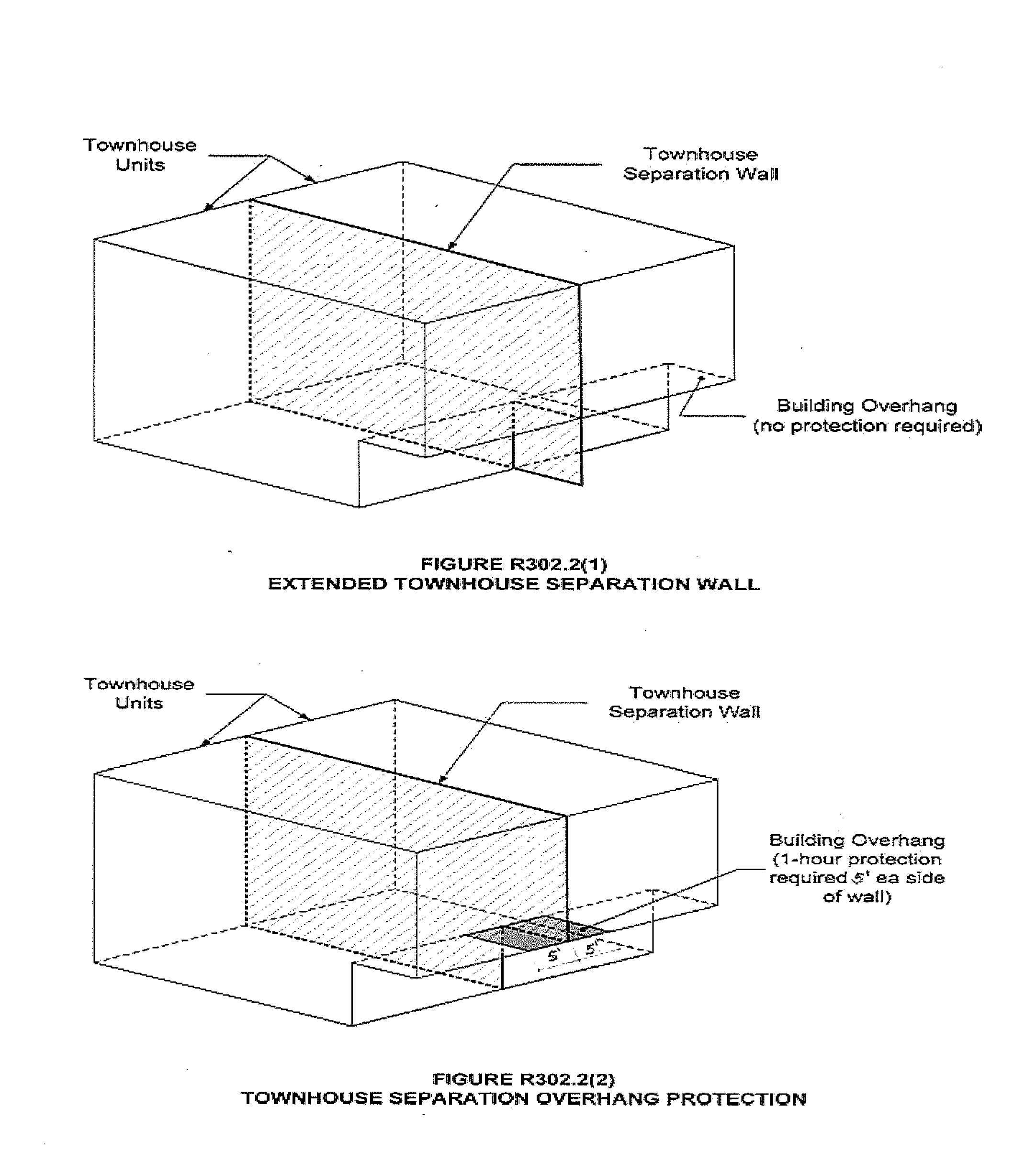
R302.2.3Continuity. The fire-resistance-rated wall or assembly separating townhouse units shall be continuous from the foundation to the underside of the roof sheathing, deck or slab. The fire-resistance rating shall extend the full length of the wall or assembly, including wall extensions through and separating attached enclosed accessory structures.
Where a story extends beyond the exterior wall of a story below:
1. The fire-resistance-rated wall or assembly shall extend to the outside edge of the upper story (see Figure R302.2(1)); or
2. The underside of the exposed floor-ceiling assembly shall be protected as required for projections in Section R302 (see Figure R302.2(2)).
R302.2.4 Parapets for townhouses. Parapets constructed in accordance with Section R302.2.5 shall be constructed for townhouses as an extension of exterior walls or common walls separating townhouse units in accordance with the following:
1. Where roof surfaces adjacent to the wall or walls are at the same elevation, the parapet shall extend not less than 30 inches (762 mm) above the roof surfaces.
2. Where roof surfaces adjacent to the wall or walls are at different elevations and the higher roof is not more than 30 inches (762 mm) above the lower roof, the parapet shall extend not less than 30 inches (762 mm) above the lower roof surface.
EXCEPTION: | A parapet is not required in the preceding two cases where the roof covering complies with a minimum Class C rating as tested in accordance with ASTM E108 or UL 790 and the roof decking or sheathing is of noncombustible materials or fire retardant-treated wood for a distance of 4 feet (1219 mm) on each side of the wall or walls, or one layer of 5/8-inch (15.9 mm) Type X gypsum board is installed directly beneath the roof decking or sheathing, supported by not less than nominal 2-inch (51 mm) ledgers attached to the sides of the roof framing members, for a distance of not less than 4 feet (1219 mm) on each side of the wall or walls and any openings or penetrations in the roof are not within 4 feet (1219 mm) of the common walls. Fire retardant-treated wood shall meet the requirements of Sections R802.1.5 and R803.2.1.2. |
3. A parapet is not required where roof surfaces adjacent to the wall or walls are at different elevations and the higher roof is more than 30 inches (762 mm) above the lower roof. The common wall construction from the lower roof to the underside of the higher roof deck shall have not less than a 1-hour fire-resistance rating. The wall shall be rated for exposure from both sides.
TABLE R302.1(1)
EXTERIOR WALLS
No Change to the Table
a | The fire-resistance rating shall be permitted to be reduced to 0 hours on the underside of the eave overhang if fireblocking is provided from the wall top plate to the underside of the roof sheathing. |
b | The fire-resistance rating shall be permitted to be reduced to 0 hours on the underside of the rake overhang where ventilation openings are not installed in the rake overhang or in walls that are common to attic areas. |
TABLE R302.1(2)
EXTERIOR WALLS - DWELLINGS WITH FIRE SPRINKLERS
No Change to the Table
a | For residential subdivisions where all dwellings are equipped throughout with an automatic sprinkler system installed in accordance with Section P2904, the fire separation distance for exterior walls not fire-resistance-rated and for fire-resistance-rated projections shall be permitted to be reduced to 0 feet, and unlimited unprotected openings and penetrations shall be permitted, where the adjoining lot provides an open setback yard that is 6 feet or more in width on the opposite side of the property line. |
b | The fire-resistance rating shall be permitted to be reduced to 0 hours on the underside of the eave overhang if fireblocking is provided from the wall top plate to the underside of the roof sheathing. |
c | The fire-resistance rating shall be permitted to be reduced to 0 hours on the underside of the rake overhang where ventilation openings are not installed in the rake overhang or in walls that are common to attic areas. |
R302.3 Two-family dwellings. Wall and floor/ceiling assemblies separating dwelling units in two-family dwellings shall be constructed in accordance with Section R302.3.1 through R302.3.5. One accessory dwelling unit constructed within an existing dwelling unit need not be considered a separated dwelling unit in a two-family dwelling where all required smoke alarms, in the accessory dwelling unit and the primary dwelling unit, are interconnected in such a manner that the actuation of one alarm will activate all alarms in both the primary dwelling unit and the accessory dwelling unit.
R302.3.1 Separation.Dwelling units in two-family dwellings shall be separated from each other by wall and floor assemblies having not less than a 1-hour fire-resistance rating where tested in accordance with ASTM E119, UL 263 or Section 703.2.2 of the International Building Code.
EXCEPTIONS: | 1. A fire-resistance rating of 1/2 hour shall be permitted in buildings equipped throughout with an automatic sprinkler system installed in accordance with ((NFPA 13D))Section 2904. |
| 2. Where an accessory dwelling unit is added within an existing single-family residence to create a two-family dwelling, fire-rated separation between the accessory dwelling unit and the primary dwelling unit is not required when all required smoke alarms are interconnected in such a manner that the actuation of one alarm will activate all alarms in both the primary dwelling unit and the accessory dwelling unit. |
R302.3.2 Continuity. Fire-resistance-rated floor/ceiling and wall assemblies shall extend to and be tight against the exterior wall, and wall assemblies shall extend from the foundation to the underside of the roof sheathing.
EXCEPTION: | Wall assemblies need not extend through attic spaces where the ceiling is protected by not less than 5/8-inch (15.9 mm) Type X gypsum board, an attic draft stop constructed as specified in Section R302.12.1 is provided above and along the wall assembly separating the dwellings and the structural framing supporting the ceiling is protected by not less than 1/2-inch (12.7 mm) gypsum board or equivalent. |
R302.3.3 Supporting construction. Where floor/ceiling assemblies are required to be fire-resistance rated by Section R302.3, the supporting construction of such assemblies shall have an equal or greater fire-resistance rating.
R302.3.4((.)) Openings protection between two-family dwellings. Openings in the common fire-resistance-rated wall assembly located between units of a two-family dwelling shall be equipped with not less than a 45-minute fire-rated door assembly equipped with a self-closing or automatic-closing device.
EXCEPTION: | A 20-minute fire-rated door assembly is permitted in buildings equipped throughout with an automatic sprinkler system installed in accordance with Section P2904 or NFPA 13D. |
R302.3.5 Shared accessory rooms. Shared accessory rooms shall be separated from each individual dwelling unit in accordance with Table R302.3.5. Openings between the shared accessory room and the dwelling unit shall comply with Section R302.3.5.1. Attachment of gypsum board shall comply with Table R702.3.5.
R302.3.5.1 Opening protection. Openings from a shared accessory room or area directly into a room used for sleeping purposes shall not be permitted. Other openings between the shared accessory room or area shall be equipped with solid wood doors not less than 1 3/8 inches in thickness, solid or honeycomb core steel doors not less than 1 3/8 inches thick, or a fire door assembly with a 20-minute fire-protection rating, equipped with a self-closing or automatic-closing device.
R302.3.5.2 Duct penetration. Ducts penetrating the walls or ceilings separating the dwelling from the shared accessory room shall be constructed of a minimum No. 26 gage (0.48 mm) sheet steel or other approved material and shall not have openings into the shared accessory room.
R302.3.5.3 Other penetrations. Penetrations through the walls, ceiling, and floor level separation required in Section R302.3.5 shall be protected as required by Section R302.11, Item 4.
TABLE R302.3.5
DWELLING-SHARED ACCESSORY ROOM SEPARATION
SEPARATION | MATERIAL |
From the dwelling units and attics. | Not less than 1/2-inch gypsum board or equivalent applied to the accessory room side wall. |
From habitable rooms above or below the shared accessory room. | Not less than 5/8-inch Type X gypsum board or equivalent. |
Structures supporting floor/ceiling assemblies used for separation required by this section. | Not less than 1/2-inch gypsum board or equivalent. |
R302.13 Fire protection of floors. Floor assemblies that are not required elsewhere in this code to be fire-resistance rated, shall be provided with a 1/2-inch (12.7 mm) gypsum wallboard membrane, 5/8-inch (16 mm) wood structural panel membrane, or equivalent on the underside of the floor framing member. Penetrations or openings for ducts, vents, electrical outlets, lighting, devices, luminaires, wires, speakers, drainage, piping and similar openings or penetrations shall be permitted.
EXCEPTIONS: | 1. Floor assemblies located directly over a space protected by an automatic sprinkler system in accordance with Appendix WU, NFPA 13D, or other approved equivalent sprinkler system. |
| 2. Floor assemblies located directly over a crawl space not intended for storage or fuel-fired appliances. |
| 3. Portions of floor assemblies shall be permitted to be unprotected when complying with the following: |
| 3.1. The aggregate area of the unprotected portions shall not exceed 80 square feet per story. |
| 3.2. Fire blocking in accordance with Section R302.11.1 is installed along the perimeter of the unprotected portion to separate the unprotected portion from the remainder of the floor assembly. |
| 4. Wood floor assemblies using ((dimensional))dimension lumber or structural composite lumber with a cross sectional area equal to or greater than 2-inch by 10-inch nominal dimension, or other approved floor assemblies demonstrating equivalent fire performance. |
Reviser's note: The bracketed material preceding the section above was supplied by the code reviser's office.
AMENDATORY SECTION(Amending WSR 23-02-058 and 23-12-104 [20-03-023], filed 1/3/23 and 6/7/23 [1/6/20], effective 10/29/23 [7/1/20])
WAC 51-51-0303Section R303—Light, ventilation and heating.
R303.1 Natural light. All habitable rooms shall have an aggregate glazing area of not less than 8 percent of the floor area of such rooms.
EXCEPTION: | The glazed areas need not be installed in rooms where artificial light is provided capable of producing an average illumination of 6 footcandles (65 lux) over the area of the room at a height of 30 inches (762 mm) above the floor level. |
R303.2 Adjoining rooms. For the purpose of determining light requirements, any room shall be considered as a portion of an adjoining room when at least one-half of the area of the common wall is open and unobstructed and provides an opening of not less than one-tenth of the floor area of the interior room but not less than 25 square feet (2.3 m2).
EXCEPTION: | Openings required for light shall be permitted to open into a sunroom with thermal isolation or a patio cover, provided there is an openable area between the adjoining room and the sunroom or a patio cover of not less than one-tenth of the floor area of the interior room but not less than 20 square feet (2 m2). |
R303.3 Bathrooms. This section is not adopted.
R303.4 Minimum ventilation performance. Dwelling units shall be equipped with local exhaust and whole-house ventilation systems designed and installed as specified in Section M1505.
EXCEPTION: | Additions with less than 500 square feet of conditioned floor area are exempt from the requirements in this Code for Whole-House Ventilation Systems. |
R303.5.1 Intake openings. Mechanical and gravity outdoor air intake openings shall be located a minimum of 10 feet (3048 mm) from any hazardous or noxious contaminant, such as vents, chimneys, plumbing vents, streets, alleys, parking lots and loading docks, except as otherwise specified in this code.
For the purpose of this section, the exhaust from dwelling unit toilet rooms, bathrooms and kitchens shall not be considered as hazardous or noxious.
EXCEPTIONS: | 1. The 10-foot (3048 mm) separation is not required where the intake opening is located 3 feet (914 mm) or greater below the contaminant source. |
| 2. Vents and chimneys serving fuel-burning appliances shall be terminated in accordance with the applicable provisions of Chapters 18 and 24. |
| 3. Clothes dryer exhaust ducts shall be terminated in accordance with Section M1502.3. |
R303.5.2 Exhaust openings. Exhaust air shall not be directed onto walkways. All exhaust ducts shall terminate outside the building. Terminal elements shall have at least the equivalent net free area of the duct work.
R303.5.2.1 Exhaust ducts. Exhaust ducts shall be equipped with back-draft dampers. All exhaust ducts in unconditioned spaces shall be insulated to a minimum of R-4.
R303.7 Interior stairway illumination. Interior stairways shall be provided with an artificial light source to illuminate the landings and treads. Stairway illumination shall receive primary power from the building wiring. The light source shall be capable of illuminating treads and landings to levels not less than 1 foot-candle (11 lux) measured at the center of treads and landings. There shall be a wall switch at each floor level to control the light source where the stairway has six or more risers.
EXCEPTION: | A switch is not required where remote, central or automatic control of lighting is provided. |
R303.8 Exterior stairway illumination. Exterior stairways shall be provided with an artificial light source located at the top landing of the stairway. Stairway illumination shall receive primary power from the building wiring. Exterior stairways providing access to a basement from the outdoor grade level shall be provided with an artificial light source located at the bottom landing of the stairway.
R303.9 Required glazed openings. Required glazed openings shall open directly onto a street or public alley, or a yard or court located on the same lot as the building.
EXCEPTIONS: | 1. Required glazed openings that face into a roofed porch where the porch abuts a street, yard or court are permitted where the longer side of the porch is not less than 65 percent unobstructed and the ceiling height is not less than 7 feet (2134 mm). |
| 2. Eave projections shall not be considered as obstructing the clear open space of a yard or court. |
| 3. Required glazed openings that face into the area under a deck, balcony, bay or floor cantilever are permitted where an unobstructed pathway of not less than 36 inches (914 mm) in height, 36 inches (914 mm) in width, and no greater than 60 inches (1524 mm) in length is provided and opens to a yard or court. The pathway shall be measured from the exterior face of the glazed opening, or if the glazed opening is in a window well, at the window well wall furthest from the exterior face of the glazed opening. |
R303.10 Required heating. When the winter design temperature in Table R301.2(((1))) is below 60°F (16°C), every dwelling unit shall be provided with heating facilities capable of maintaining a minimum room temperature of 68°F (20°C) at a point 3 feet (914 mm) above the floor and 2 feet (610 mm) from exterior walls in all habitable rooms at design temperature. The installation of one or more portable heaters shall not be used to achieve compliance with this section.
EXCEPTION: | Unheated recreational tents or yurts not exceeding 500 square feet provided it is not occupied as a permanent dwelling. |
R303.10.1 Definitions. For the purposes of this section only, the following definitions apply.
DESIGNATED AREAS are those areas designated by a county to be an urban growth area in chapter
36.70A RCW and those areas designated by the U.S. Environmental Protection Agency as being in nonattainment for particulate matter.
SUBSTANTIALLY REMODELED means any alteration or restoration of a building exceeding 60 percent of the appraised value of such building within a 12-month period. For the purpose of this section, the appraised value is the estimated cost to replace the building and structure in kind, based on current replacement costs.
R303.10.2 Primary heating source. Primary heating sources in all new and substantially remodeled buildings in designated areas shall not be dependent upon wood stoves.
R303.10.3 Solid fuel burning devices. No new or used solid fuel burning device shall be installed in new or existing buildings unless such device is U.S. Environmental Protection Agency certified or exempt from certification by the United States Environmental Protection Agency and conforms with RCW
70A.15.1005,
70A.15.3500,
70A.15.3510, and
70A.15.3530.
EXCEPTIONS: | 1. Wood cook stoves. |
| 2. Antique wood heaters manufactured prior to 1940. |
Reviser's note: The bracketed material preceding the section above was supplied by the code reviser's office.
AMENDATORY SECTION(Amending WSR 23-02-058 and 23-12-104 [20-03-023], filed 1/3/23 and 6/7/23 [1/6/20], effective 10/29/23 [7/1/20])
WAC 51-51-0311Section R311—Means of egress.
R311.4 Vertical egress. Egress from habitable levels including habitable attics and basements not provided with an egress door in accordance with Section R311.2 shall be by a ramp in accordance with Section R311.8 or a stairway in accordance with Section R311.7.
EXCEPTION: | Stairways, alternating tread devices, ship's ladders, or ladders within an individual dwelling unit or sleeping unit used for access to areas of 200 square feet (18.6 m2) or less, are exempt from the requirements of Sections R311.4 and R311.7, where such devices do not provide exclusive access to a kitchen or bathroom. Such areas shall not be located more than 10 feet (3048 mm) above the finished floor of the space below. |
R311.7.11 Alternating tread devices.Alternating tread devices shall not be used as an element of a means of egress. Alternating tread devices shall be permitted provided that a required means of egress stairway or ramp serves the same space at each adjoining level or where a means of egress is not required. The clear width at and below the handrails shall be not less than 20 inches (508 mm).
R311.7.12 Ship's ladders. Ship's ladders shall not be used as an element of a means of egress. Ship's ladders shall be permitted provided that a required means of egress stairway or ramp serves the same space at each adjoining level or where a means of egress is not required. The clear width at and below the handrails shall be not less than 20 inches (508 mm).
Reviser's note: The bracketed material preceding the section above was supplied by the code reviser's office.
AMENDATORY SECTION(Amending WSR 23-02-058 and 23-12-104, filed 1/3/23 and 6/7/23, effective 10/29/23)
WAC 51-51-0312Section R312—Guards and window fall protection.
R312.1.1 Where required.Guards shall be provided for those portions of open-sided walking surfaces, including floors, mezzanines, lofts in accordance with Section R333, stairs, ramps, and landings, that are located more than 30 inches (762 mm) measured vertically to the floor or grade below at any point within 36 inches (914 mm) horizontally to the edge of the open side. Insect screening shall not be considered as a guard.
R312.1.2 Height. Required guards at open-sided walking surfaces, including stairs, porches, balconies or landings, shall be not less than 36 inches (914 mm) in height as measured vertically above the adjacent walking surface or the line connecting the nosings.
EXCEPTIONS: | 1. Guards on the open sides of stairs shall have a height of not less than 34 inches (864 mm) measured vertically from a line connecting the nosings. |
| 2. Where the top of the guard serves as a handrail on the open sides of stairs, the top of the guard shall be not less than 34 inches (864 mm) and not more than 38 inches (965 mm) as measured vertically from a line connecting the nosings. |
| 3. In areas with ceiling heights of 7 feet (2134 mm) or less in lofts constructed in accordance with Section R333, guards shall not be less than 36 inches (914 mm) in height or one-half of the clear height from the loft floor to the loft ceiling, whichever is less. |
Reviser's note: The above section was filed as an amendatory section; however, this section will not come into effect as a new section until October 29, 2023.
AMENDATORY SECTION(Amending WSR 23-02-058 and 23-12-104 [20-21-041], filed 1/3/23 and 6/7/23 [10/13/20], effective 10/29/23 [11/13/20])
WAC 51-51-0314Section R314—Smoke alarms and heat detection.
R314.1 General. Smoke alarms, heat detectors, and heat alarms shall comply with NFPA 72 and this section.
R314.1.1 Listings. Smoke alarms shall be listed in accordance with UL 217. Heat detectors and heat alarms shall be listed for the intended application. Combination smoke and carbon monoxide alarms shall be listed in accordance with UL 217 and UL 2034.
R314.2 Where required. Smoke alarms, heat detectors, and heat alarms shall be provided in accordance with this section.
R314.2.1 New construction. Smoke alarms shall be provided in dwelling units. A heat detector or heat alarm shall be provided in new attached garages.
R314.2.2 Alterations, repairs and additions. Where alterations, repairs or additions requiring a permit occur, or where one or more sleeping rooms are added or created in existing dwellings, or where an accessory dwelling unit is created within an existing dwelling unit, each dwelling unit shall be equipped with smoke alarms as required for new dwellings.
EXCEPTIONS: | 1. Work involving the exterior surfaces of dwellings, such as the replacement of roofing or siding, the addition or replacement of windows or doors, or the addition of a porch or deck are exempt from the requirements of this section. |
| 2. Installation, alteration or repairs of plumbing, electrical or mechanical systems are exempt from the requirements of this section. |
R314.2.3 New attached garages. A heat detector or heat alarm rated for the ambient outdoor temperatures and humidity shall be installed in new garages that are attached to or located under new and existing dwellings. Heat detectors and heat alarms shall be installed in a central location and in accordance with the manufacturer's instructions.
EXCEPTION: | Heat detectors and heat alarms shall not be required in dwellings without commercial power. |
R314.3 Location. Smoke alarms shall be installed in the following locations:
1. In each sleeping room.
2. Outside each separate sleeping area in the immediate vicinity of the bedrooms.
3. On each additional story of the dwelling, including basements and habitable attics but not including crawl spaces and uninhabitable attics. In dwellings or dwelling units with split levels and without an intervening door between the adjacent levels, a smoke alarm installed on the upper level shall suffice for the adjacent lower level provided that the lower level is less than one full story below the upper level.
4. Smoke alarms shall be installed not less than 3 feet (914 mm) horizontally from the door or opening of a bathroom that contains a bathtub or shower unless this would prevent placement of a smoke alarm required by Section R314.3.
5. In napping areas in a family home child care.
6. In the hallway and in the room open to the hallway in dwelling units where the ceiling height of a room open to a hallway serving bedrooms exceeds that of the hallway by 24 inches (610 mm) or more.
7. Within the room to which a loft is open, in the immediate vicinity of the loft.
R314.4 Interconnection. Where more than one smoke alarm is required to be installed within an individual dwelling unit in accordance with Section ((R314.2))R314.3, the alarm devices shall be interconnected in such a manner that the actuation of one alarm will activate all of the alarms in the individual dwelling unit. Where an accessory dwelling unit is created within an existing dwelling unit all required smoke alarms, in the accessory dwelling unit and the primary dwelling unit, shall be interconnected in such a manner that the actuation of one alarm will activate all alarms in both the primary dwelling unit and the accessory dwelling unit. Physical interconnection of smoke alarms shall not be required where listed wireless alarms are installed and all alarms sound upon activation of one alarm.
EXCEPTION: | Smoke alarms and alarms installed to satisfy Section R314.4.1 shall not be required to be interconnected to existing smoke alarms where such existing smoke alarms are not interconnected or where such new smoke alarm or alarm is not capable of being interconnected to the existing smoke alarms. |
R314.4.1 Heat detection interconnection. Heat detectors and heat alarms shall be connected to an alarm or a smoke alarm that is installed in the dwelling. Alarms and smoke alarms that are installed for this purpose shall be located in a hallway, room, or other location that will provide occupant notification.
R314.6 Power source. Smoke alarms, heat alarms, and heat detectors shall receive their primary power from the building wiring where such wiring is served from a commercial source and, where primary power is interrupted, shall receive power from a battery. Wiring shall be permanent and without a disconnecting switch other than those required for overcurrent protection.
EXCEPTIONS: | 1. Smoke alarms shall be permitted to be battery operated where installed in buildings without commercial power. |
| 2. Smoke alarms installed in accordance with Section R314.2.2 shall be permitted to be battery powered. |
Reviser's note: The bracketed material preceding the section above was supplied by the code reviser's office.
AMENDATORY SECTION(Amending WSR 20-21-041, filed 10/13/20, effective 11/13/20)
WAC 51-51-03240Section R324—Solar energy systems.
R324.3 Photovoltaic systems. Installation, modification, or alteration of solar photovoltaic power systems shall comply with this section and the
International Fire Code. Section R104.11 ((
alternate))
alternative materials and methods of this code shall be considered when approving the installation of solar photovoltaic power systems. Photovoltaic systems shall be designed and installed in accordance with Sections R324.3.1 through R324.6 and chapter
19.28 RCW. Inverters shall be listed and labeled in accordance with UL 1741. Systems connected to the utility grid shall use inverters listed for utility interaction.
EXCEPTION: | Detached, nonhabitable Group U structures shall not be subject to the requirements of this section for structural and fire safety. |
R324.4 Rooftop-mounted photovoltaic systems. Rooftop-mounted photovoltaic panel systems installed on or above the roof covering shall be designed and installed in accordance with Section R907.
EXCEPTION: | The roof structure shall be deemed adequate to support the load of the rooftop solar photovoltaic system if all of the following requirements are met: |
| 1. The solar photovoltaic panel system shall be designed for the wind speed of the local area, and shall be installed per the manufacturer's specifications. |
| 2. The ground snow load does not exceed 70 pounds per square foot (3.35 kPa). |
| 3. The total dead load of modules, supports, mountings, raceways, and all other appurtenances weigh no more than 4 pounds per square foot (19.5 kg/m2). |
| 4. Photovoltaic modules are not mounted higher than 18 inches (457 mm) above the surface of the roofing to which they are affixed. |
| 5. Supports for solar modules are to be installed to spread the dead load across as many roof-framing members as needed, so that no point load exceeds 50 pounds (22.7 kg). |
R324.7.1 This section is not adopted.
AMENDATORY SECTION(Amending WSR 23-02-058 and 23-12-104 [20-03-023], filed 1/3/23 and 6/7/23 [1/6/20], effective 10/29/23 [7/1/20])
WAC 51-51-0326Section R326—Habitable attics.
R326.1 General.Habitable attics shall comply with Sections ((R326))R326.1 through R326.4.
EXCEPTION: | Lofts in dwelling units and sleeping units shall be permitted to comply with Section R333, subject to the limitations in Section R333.1. |
Reviser's note: The bracketed material preceding the section above was supplied by the code reviser's office.
AMENDATORY SECTION(Amending WSR 20-03-023, filed 1/6/20, effective 7/1/20)
WAC 51-51-0330Section R330—Adult family homes.
R330.1 General. This section shall apply to all newly constructed adult family homes and all existing single-family homes being converted to adult family homes. This section shall not apply to those adult family homes licensed by the state of Washington department of social and health services prior to July 1, 2001.
R330.2 Reserved.
R330.3 Sleeping room classification. Each sleeping room in an adult family home shall be classified as:
1. Type S - Where the means of egress contains stairs, elevators, or platform lifts.
2. Type NS1 - Where one means of egress is at grade level or a ramp constructed in accordance with Section R330.9 is provided.
3. Type NS2 - Where two means of egress are at grade level or ramps constructed in accordance with Section R330.9 are provided.
R330.4 Types of locking devices and door activation. All bedroom and bathroom doors shall be openable from the outside when locked.
Every closet shall be readily openable from the inside.
Operable parts of door handles, pulls, latches, locks, and other devices installed in adult family homes shall be operable with one hand and shall not require tight grasping, pinching or twisting of the wrist. Pocket doors shall have graspable hardware available when in the closed or open position.
The force required to activate operable parts shall be 5.0 pounds (22.2 N) maximum. Required exit doors shall have no additional locking devices.
Required exit door hardware shall unlock inside and outside mechanisms when exiting the building allowing reentry into the adult family home without the use of a key, tool or special knowledge.
R330.5 Smoke and carbon monoxide alarm requirements. All adult family homes shall be equipped with smoke and carbon monoxide alarms installed as required in Sections R314 and R315.1. Alarms shall be installed in such a manner so that the detection device warning is audible from all areas of the dwelling upon activation of a single alarm.
R330.6 Escape windows and doors. Every sleeping room shall be provided with emergency escape and rescue windows as required by Section R310. No alternatives to the sill height such as steps, raised platforms or other devices placed by the openings will be approved as meeting this requirement.
R330.7 Fire apparatus access roads and water supply for fire protection. Adult family homes shall be served by fire apparatus access roads and water supplies meeting the requirements of the local jurisdiction.
R330.8 Grab bar general requirements. Where facilities are designated for use by adult family home clients, grab bars for water closets, bathtubs, and shower stalls shall be installed according to this section.
R330.8.1 Grab bar cross section. Grab bars with a circular cross section shall have an outside diameter of 1 1/4 inch (32 mm) minimum and 2 inches (50 mm) maximum. Grab bars with noncircular cross section shall have a cross section dimension of 2 inches (50 mm) maximum and a perimeter dimension of 4 inches (102 mm) minimum and 4 5/8 inches maximum.
R330.8.2 Grab bar installation. Grab bars shall have a spacing of 1 1/2 inch (32 mm) between the wall and the bar. Projecting objects, control valves and bathtub or shower stall enclosure features above, below and at the ends of the grab bar shall have a clear space of 1 1/2 inch (32 mm) to the grab bar.
EXCEPTION: | Swing-up grab bars shall not be required to meet the 1 1/2 inch (32 mm) spacing requirement. |
Grab bars shall have a structural strength of 250 pounds applied at any point on the grab bar, fastener, mounting device or supporting structural member. Grab bars shall not be supported directly by any residential grade fiberglass bathing or showering unit. Acrylic bars found in bathing units shall be removed.
Fixed position grab bars, when mounted, shall not rotate, spin or move and have a graspable surface finish.
R330.8.3 Grab bars at water closets. Water closets shall have grab bars mounted on both sides. Grab bars can be a combination of fixed position and swing-up bars. Grab bars shall meet the requirements of Section R330.8. Grab bars shall mount between 33 inches (838 mm) and 36 inches (914 mm) above floor grade. Centerline distance between grab bars, regardless of type used, shall be between 25 inches (635 mm) minimum and 30 inches (762 mm) maximum.
R330.8.3.1 Fixed position grab bars. Fixed position grab bars shall be a minimum of 36 inches (914 mm) in length and start 12 inches (305 mm) from the rear wall.
R330.8.3.2 Swing-up grab bars. Swing-up grab bars shall be a minimum of 28 inches (711 mm) in length from the rear wall.
R330.8.4 Grab bars at bathtubs. Horizontal and vertical grab bars shall meet the requirements of Section R330.8.
R330.8.4.1 Vertical grab bars. Vertical grab bars shall be a minimum of 18 inches (457 mm) long and installed at the control end wall and head end wall. Grab bars shall mount within 4 inches (102 mm) of the exterior of the bathtub edge or within 4 inches (102 mm) within the bathtub. The bottom end of the bar shall start between 36 inches (914 mm) and 42 inches (1067 mm) above floor grade.
EXCEPTION: | The required vertical grab bar can be substituted with a floor to ceiling grab bar meeting the requirements of Section R325.8 at the control end and head end entry points. |
R330.8.4.2 Horizontal grab bars. Horizontal grab bars shall be provided at the control end, head end, and the back wall within the bathtub area. Grab bars shall be mounted between 33 inches (838 mm) and 36 inches (914 mm) above floor grade. Control end and head end grab bars shall be 24 inches (610 mm) minimum in length. Back wall grab bars shall be 36 inches (914 mm) minimum in length.
R330.8.5 Grab bars at shower stalls. Where shower stalls are provided to meet the requirements for bathing facilities, grab bars shall meet the requirements of Section R330.8.
EXCEPTION: | Shower stalls with permanent built-in seats are not required to have vertical or horizontal grab bars at the seat end wall. A vertical floor to ceiling grab bar shall be installed within 4 inches of the exterior of the shower aligned with the nose of the built-in seat. |
R330.8.5.1 Vertical grab bars. Vertical grab bars shall be 18 inches (457 mm) minimum in length and installed at the control end wall and head end wall. Vertical bars shall be mounted within 4 inches (102 mm) of the exterior of the shower stall or within 4 inches (102 mm) inside the shower stall. The bottom end of vertical bars mount between 36 inches (914 mm) and 42 inches (1067 mm) above floor grade.
R330.8.5.2 Horizontal grab bars. Horizontal grab bars shall be installed on all sides of the shower stall mounted between 33 inches (838 mm) and 36 inches (914 mm) above the floor grade. Horizontal grab bars shall be a maximum of 6 inches (152 mm) from adjacent walls. Horizontal grab bars shall not interfere with shower control valves.
R330.9 Ramps. All interior and exterior ramps, when provided, shall be constructed in accordance with Section R311.8 with a maximum slope of 1 vertical to 12 horizontal. The exception to Section R311.8.1 is not allowed for adult family homes. Handrails shall be installed in accordance with Section R330.9.1.
R330.9.1 Handrails for ramps. Handrails shall be installed on both sides of ramps between the slope of 1 vertical to 12 horizontal and 1 vertical and 20 horizontal in accordance with Sections R311.8.3.1 through R311.8.3.3.
R330.10 Stair treads and risers. Stair treads and risers shall be constructed in accordance with Section R311.7.5. Handrails shall be installed in accordance with Section R330.10.1.
R330.10.1 Handrails for treads and risers. Handrails shall be installed on both sides of treads and risers numbering from one riser to multiple risers. Handrails shall be installed in accordance with Sections R311.7.8.1 through R311.7.8.4.
R330.11 Shower stalls. Where provided to meet the requirements for bathing facilities, the minimum size of shower stalls for an adult family home shall be 30 inches (762 mm) deep by 48 inches (1219 mm) long.
AMENDATORY SECTION(Amending WSR 20-03-023, filed 1/6/20, effective 7/1/20)
WAC 51-51-0331Section R331—Family home child care.
R331 Family home child care. For family home child care with more than six children, each floor level used for family child care purposes shall be served by two remote means of egress. Exterior exit doors shall be operable from the inside without the use of keys or any special knowledge or effort.
Basements located more than 4 feet below grade level shall not be used for family home child care unless one of following conditions exist:
1. Stairways from the basement open directly to the exterior of the building without entering the first floor;
2. One of the two required means of egress discharges directly to the exterior from the basement level, and a self-closing door is installed at the top or bottom of the interior stair leading to the floor above;
3. One of the two required means of egress is an operable window or door, approved for emergency escape or rescue, that opens directly to a public street, public alley, yard or exit court; or
4. A residential sprinkler system is provided throughout the entire building in accordance with NFPA 13d.
Floors located more than 4 feet above grade level shall not be occupied by children in family home child care.
EXCEPTIONS: | 1. Use of toilet facilities while under supervision of an adult staff person; |
| 2. Family home child care may be allowed on the second story if one of the following conditions exists: |
| 2.1. Stairways from the second story open directly to the exterior of the building without entering the first floor; |
| 2.2. One of the two required means of egress discharges directly to the exterior from the second story level, and a self-closing door is installed at the top or bottom of the interior stair leading to the floor below; or |
| 2.3. A residential sprinkler system is provided throughout the entire building in accordance with NFPA 13d. |
Every sleeping or napping room in a family home child care shall have at least one operable window for emergency rescue.
EXCEPTION: | Sleeping or napping rooms having doors leading to two separate means of egress, or a door leading directly to the exterior of the building. |
Rooms or spaces containing a commercial-type cooking kitchen, boiler, maintenance shop, janitor closet, laundry, woodworking shop, flammable or combustible storage, or painting operation shall be separated from the family home child care area by at least 1-hour ((fire-resistive))fire-resistant construction.
EXCEPTION: | A ((fire-resistive))fire-resistant separation shall not be required where the food preparation kitchen contains only a domestic cooking range, and the preparation of food does not result in the production of smoke or grease laden vapors. |
AMENDATORY SECTION(Amending WSR 23-02-058 and 23-12-104, filed 1/3/23 and 6/7/23, effective 10/29/23)
WAC 51-51-0333Section R333—Lofts.
R333.1 General. Where provided in dwelling units or sleeping units, lofts shall comply with this code as modified by Sections R333.1 through R333.5. Lofts constructed in compliance with this section shall be considered a portion of the story below. Such lofts shall not contribute to the number of stories as regulated by this code.
EXCEPTION: | Lofts need not comply with Section R333 where they meet any of the following conditions: |
| 1. The loft has a maximum depth of less than 3 feet (914 mm). |
| 2. The loft has a floor area of less than 35 square feet (3.3 m2). |
| 3. The loft is not provided with a permanent means of egress. |
R333.2 Loft limitations. Lofts shall comply with the following conditions:
1. The loft floor area shall be less than 70 square feet (6.5 m2).
2. The loft ceiling height shall not exceed 7 feet (2134 mm) for more than one half of the loft floor area.
The provisions of Sections R333.3 through R333.5 shall not apply to lofts that do not comply with Items 1 and 2 of this section.
R333.3 Loft ceiling height. The ceiling height below a loft shall not be less than 7 feet (2134 mm). The ceiling height above the finished floor of the loft shall not be less than 3 feet (914 mm). Portions of the loft with a sloped ceiling measuring less than 3 feet (914 mm) from the finished floor to the finished ceiling shall not contribute to the loft floor area.
R333.4 Loft area. The aggregate area of all lofts and mezzanines within a room shall comply with Section R325.3.
EXCEPTION: | The area of a single loft located within a dwelling unit or sleeping unit equipped with an automatic sprinkler system in accordance with Section P2904 shall not be greater than two-thirds of the area of the room in which it is located, provided that no other lofts or mezzanines are open to the room in which the loft is located. |
R333.5 Permanent egress for lofts. Where a permanent means of egress is provided for lofts, the means of egress shall comply with Section R311 as modified by Section R333.5.1.
R333.5.1 Ceiling height at loft means of egress. A minimum ceiling height of 3 feet (914 mm) shall be provided for the entire width of the means of egress from the loft.
Reviser's note: The above section was filed as an amendatory section; however, this section will not come into effect as a new section until October 29, 2023.
AMENDATORY SECTION(Amending WSR 23-02-058 and 23-12-104 [20-03-023], filed 1/3/23 and 6/7/23 [1/6/20], effective 10/29/23 [7/1/20])
WAC 51-51-0403Section R403—Footings.
R403.1.1 Minimum size. The minimum width, W, and thickness, T, for concrete footings shall be in accordance with Tables R403.1(1) through R403.1(3) and Figure R403.1(1) or R403.1.3, as applicable, but not less than 12 inches (305 mm) in width and 6 inches (152 mm) in depth. The footing width shall be based on the load-bearing value of the soil in accordance with Table R401.4.1. Footing projections, P, shall be not less than 2 inches (51 mm) and shall not exceed the thickness of the footing. Footing thickness and projection for fireplaces shall be in accordance with Section R1001. The size of footings supporting piers and columns shall be based on the tributary load and allowable soil pressure in accordance with Table R401.4.1. Footings for wood foundations shall be in accordance with the details set forth in Section R403.2, and Figures R403.1(2) and R403.1(3). Footings for precast foundation shall be in accordance with the details set forth in Section R403.4, Table R403.4, and Figures R403.4(1) and R403.4(2).
EXCEPTION: | Light-frame construction shall be permitted to have minimum footing size in accordance with Figures R403.1.1(1) through R403.1.1(4) in lieu of that determined by Table R403.1(1). |
Figure R403.1.1(1)
Alternative Minimum Footing Size for Light-Frame Construction a,b,c,d,e,f,g,h,i
20 PSF Snow Load
Notes: | a | The minimum footing size is based on the following assumptions: Material weights per Section R301.2.2.2.1 and soil density = 120 pcf. Wood-framed walls = 10 foot; crawlspace stem wall = 6 inches × 36 inches; basement wall = 8 inches × 120 inches. Total load (TL) equal to the maximum of three load combinations: LC1=D+L, LC2=D+S and LC3=D=0.75(L+S), where D=dead load, L=live load, S=snow load. TL=max (LC1, LC2, LC3). |
| b | Use tributary span of floor and roof. Figure may be used to size exterior and interior footings. |
| c | Add 4 feet to tributary floor span for each wood-framed wall above first level (i.e., ((4'))4 feet for 2-story, ((8'))8 feet for 3-story). |
| d | Multiply floor span by 1.25 for interior footings supporting continuous joists. |
| e | Multiply footing width by (1500 psf/capacity) for soil capacity other than 1500 psf. See Section R403.1.1 for thickness. |
| f | Dashed line may be used for interior footing size only. |
| g | Use footing size indicated on line above the span combination used. |
| h | For span combinations above the upper line, a design professional is required. |
| i | Interpolation between footing sizes is allowed. Extrapolation is not allowed. |
Figure R403.1.1(2)
Alternative Minimum Footing Size for Light-Frame Construction a,b,c,d,e,f,g,h,i
30 PSF Snow Load
Notes: | a | The minimum footing size is based on the following assumptions: Material weights per Section R301.2.2.2.1 and soil density = 120 pcf. Wood-framed walls = 10 foot; crawlspace stem wall = 6 inches × 36 inches; basement wall = 8 inches × 120 inches. Total load (TL) equal to the maximum of three load combinations: LC1=D+L, LC2=D+S and LC3=D=0.75(L+S), where D=dead load, L=live load, S=snow load. TL=max (LC1, LC2, LC3). |
| b | Use tributary span of floor and roof. Figure may be used to size exterior and interior footings. |
| c | Add 4 feet to tributary floor span for each wood-framed wall above first level (i.e., ((4'))4 feet for 2-story, ((8'))8 feet for 3-story). |
| d | Multiply floor span by 1.25 for interior footings supporting continuous joists. |
| e | Multiply footing width by (1500 psf/capacity) for soil capacity other than 1500 psf. See Section R403.1.1 for thickness. |
| f | Dashed line may be used for interior footing size only. |
| g | Use footing size indicated on line above the span combination used. |
| h | For span combinations above the upper line, a design professional is required. |
| i | Interpolation between footing sizes is allowed. Extrapolation is not allowed. |
Figure R403.1.1(3)
Alternative Minimum Footing Size for Light-Frame Construction a,b,c,d,e,f,g,h,i
50 PSF Snow Load
Notes: | a | The minimum footing size is based on the following assumptions: Material weights per Section R301.2.2.2.1 and soil density = 120 pcf. Wood-framed walls = 10 foot; crawlspace stem wall = 6 inches × 36 inches; basement wall = 8 inches × 120 inches. Total load (TL) equal to the maximum of three load combinations: LC1=D+L, LC2=D+S and LC3=D=0.75(L+S), where D=dead load, L=live load, S=snow load. TL=max (LC1, LC2, LC3). |
| b | Use tributary span of floor and roof. Figure may be used to size exterior and interior footings. |
| c | Add 4 feet to tributary floor span for each wood-framed wall above first level (i.e., ((4'))4 feet for 2-story, ((8'))8 feet for 3-story). |
| d | Multiply floor span by 1.25 for interior footings supporting continuous joists. |
| e | Multiply footing width by (1500 psf/capacity) for soil capacity other than 1500 psf. See Section R403.1.1 for thickness. |
| f | Dashed line may be used for interior footing size only. |
| g | Use footing size indicated on line above the span combination used. |
| h | For span combinations above the upper line, a design professional is required. |
| i | Interpolation between footing sizes is allowed. Extrapolation is not allowed. |
Figure R403.1.1(4)
Alternative Minimum Footing Size for Light-Frame Construction a,b,c,d,e,f,g,h,i
70 PSF Snow Load
Notes: | a | The minimum footing size is based on the following assumptions: Material weights per Section R301.2.2.2.1 and soil density = 120 pcf. Wood-framed walls = 10 foot; crawlspace stem wall = 6 inches × 36 inches; basement wall = 8 inches × 120 inches. Total load (TL) equal to the maximum of three load combinations: LC1=D+L, LC2=D+S and LC3=D=0.75(L+S), where D=dead load, L=live load, S=snow load. TL=max (LC1, LC2, LC3). |
| b | Use tributary span of floor and roof. Figure may be used to size exterior and interior footings. |
| c | Add 4 feet to tributary floor span for each wood-framed wall above first level (i.e., ((4'))4 feet for 2-story, ((8'))8 feet for 3-story). |
| d | Multiply floor span by 1.25 for interior footings supporting continuous joists. |
| e | Multiply footing width by (1500 psf/capacity) for soil capacity other than 1500 psf. See Section R403.1.1 for thickness. |
| f | Dashed line may be used for interior footing size only. |
| g | Use footing size indicated on line above the span combination used. |
| h | For span combinations above the upper line, a design professional is required. |
| i | Interpolation between footing sizes is allowed. Extrapolation is not allowed. |
Reviser's note: The bracketed material preceding the section above was supplied by the code reviser's office.
AMENDATORY SECTION(Amending WSR 23-02-058 and 23-12-104 [14-24-055], filed 1/3/23 and 6/7/23 [11/25/14], effective 10/29/23 [5/1/15])
WAC 51-51-0408Section R408—Under-floor space.
R408.1 Ventilation. The under-floor space between the bottom of the floor joists and the earth under any building (except space occupied by a basement) shall have ventilation openings through foundation walls or exterior walls. A ground cover of six mil (0.006 inch thick) black polyethylene or approved equal shall be laid over the ground within crawl spaces. The ground cover shall be overlapped ((six))6 inches (152 mm) minimum at the joints and shall extend to the foundation wall.
EXCEPTION: | The ground cover may be omitted in crawl spaces if the crawl space has a concrete slab floor with a minimum thickness of ((two))2 inches (51 mm). |
R408.2 Openings for under-floor ventilation. The minimum net area of ventilation openings shall not be less than 1 square foot (0.0929 m2) for each 300 square feet (28 m2) of under-floor area. Required openings shall be evenly placed to provide cross ventilation of the space except one side of the building shall be permitted to have no ventilation openings. Ventilation openings shall be covered for their height and width with any of the following materials provided that the least dimension of the covering shall not exceed 1/4 inch (6.4 mm), and operational louvers are permitted:
1. Perforated sheet metal plates not less than 0.070 inch (1.8 mm) thick.
2. Expanded sheet metal plates not less than 0.047 inch (1.2 mm) thick.
3. Cast-iron grill or grating.
4. Extruded load-bearing brick vents.
5. Hardware cloth of 0.035 inch (0.89 mm) wire or heavier.
6. Corrosion-resistant wire mesh, with the least dimension being 1/8 inch (3.2 mm).
EXCEPTION: | The total area of ventilation openings shall be permitted to be reduced to 1/1,500 of the under-floor area where the ground surface is covered with an approved Class I vapor retarder material and the required openings are placed to provide cross ventilation of the space. The installation of operable louvers shall not be prohibited. If the installed ventilation is less than 1/300, or if operable louvers are installed, a radon vent shall be installed to originate from a point between the ground cover and soil. The radon vent shall be installed in accordance with the requirements of Appendix F (Radon) of this code. |
R408.3 Unvented crawl space. Ventilation openings in under-floor spaces specified in Section R408.2 shall not be required where:
1. Exposed earth is covered with a continuous Class I vapor retarder. Joints of the vapor retarder shall overlap by 6 inches (152 mm) and shall be sealed or taped. The edges of the vapor retarder shall extend at least 6 inches (152 mm) up the stem wall and shall be attached and sealed to the stem wall; and a radon system shall be installed that meets the requirements of Appendix F (Radon) of this code.
2. Continuously operated mechanical exhaust ventilation is provided at a rate equal to 1 cubic foot per minute (0.47 L/s) for each 50 square feet (4.7 m2) of crawlspace floor area. Exhaust ventilation shall terminate to the exterior.
EXCEPTION: | Plenum in existing structures complying with Section M1601.5, if under-floor space is used as a plenum. |
R408.8 Under-floor vapor retarder. This section is not adopted.
Reviser's note: The bracketed material preceding the section above was supplied by the code reviser's office.
AMENDATORY SECTION(Amending WSR 23-02-058 and 23-12-104 [21-16-006], filed 1/3/23 and 6/7/23 [7/22/21], effective 10/29/23 [8/22/21])
WAC 51-51-0507Section R507—Decks.
TABLE R507.3.1
MINIMUM FOOTING SIZE FOR DECKS
LIVE OR GROUND SNOW LOAD (psf) | TRIBUTARY AREA((c)) (sq.ft.) | LOAD-BEARING VALUE OF SOILSacd(psf) |
1500e((psf)) | 2000e((psf)) | ≥ 3000e((psf)) |
Side of a square footing (inches) | Diameter of a round footing (inches) | Thicknessf (inches) | Side of a square footing (inches) | Diameter of a round footing (inches) | Thicknessf (inches) | Side of a square footing (inches) | Diameter of a round footing (inches) | Thicknessf (inches) |
60 Live or 70 Ground Snow Load | 5 | 7 | 8 | 6 | 7 | 8 | 6 | 7 | 8 | 6 |
20 | 12 | 14 | 6 | 11 | 13 | 6 | 9 | 10 | 6 |
40 | 18 | 20 | 6 | 15 | 17 | 6 | 12 | 14 | 6 |
60 | 21 | 24 | 8 | 19 | 21 | 6 | 15 | 17 | 6 |
80 | 25 | 28 | 9 | 21 | 24 | 8 | 18 | 20 | 6 |
100 | 28 | 31 | 11 | 24 | 27 | 9 | 20 | 22 | 7 |
120 | 30 | 34 | 12 | 26 | 30 | 10 | 21 | 24 | 8 |
140 | 33 | 37 | 13 | 28 | 32 | 11 | 23 | 26 | 9 |
160 | 35 | 40 | 15 | 30 | 34 | 12 | 25 | 28 | 9 |
For SI: 1 inch = 25.4 mm, 1 square foot = 0.0929 m2, 1 pound per square foot = 0.0479 kPa. |
a. | Interpolation permitted, extrapolation not permitted. |
b. | Reserved. |
c. | Footing dimensions shall allow complete bearing of the post. |
d. | If the support is a brick or CMU pier, the footing shall have a minimum 2-inch projection on all sides. |
e. | Area, in square feet, of deck surface supported by post and footings. |
f. | Minimum thickness shall only apply to plain concrete footings, |
R507.4 Deck posts. For single-level decks, wood post size shall be in accordace with Table R507.4.
TABLE R507.4
DECK POST HEIGHT
((LOADSb (psf) | POST SPECIESc | POST SIZEd | MAXIMUM DECK POST HEIGHTa (feet-inches) |
Tributary Areag,h (sq. ft.) |
20 | 40 | 60 | 80 | 100 | 120 | 140 | 160)) |
| | | TRIBUTARY AREAg,h (sq. ft.) |
| | | 20 | 40 | 60 | 80 | 100 | 120 | 140 | 160 |
LOADSb (psf) | POST SPECIESc | POST SIZEd | MAXIMUM DECK POST HEIGHTa (feet-inches) |
60 Live Load, ≤60 Ground Snow Load | Douglas Fire, Hem-fire, SPFe | 4 x 4 | 14-0 | 10-10 | 8-7 | 7-0 | 5-8 | 4-1 | NP | NP |
4 x 6 | 14-0 | 13-10 | 11-1 | 9-5 | 8-2 | 7-3 | 6-4 | 5-4 |
6 x 6 | 14-0 | 14-0 | 14-0 | 14-0 | 14-0 | 13-3 | 10-9 | 6-11 |
8 x 8 | 14-0 | 14-0 | 14-0 | 14-0 | 14-0 | 14-0 | 14-0 | 14-0 |
Redwoodf, Western Cedarsf, Ponderosa Pinef, Red Pinef | 4 x 4 | 14-0 | 10-3 | 7-0 | NP | NP | NP | NP | NP |
4 x 6 | 14-0 | 13-6 | 10-6 | 8-4 | 5-10 | NP | NP | NP |
6 x 6 | 14-0 | 14-0 | 14-0 | 14-0 | 11-11 | NP | NP | NP |
8 x 8 | 14-0 | 14-0 | 14-0 | 14-0 | 14-0 | 14-0 | 14-0 | 14-0 |
70 Ground Snow Load | Douglas Fire, Hem-fire, SPFe | 4 x 4 | 14-0 | 10-1 | 7-11 | 6-6 | 5-3 | 3-7 | NP | NP |
4 x 6 | 14-0 | 12-10 | 10-3 | 8-9 | 7-7 | 6-8 | 5-10 | 4-11 |
6 x 6 | 14-0 | 14-0 | 14-0 | 14-0 | 14-0 | 12-2 | 9-9 | 5-9 |
8 x 8 | 14-0 | 14-0 | 14-0 | 14-0 | 14-0 | 14-0 | 14-0 | 14-0 |
Redwoodf, Western Cedarsf, Ponderosa Pinef, Red Pinef | 4 x 4 | 14-0 | 9-5 | 6-5 | NP | NP | NP | NP | NP |
4 x 6 | 14-0 | 12-6 | 9-8 | 7-7 | 5-3 | NP | NP | NP |
6 x 6 | 14-0 | 14-0 | 14-0 | 14-0 | 10-8 | NP | NP | NP |
8 x 8 | 14-0 | 14-0 | 14-0 | 14-0 | 14-0 | 14-0 | 14-0 | 14-0 |
For SI: 1 inch = 25.4 mm, 1 foot = 304.8 mm, 1 square foot = 0.0929 m2, 1 pound per square foot = 0.0479 kPa, NP = Not permitted. |
a. | Measured from the underside of the beam to top of footing or pier. |
b. | 10 psf dead load. Snow load not assumed to be concurrent with live load. |
c. | No. 2 grade, wet service factor included. |
d. | Notched deck posts shall be sized to accommodate beam size ((per)) in accordance with Section R507.5.2. |
e. | Includes incising factor. |
f. | Incising factor not included. |
g. | Area, in square feet, of deck surface supported by post and footing. |
h. | Interpolation permitted. Extrapolation not permitted. |
R507.5 Deck beams. Maximum allowable spans for wood deck beams, as shown in Figure R507.5, shall be in accordance with Table R507.5. Beam plies shall be fastened together with two rows of 10d (3-inch × 0.128-inch) nails minimum at 16 inches (406 mm) on center along each edge. Beams shall be permitted to cantilever at each end up to one-fourth of the ((allowable))actual beam span. Deck beams of other materials shall be permitted where designed in accordance with accepted engineering practices.
Tables R507.5(1) through R507.5(4) are not adopted.
TABLE R507.5
MAXIMUM DECK BEAM SPAN - 60 PSF LIVE LOAD or
70 PSF GROUND SNOW LOADc
BEAM SPECIESd | BEAM SIZEe | EFFECTIVE DECK JOIST SPAN LENGTHa,i (feet) |
6 | 8 | 10 | 12 | 14 | 16 | 18 |
| MAXIMUM DECK BEAM SPAN LENGTHa,b,f (feet-inches) |
Douglas fir-larchg, Hem-firg, Spruce-pine-firg | 1-2×6 | 3-5 | 2-10 | 2-5 | 2-2 | 2-0 | 1-10 | 1-9 |
1-2×8 | 4-7 | 3-8 | 3-2 | 2-10 | 2-7 | 2-5 | 2-4 |
1-2×10 | 5-8 | 4-9 | 4-1 | 3-8 | 3-4 | 3-1 | 2-11 |
1-2×12 | 6-7 | 5-8 | 5-0 | 4-6 | 4-1 | 3-10 | 3-7 |
2-2×6 | 5-2 | 4-6 | 4-0 | 3-5 | 3-1 | 2-10 | 2-7 |
2-2×8 | 6-11 | 6-0 | 5-3 | 4-7 | 4-1 | 3-8 | 3-5 |
2-2×10 | 8-5 | 7-4 | 6-6 | 5-10 | 5-2 | 4-9 | 4-5 |
2-2×12 | 9-10 | 8-6 | 7-7 | 6-11 | 6-4 | 5-9 | 5-4 |
3-2×6 | 6-6 | 5-7 | 5-0 | 4-7 | 4-2 | 3-9 | 3-5 |
3-2×8 | 8-8 | 7-6 | 6-8 | 6-1 | 5-6 | 5-0 | 4-7 |
3-2×10 | 10-7 | 9-2 | 8-2 | 7-6 | 6-11 | 6-4 | 5-10 |
3-2×12 | 12-4 | 10-8 | 9-7 | 8-9 | 8-1 | 7-7 | 7-1 |
Redwoodh, Western Cedarsh, Ponderosa Pineh, Red Pineh | 1-2×6 | 3-6 | 2-11 | 2-6 | 2-3 | 2-0 | 1-11 | 1-9 |
1-2×8 | 4-6 | 3-10 | 3-3 | 2-11 | 2-8 | 2-6 | 2-4 |
1-2×10 | 5-6 | 4-9 | 4-2 | 3-9 | 3-5 | 3-2 | 3-0 |
1-2×12 | 6-4 | 5-6 | 4-11 | 4-6 | 4-2 | 3-11 | 3-8 |
2-2×6 | 5-3 | 4-7 | 4-1 | 3-6 | 3-2 | 2-11 | 2-8 |
2-2×8 | 6-8 | 5-9 | 5-2 | 4-8 | 4-2 | 3-10 | 3-6 |
2-2×10 | 8-2 | 7-1 | 6-4 | 5-9 | 5-4 | 4-10 | 4-6 |
2-2×12 | 9-5 | 8-2 | 7-4 | 6-8 | 6-2 | 5-9 | 5-5 |
3-2×6 | 6-4 | 5-8 | 5-1 | 4-8 | 4-3 | 3-10 | 3-6 |
3-2×8 | 8-4 | 7-3 | 6-5 | 5-11 | 5-5 | 5-1 | 4-8 |
3-2×10 | 10-2 | 8-10 | 7-11 | 7-2 | 6-8 | 6-3 | 5-11 |
3-2×12 | 11-10 | 10-3 | 9-2 | 8-4 | 7-9 | 7-3 | 6-10 |
For SI: 1 inch = 25.4 mm, 1 foot = 304.8 mm, 1 pound per square foot = 0.0479 kPa, 1 pound = 0.454 kg. |
a. | Interpolation allowed. Extrapolation is not allowed. |
b. | Beams supporting a single span of joists with or without cantilever. |
c. | Dead load = 10 psf, L/Δ = 360 at mainspan, L/Δ = 180 at cantilever. Snow load not assumed to be concurrent with live load. |
d. | No. 2 grade, wet service factor included. |
e. | Beam depth shall be equal to or greater than the depth of intersecting joist for a flush beam connection. |
f. | Beam cantilevers are limited to the adjacent beam's span divided by 4. |
g. | Includes incising factor. |
h. | Incising factor not included. |
i. | Deck joist span as shown in Figure R507.5. |
j. | For calculation of effective joist span, the actual joist span length shall be multiplied by the joist span factor in accordance with Table R507.5(5). |
R507.6 Deck joists. Maximum allowable spans for wood deck joists, as shown in Figure R507.6, shall be in accordance with Table R507.6. The maximum joist spacing shall be limited by the decking materials in accordance with Table R507.7.
TABLE R507.6
MAXIMUM DECK JOIST SPANS
LOADa (psf) | JOIST SPECIESb | JOIST SIZE | ALLOWABLE JOIST SPANb,c (feet-inches) | MAXIMUM CANTILEVERd,f((,g)) (feet-inches) |
Joist Spacing (inches) | Adjacent Joist Back Spang (feet) |
12 | 16 | 24 | 4 | 6 | 8 | 10 | 12 | 14 | 16 | 18 |
60 Live Load or 70 Ground Snow Load | Douglas fir-larche, Hem-fire, Spruce-pine-fire | 2×6 | 7-11 | 7-1 | 5-9 | 1-0 | 1-6 | NP | NP | NP | NP | NP | NP |
2×8 | 10-5 | 9-5 | 7-8 | 1-0 | 1-6 | 2-0 | 2-1 | NP | NP | NP | NP |
2×10 | 13-3 | 11-6 | 9-5 | 1-0 | 1-6 | 2-0 | 2-6 | 2-8 | NP | NP | NP |
2×12 | 15-5 | 13-4 | 10-11 | 1-0 | 1-6 | 2-0 | 2-6 | 3-0 | 3-3 | NP | NP |
Redwoodf, Western Cedarsf, Ponderosa Pinef, Red Pinef | 2×6 | 7-4 | 6-8 | 5-10 | 1-0 | 1-4 | NP | NP | NP | NP | NP | NP |
2×8 | 9-8 | 8-10 | 7-4 | 1-0 | 1-6 | 1-11 | NP | NP | NP | NP | NP |
2×10 | 12-4 | 11-0 | 9-0 | 1-0 | 1-6 | 2-0 | 2-6 | 2-6 | NP | NP | NP |
2×12 | 14-9 | 12-9 | 10-5 | 1-0 | 1-6 | 2-0 | 2-6 | 3-0 | 3-0 | NP | NP |
For SI: 1 inch = 25.4 mm, 1 foot = 304.8 mm, 1 pound per square foot = 0.0479 kPa, 1 pound = 0.454 kg, NP = Not permitted. |
a. | Dead load = 10 psf dead load. Snow load not assumed to be concurrent with live load. |
b. | No. 2 grade, wet service factor included. |
c. | L/Δ = 360 at main span. |
d. | L/Δ = 180 at cantilever with 220-pound point load applied to end. |
e. | Includes incising factor. |
f. | Incising factor not included. |
g. | Interpolation permitted. Extrapolation not permitted. |
R507.9.1.2 Band joist details. Band joists supporting a ledger shall be a minimum 2-inch-nominal (51 mm), solid-sawn, spruce-pine-fir or better lumber or minimum 1-inch (25 mm) nominal engineered wood rim boards in accordance with Section R502.1.7. Band joists shall bear fully on the primary structure capable of supporting all required loads.
TABLE R507.9.1.3(1)
DECK LEDGER CONNECTION TO BAND JOIST
LOADc (psf) | JOIST SPANa (feet) | ON-CENTER SPACING OF FASTENERSb (inches) |
1/2-inch diameter lag screw with 1/2-inch maximum sheathingd,e | 1/2-inch diameter bolt with 1/2-inch maximum sheathinge | 1/2-inch diameter bolt with 1-inch maximum sheathingf |
60 Live Load or 70 Ground Snow Load | 6 | 22 | 36 | 35 |
8 | 16 | 31 | 26 |
10 | 13 | 25 | 21 |
12 | 11 | 20 | 17 |
14 | 9 | 17 | 15 |
16 | 8 | 15 | 13 |
18 | 7 | 13 | 11 |
For SI: 1 inch = 25.4 mm, 1 foot = 304.8 mm, 1 pound per square foot = 0.0479 kPa. |
a. | Interpolation permitted. Extrapolation is not permitted. |
b. | Ledgers shall be flashed in accordance with Section R703.4 to prevent water from contacting the house band joist. |
c. | Dead load = 10 psf. Snow load shall not be assumed to act concurrently with live load. |
d. | The tip of the lag screw shall fully extend beyond the inside face of the band joist. |
e. | Sheathing shall be wood structural panel or solid sawn lumber. |
f. | Sheathing shall be permitted to be wood structural panel, gypsum board, fiberboard, lumber or foam sheathing. Up to 1/2-inch thickness of stacked washers shall be permitted to substitute for up to 1/2 inch of allowable sheathing thickness where combined with wood structural panel or lumber sheathing. |
R507.9.2 Deck lateral load connections. Lateral loads shall be transferred to the ground or to a structure capable of transmitting them to the ground. Where the lateral load connection is provided in accordance with Figure R507.9.2(1), hold-down tension devices shall be installed in not less than two locations per deck, within 24 inches of each end of the deck. Each device shall have an allowable stress design capacity of not less than 1500 pounds (6672 N). Where the lateral load connections are provided in accordance with Figure R507.9.2(2), the hold-down tension devices shall be installed in not less than four locations per deck, and each device shall have an allowable stress design capacity of not less than 750 pounds (3336 N).
EXCEPTION: | Decks not more than 30 inches above grade at any point may be unattached. |
TABLE ((R507.9.1))R507.9.1.3(2)
PLACEMENT OF LAG SCREWS AND BOLTS IN DECK LEDGERS AND BAND JOISTS
MINIMUM END AND EDGE DISTANCES AND SPACING BETWEEN ROWS |
| TOP EDGE | BOTTOM EDGE | ENDS | ROW SPACING |
Ledgera | 2 inchesd | 3/4 inch | 2 inchesb | 1 5/8 inchesb |
Band joistc | 3/4 inch | 2 inchese | 2 inchesb | 1 5/8 inchesb |
For SI: | 1 inch = 25.4 mm. |
a | Lag screws or bolts shall be staggered from the top to the bottom along the horizontal run of the deck ledger in accordance with Figure ((R507.2.1(1)))R507.9.1.3(1). |
b | Maximum 5 inches. |
c | For engineered rim joists, the manufacturer's recommendations shall govern. |
d | The minimum distance from bottom row of lag screws or bolts to the top edge of the ledger shall be in accordance with Figure ((R507.2.1(1)))R507.9.1.3(1). |
e | The 2 inches may be reduced to 3/4 inch when the band joist is directly supported by a mudsill, a header or by double top wall plates. |
((TABLE R507.9.3(1)
DECK LEGER CONNECTION TO BAND JOIST
LOADc (psf) | JOIST SPANa (feet) | 1/2-inch diameter leg screw with 1/2-inch maximum sheathingd,e | 1/2-inch diameter bolt with 1/2-inch maximum sheathinge | 1/2-inch diameter bolt with 1-inch maximum sheathingf |
ON-CENTER SPACING OF FASTENERSb (inches) |
60 Ground Snow Load | 6 | 25 | 36 | 36 |
8 | 18 | 35 | 30 |
10 | 15 | 28 | 24 |
12 | 12 | 23 | 20 |
14 | 10 | 20 | 17 |
16 | 9 | 17 | 15 |
18 | 8 | 15 | 13 |
70 Ground Snow Load | 6 | 22 | 36 | 35 |
8 | 16 | 31 | 26 |
10 | 13 | 25 | 21 |
12 | 11 | 20 | 17 |
14 | 9 | 17 | 15 |
16 | 8 | 15 | 13 |
18 | 7 | 13 | 11 |
For SI: 1 inch = 25.4 mm, 1 foot = 304.8 mm, 1 pound per square foot = 0.0479 kPa. |
a. | Interpolation permitted. Extrapolation not permitted. |
b. | Legers shall be flashed in accordance with Section R703.4 to prevent water from contacting the house band joist. |
c. | Dead Load = 10 psf. Snow load shall not be assumed to act concurrently with live load. |
d. | The tip of the lag screw shall fully extend beyond the inside face of the band joist. |
e. | Sheathing shall be wood structural panel or solid sawn lumber. |
f. | Sheathing shall be permitted to be wood structural panel, gypsum board, fiberboard, lumber or foam sheathing. Up to 1/2 inch thickness of stacked washers shall be permitted to substitute for up to 1/2 inch of allowable sheathing thickness where combined with wood structural panel or lumber sheathing.)) |
Reviser's note: The bracketed material preceding the section above was supplied by the code reviser's office.
AMENDATORY SECTION(Amending WSR 13-04-068, filed 2/1/13, effective 7/1/13)
WAC 51-51-1001Section R1001—Masonry fireplaces.
R1001.7.1 Damper. Masonry fireplaces shall be equipped with a ferrous metal damper located at least 8 inches (203 mm) above the top of the fireplace opening. Dampers shall be installed in the fireplace or the chimney venting the fireplace, and shall be operable from the room containing the fireplace.
Fireplaces shall be provided with each of the following:
1. Tightly fitting flue dampers, operated by a readily accessible manual or approved automatic control.
EXCEPTION: | Fireplaces with gas logs shall be installed in accordance with the International Mechanical Code Section 901, except that the standards for liquefied petroleum gas installations shall be NFPA 58 (Liquefied Petroleum Gas Code) and NFPA 54 (National Fuel Gas Code). |
2. An outside source for combustion air ducted into the firebox. The duct shall be at least 6 square inches (3870 mm2), and shall be provided with an operable outside air duct damper.
3. Site built fireplaces shall have tight-fitting glass or metal doors, or a flue draft induction fan or as approved for minimizing back-drafting. Factory built fireplaces shall use doors listed for the installed appliance.
AMENDATORY SECTION(Amending WSR 16-03-025, filed 1/11/16, effective 7/1/16)
WAC 51-51-1002Section R1002—Masonry heaters.
R1002.2 Installation. Masonry heaters shall be installed in accordance with this section and shall be a masonry heater type approved by the department of ecology. Masonry heaters shall comply with one of the following:
1. Masonry heaters shall comply with the requirements of ASTM E 1602; or
2. Masonry heaters shall be listed and labeled in accordance with UL 1482 or CEN 15250 and installed in accordance with the manufacturer's installation instructions.
R1002.2.1 Combustion air and doors. Masonry heaters shall be provided with both of the following:
1. Primary combustion air ducted from the outside of the structure to the appliance.
2. Tight-fitting ceramic glass or metal doors. Flue dampers, when provided, shall have an external control and when in the closed position shall have a net free area of not less than ((5%))5 percent of the flue cross sectional area.
AMENDATORY SECTION(Amending WSR 20-03-023, filed 1/6/20, effective 7/1/20)
WAC 51-51-1006Section R1006—Exterior air supply.
R1006.4 Passageway. This section is not adopted.
R1006.6 Solid fuel-burning appliances and fireplaces. Solid fuel-burning appliances and fireplaces shall be provided with tight-fitting metal or ceramic glass doors, and:
1. A source from outside the structure of primary combustion air, connected to the appliance ((as per))in accordance with manufacturer's specification. The air inlet shall originate at a point below the fire box. The duct shall be 4 inches (102 mm) or greater in diameter, not exceed 20 feet (6096 mm) in length, and be installed ((as per))in accordance with manufacturer's instructions; or
2. The appliance and manufacturer's recommended combustion air supply, as an installed unit, shall be certified by an independent testing laboratory to have passed Test No. 11-Negative Pressure Test, Section 12.3, of ULC S627-M1984 "Space Heaters for Use with Solid Fuels," modified as follows:
Negative pressure of 8 Pascal shall be initially established with the chamber sealed and the air supply, if not directly connected to the appliance, closed off.
The air supply if not directly connected to the appliance, shall then be opened.
The maximum allowable air exchange rate from chamber leakage and intentional air supply for the unit (appliance with combustion air supply) in the test chamber is 3.5 air changes per hour, or 28 cfm (cubic feet of air per minute), whichever is less.
EXCEPTION: | Combustion air may be supplied to the room in which the solid fuel burning appliance is located in lieu of direct ducting, provided that one of the following conditions is met: |
| 1. The solid fuel-burning appliance is part of a central heating plant and installed in an unconditioned space in conformance with the International Mechanical Code; or |
| 2. The solid fuel-burning appliance is installed in existing construction directly on a concrete floor or surrounded by masonry materials as in a fireplace. The combustion air terminus shall be located as close to the solid fuel-burning appliance as possible and shall be provided with a barometric damper or equivalent. The combustion air source shall be specified by the manufacturer or no less than 4 inches (102 mm) in diameter or the equivalent in area or as approved. |
AMENDATORY SECTION(Amending WSR 13-04-068, filed 2/1/13, effective 7/1/13)
WAC 51-51-1201Section M1201—General.
M1201.1 Scope. The provisions of Chapters 12 through 24 shall regulate the design, installation, maintenance, alteration and inspection of mechanical systems that are permanently installed and utilized to provide control of environmental conditions within buildings. These chapters shall also regulate those mechanical systems, system components, equipment and appliances specifically addressed in this code.
EXCEPTION: | The standards for liquefied petroleum gas installations shall be the 2011 Edition of NFPA 58 (Liquefied Petroleum Gas Code) and the 2012 Edition of ANSI Z223.1/NFPA 54 (National Fuel Gas Code). |
M1201.3 Construction documents. The plans and specifications shall show in sufficient detail pertinent data and features of the materials, equipment and systems as herein governed including, but not limited to: Design criteria, size and type of apparatus and equipment, systems and equipment controls, provisions for combustion air to fuel-burning appliances, and other pertinent data to indicate conformance with the requirements of this code.
M1201.4 Testing. At the discretion of the building official, flow testing may be required to verify that the mechanical system(s) satisfies the requirements of this code. Specific testing required by other sections of this code shall be performed. Flow testing may be performed using flow hoods measuring at the intake or exhaust points of the system, in-line pitot tube, or pitot-traverse type measurement systems in the duct, short-term tracer gas measurements, or other means approved by the building official.
AMENDATORY SECTION(Amending WSR 16-03-025, filed 1/11/16, effective 7/1/16)
WAC 51-51-1413Section M1413—Evaporative cooling equipment.
M1413.1 General. Evaporative cooling equipment and appliances shall comply with UL 1995 ((of))or UL/CSA/ANCE 60335-2-40 and shall be installed:
1. In accordance with the manufacturer's instructions.
2. On level platforms in accordance with ((M1305.1.4.1))M1305.1.3.1.
3. So that openings in exterior walls are flashed in accordance with Section R703.4.
4. So as to protect the potable water supply in accordance with Section 603 of the state plumbing code.
5. So that air intake opening locations are in accordance with Section R303.5.1.
AMENDATORY SECTION(Amending WSR 23-02-058 and 23-12-104 [20-12-027], filed 1/3/23 and 6/7/23 [5/27/20], effective 10/29/23 [7/1/20])
WAC 51-51-1505Section M1505—Mechanical ventilation.
M1505.1 General. Where local exhaust or whole-house mechanical ventilation is provided, the ventilation system shall be designed in accordance with this section.
EXCEPTION: | Alternate balanced whole-house ventilation systems and local exhaust systems designed and commissioned in accordance with ASHRAE 62.2 are permitted. |
M1505.4 Whole-house mechanical ventilation system. Each dwelling unit shall be equipped with a ventilation system. The whole-house mechanical ventilation systems shall be designed in accordance with Sections M1505.4.1 through M1505.4.4.
M1505.4.1 System design. The whole-house ventilation system shall consist of one or more supply fans, one or more exhaust fans, or an ERV/HRV with integral fans, associated ducts and controls. Whole-house mechanical ventilation system supply and exhaust fans shall meet the requirements of Sections M1505.4.1.2, M1505.4.1.3, M1505.4.1.4, and M1505.4.1.5. Local exhaust fans are permitted to serve as part of the whole-house ventilation system when provided with the proper controls in accordance with Section M1505.4.2. The systems shall be designed and installed to exhaust and/or supply the minimum outdoor airflow rates required by Section M1505.4.3 as modified by whole-house ventilation system coefficients in Section M1505.4.3.1 where applicable. The whole-house ventilation system shall operate continuously at the minimum ventilation rate required by Section M1505.4.2 unless configured with intermittent off controls ((per))in accordance with Section M1505.4.3.2.
M1505.4.1.1 Whole-house system component requirements. Whole-house ventilation supply and exhaust fans specified in this section shall have a minimum efficacy as prescribed in the Washington State Energy Code. Design and installation of the system or equipment shall be carried out in accordance with manufacturers' installation instructions. Whole-house ventilation fans shall be rated for sound at no less than the minimum airflow rate required by Section M1505.4.3.1. Ventilation fans shall be rated for sound at a maximum of 1.0 sone. This sound rating shall be at a minimum of 0.1 in. w.c. (25 Pa) static pressure in accordance with HVI procedures specified in Sections M1505.4.1.2 and M1505.4.1.3.
EXCEPTION: | HVAC air handlers, ERV/HRV units, and remote mounted fans need not meet the sound requirements. To be considered for this exception, a remote mounted fan must be mounted outside the habitable spaces, bathrooms, toilets, and hallways, and there must be at least 4 ((ft))feet (1.3 m) of ductwork between the fan and the intake grille. |
The whole-house supply fan shall provide ducted outdoor ventilation air to each habitable space within the residential unit.
EXCEPTION: | Interior joining spaces provided with a 30 cfm whole-house transfer fan or a permanent opening with an area of not less than 8 percent of the floor area of the interior adjoining space but not less than 25 square feet do not require ducted outdoor ventilation air to be supplied directly to the space. Whole-house transfer fans shall meet the sone rating of Section M1505.4.1.1 and shall have whole-house ventilation controls that comply with Section M1505.4.2. |
M1505.4.1.2 Exhaust fans. Exhaust fans required shall be ducted directly to the outside. Exhaust air outlets shall be designed to limit the pressure difference to the outside and equipped with backdraft dampers or motorized dampers in accordance with the Washington State Energy Code. Exhaust fans shall be tested and rated in accordance with the airflow and sound rating procedures of the Home Ventilating Institute (HVI 915, HVI Loudness Testing and Rating Procedure, HVI 916, HVI Airflow Test Procedure, and HVI 920, HVI Product Performance Certification Procedure, as applicable). Exhaust fans required in this section may be used to provide local ventilation. Bathroom exhaust fans that are designed for intermittent exhaust airflow rates higher than the continuous exhaust airflow rates in Table M1505.4.3.2 shall be provided with occupancy sensors or humidity sensors to automatically override the fan to the high speed airflow rate. The exhaust fans shall be tested and the testing results shall be submitted and posted in accordance with Section M1505.4.1.6.
M1505.4.1.3 Supply fans. Supply fans used in meeting the requirements of this section shall supply outdoor air from intake openings in accordance with ((IMC))the International Mechanical Code Sections 401.4 and 401.5. When designed for intermittent off operation, supply systems shall be equipped with motorized dampers in accordance with the Washington State Energy Code. Supply fans shall be tested and rated in accordance with the airflow and sound rating procedures of the Home Ventilating Institute (HVI 915, HVI Loudness Testing and Rating Procedure, HVI 916, HVI Airflow Test Procedure, and HVI 920, HVI Product Performance Certification Procedure, as applicable). Where outdoor air is provided by supply fan systems the outdoor air shall be filtered. The filter shall be accessible for regular maintenance and replacement. The filter shall have a Minimum Efficiency Rating Value (MERV) of at least 8.
M1505.4.1.4 Balanced whole-house ventilation system. A balanced whole-house ventilation system shall include both supply and exhaust fans. The supply and exhaust fans shall have airflow that is within 10 percent of each other. The tested and balanced total mechanical exhaust airflow rate is within 10 percent or 5 cfm, whichever is greater, of the total mechanical supply airflow rate. The flow rate test results shall be submitted and posted in accordance with Section M1505.4.1.7. The exhaust fan shall meet the requirements of Section M1505.4.1.2. The supply fan shall meet the requirements of Section M1505.4.1.3. Balanced ventilation systems with both supply and exhaust fans in a packaged product, such as an ERV/HRV shall meet the requirements of HVI 920, as applicable. Local exhaust systems that are not a component of the whole-house mechanical ventilation system are exempt from the balanced airflow calculation.
M1505.4.1.5 Furnace integrated supply. Systems using space heating and/or cooling air handler fans for outdoor air supply distribution are not permitted.
EXCEPTION: | Air handler fans shall have multispeed or variable speed supply airflow control capability with a low speed operation not greater than 25 percent of the rated supply airflow capacity during ventilation only operation. Outdoor air intake openings must meet the provisions of Sections R303.5 and R303.6 and must include a motorized damper that is activated by the whole-house ventilation system controller. The motorized damper must be controlled to maintain the outdoor airflow intake airflow within 10 percent of the whole-house mechanical exhaust airflow rate. The flow rate for the outdoor air intake must be tested and verified at the minimum ventilation fan speed and the maximum heating or cooling fan speed. The results of the test shall be submitted and posted in accordance with Section M1505.4.1.7. |
M1505.4.1.6 Testing. Whole-house mechanical ventilation systems shall be tested, balanced and verified to provide a flow rate not less than the minimum required by Sections M1505.4.3 and M1505.4.4.1. Testing shall be performed according to the ventilation equipment manufacturer's instructions, or by using a flow hood, flow grid, or other airflow measuring device at the mechanical ventilation fan's inlet terminals, outlet terminals or grilles or in the connected ventilation ducts. Where required by the building official, testing shall be conducted by an approved third party. A written report of the results of the test shall be signed by the party conducting the test and provided to the building official and be posted in the dwelling unit per Section M1505.4.1.7.
M1505.4.1.7 Certificate. A permanent certificate shall be completed by the mechanical contractor, test and balance contractor or other approved party and posted on a wall in the space where the furnace is located, a utility room, or an approved location inside the building. When located on an electrical panel, the certificate shall not cover or obstruct the visibility of the circuit directory label, service disconnect label, or other required labels. The certificate shall list the flow rate determined from the delivered airflow of the whole-house mechanical ventilation system as installed and the type of mechanical whole-house ventilation system used to comply with Section M1505.4.3.1.
M1505.4.2 System controls. The whole-house mechanical ventilation system shall be provided with controls that comply with the following:
1. The whole-house ventilation system shall be controlled with manual switches, timers or other means that provide for automatic operation of the ventilation system that are readily accessible by the occupant;
2. Whole-house mechanical ventilation system shall be provided with controls that enable manual override off of the system by the occupant during periods of poor outdoor air quality. Controls shall include permanent text or a symbol indicating their function. Recommended control permanent labeling to include text similar to the following: "Leave on unless outdoor air quality is very poor." Manual controls shall be readily accessible by the occupant;
3. Whole-house ventilation systems shall be configured to operate continuously except where intermittent off controls and sizing are provided ((per))in accordance with Section M1505.4.3.2.
M1505.4.3 Mechanical ventilation rate. The whole-house mechanical ventilation system shall provide outdoor air at a continuous rate as determined in accordance with Table M1505.4.3(1) or Equation 15-1.
Equation 15-1
Ventilation rate in cubic feet per minute = (0.01 × total square foot area of house) + [7.5 × (number of bedrooms + 1)] but not less than 30 cfm for each dwelling unit
Table M1505.4.3(1)
Whole-House Mechanical Ventilation Airflow Rate
| Number of Bedrooms |
Dwelling Unit Floor Area (square feet) | 0 - 1 | 2 | 3 | 4 | 5 or more |
| Airflow in cfm |
< 500 | 30 | 30 | 35 | 45 | 50 |
501 - 1,000 | 30 | 35 | 40 | 50 | 55 |
1,001 - 1,500 | 30 | 40 | 45 | 55 | 60 |
1,501 - 2,000 | 35 | 45 | 50 | 60 | 65 |
2,001 - 2,500 | 40 | 50 | 55 | 65 | 70 |
2,501 - 3,000 | 45 | 55 | 60 | 70 | 75 |
3,001 - 3,500 | 50 | 60 | 65 | 75 | 80 |
3,501 - 4,000 | 55 | 65 | 70 | 80 | 85 |
4,001 - 4,500 | 60 | 70 | 75 | 85 | 90 |
4,501 - 5,000 | 65 | 75 | 80 | 90 | 95 |
M1505.4.3.1 Ventilation quality adjustment. The minimum whole-house ventilation rate from Section 1505.4.3 shall be adjusted by the system coefficient in Table M1505.4.3(2) based on the system type not meeting the definition of a balanced whole-house ventilation system and/or not meeting the definition of a distributed whole-house ventilation system.
Qv = Qr * Csystem
(Equation 15-2)
Where: | | |
Qv | = | Quality-adjusted ventilation airflow rate in cubic feet per minute (cfm). |
Qr | = | Ventilation airflow rate, cubic feet per minute (cfm) from Equation 15-1 or Table M1505.4.3(1). |
Csystem | = | System coefficient from Table 1505.4.3(2). |
Table M1505.4.3(2)
System Coefficient (Csystem)
System Type | Distributed | Not Distributed |
Balanced | 1.0 | 1.25 |
Not balanced | 1.25 | 1.5 |
M1505.4.3.2 Intermittent off operation. Whole-house mechanical ventilation systems shall be provided with advanced controls that are configured to operate the system with intermittent off operation shall operate for a least two hours in each four-hour segment. The whole-house ventilation airflow rate determined in accordance with Section M1505.4.3 as corrected by Section M1505.4.3.1 is multiplied by the factor determined in accordance with Table M1505.4.3.2.
Table M1505.4.3.2
Intermittent Off Whole-House((-)) Mechanical Ventilation Rate Factorsa,b
Run-time % in Each 4-hour Segment | 50% | 66% | 75% | 100% |
Factora | 2 | 1.5 | 1.3 | 1.0 |
a. For ventilation system run-time values between those given, the factors are permitted to be determined by interpolation.
b. Extrapolation beyond the table is prohibited.
M1505.4.4 Local exhaust rates. Local exhaust systems shall be designed to have the capacity to exhaust the minimum airflow rate determined in accordance with Table M1505.4.4.1. If the local exhaust fan is included in the whole-house ventilation system, in accordance with Section 1505.4.1, then the exhaust fan shall be controlled to operate as specified in Section M1505.4.2.
M1505.4.4.1 Local exhaust. Bathrooms, toilet rooms, and kitchens shall include a local exhaust system. Such local exhaust systems shall have the capacity to exhaust the minimum airflow rate in accordance with Table M1505.4.4.1. Fans required by this section shall be provided with controls that enable manual override or automatic occupancy sensor, humidity sensor, timer controls, or pollutant sensor controls. An "on/off" switch shall meet this requirement for manual controls. Manual fan controls shall be readily accessible in the room served by the fan.
Table M1505.4.4.1
Minimum Local Exhaust Rates
Area to Be Exhausted | Exhaust Rates |
Intermittent | Continuous |
Open Kitchens | In accordance with Section M1505.4.4.3 | Not Permitted |
Enclosed Kitchens | In accordance with Section M1505.4.4.3 | 5 ACH based on kitchen volume |
Bathrooms - Toilet rooms | 50 cfm | 20 cfm |
M1505.4.4.2 Local exhaust fans. Exhaust fans shall meet the following criteria:
1. Exhaust fans shall be tested and rated in accordance with the airflow and sound rating procedures of the Home Ventilating Institute (HVI 915, HVI Loudness Testing and Rating Procedure, HVI 916, HVI Airflow Test Procedure, and HVI 920, HVI Product Performance Certification Procedure).
2. Fan airflow rating and duct system shall be designed and installed to deliver at least the exhaust airflow required by Table M1505.4.4.1. The airflows required refer to the delivered airflow of the system as installed and tested using a flow hood, flow grid, or other airflow measurement device. Local exhaust systems shall be tested, balanced, and verified to provide a flow rate not less than the minimum required by this section.
3. Design and installation of the system or equipment shall be carried out in accordance with manufacturers' installation instructions.
4. Intermittent local exhaust systems serving kitchens shall be rated for sound at a maximum of 3 sones at one or more airflow settings not less than 100 cfm at a static pressure not less than that determined at working speed as specified in HVI 916 Section 7.2.
5. Continuous local exhaust systems serving kitchens shall be rated for sound at a maximum of 1 sone((s)) at one or more airflow settings not less than 100 cfm at a static pressure not less than that determined at working speed as specified in HVI 916 Section 7.2.
EXCEPTIONS: | 1. The installed airflow is not required to be field-verified where an exhaust airflow rating at a pressure of 0.25 in. w.g. is used, provided the duct sizing meets the prescriptive requirements of Table M1505.4.4.2. |
| 2. Remote mounted fans need not meet sound requirements. To be considered for this exception, a remote mounted fan shall be mounted outside the kitchen, and there shall be at least 4 feet (1 m) of ductwork between the fan and the intake grille. |
Table M1505.4.4.2
Prescriptive Exhaust Duct Sizing
Fan Tested cfm at 0.25 inches w.g. | Minimum Flex Diameter | Maximum Length in Feet | Minimum Smooth Diameter | Maximum Length in Feet | Maximum Elbowsa |
50 | 4 inches | 25 | 4 inches | 70 | 3 |
50 | 5 inches | 90 | 5 inches | 100 | 3 |
50 | 6 inches | No Limit | 6 inches | No Limit | 3 |
80 | 4 inchesb | NA | 4 inches | 20 | 3 |
80 | 5 inches | 15 | 5 inches | 100 | 3 |
80 | 6 inches | 90 | 6 inches | No Limit | 3 |
100 | 5 inchesb | NA | 5 inches | 50 | 3 |
100 | 6 inches | 45 | 6 inches | No Limit | 3 |
125 | 6 inches | 15 | 6 inches | No Limit | 3 |
125 | 7 inches | 70 | 7 inches | No Limit | 3 |
a. For each additional elbow, subtract 10 feet from length.
b. Flex ducts of this diameter are not permitted with fans of this size.
M1505.4.4.3 Local intermittent kitchen exhaust system. Kitchen range hoods for domestic cooking appliances shall meet or exceed either the minimum airflow or the minimum capture efficiency in accordance with Table M1505.4.4.3. Capture efficiency ratings shall be determined in accordance with ASTM E3087.
EXCEPTION: | Other intermittent kitchen exhaust fans, including downdraft, shall meet or exceed 300 cfm airflow. |
Table M1505.4.4.3
Kitchen Range Hood Airflow Rates (cfm) and ASTM E3087 Capture Efficiency (CE) Ratings According to Kitchen Range Fuel Type
Hood Over Electric Range | Hood Over Combustion Range |
60% CE or 160 cfm | 80% CE or 250 cfm |
M1505.4.4.3.1 Field verification and diagnostic testing for local intermittent kitchen exhaust system. The local exhaust system for kitchens shall be installed to comply with local mechanical exhaust requirements specified in Section M1505.4.4.3 and shall be field verified in accordance with the procedures below to confirm the model is rated by HVI or AHAM to comply with the following requirements:
1. Local intermittent exhaust systems for kitchens shall be tested and verified to provide a minimum airflow rate or capture efficiency required by Table M1505.4.4.3. Testing shall include verification of the maximum sound rating as specified in Section M1505.4.4.3.2. Testing for the intermittent kitchen exhaust systems shall occur with the whole-house ventilation system operating and with all dwelling unit or sleeping unit entry doors closed. Testing for exhaust systems that require makeup air in accordance with Section M1503.6 shall include verifying that the mechanical makeup air system is controlled to automatically start. Testing for exhaust systems that do not require mechanical makeup air in accordance with Section M1503.6 and that are exempt from pressurize equalization shall be tested with operable openings manually opened unless design exhaust airflow can be achieved with all operable openings closed. Testing shall be performed according to the ventilation equipment manufacturer's instructions, or by using a flow hood, flow grid, or other airflow measuring device. Where required by the building official, testing shall be conducted by an approved third party. A written report of the results of the test shall be signed by the party conducting the test and provided to the building official.
EXCEPTION: | The installed airflow is not required to be field-verified where an exhaust airflow rating at a pressure of 0.25 in. w.g. is used, provided the duct sizing meets the prescriptive requirements of Table M1505.4.4.2. |
2. The verification shall utilize certified rating data from the HVI Publication 911, AHAM-Certified Range Hood Directory, or another directory of certified product performance ratings approved by the code official for determining compliance. The verification procedure shall consist of visual inspection of the local intermittent kitchen exhaust system to verify and record the following information:
2.1. The manufacturer name and model number.
2.2. The model is listed in the HVI, AHAM, or equivalent directory.
2.3. The rated airflow value listed in the HVI, AHAM, or equivalent directory.
2.4. The sound rating value listed in the HVI, AHAM, or equivalent directory.
2.5. If the value for the rated airflow given in the directory is greater than or equal to the airflow requirements specified in Section M1505.4.4.3 and if the value for the sone rating given in the directory is less than or equal to the sone rating requirements specified in Section M1505.4.4.2, then the local intermittent kitchen exhaust system complies, otherwise the local intermittent kitchen exhaust system does not comply.
Reviser's note: The bracketed material preceding the section above was supplied by the code reviser's office.
Reviser's note: The brackets and enclosed material in the text of the above section occurred in the copy filed by the agency and appear in the Register pursuant to the requirements of RCW 34.08.040. AMENDATORY SECTION(Amending WSR 16-03-025, filed 1/11/16, effective 7/1/16)
WAC 51-51-1600Chapter 16—Duct systems.
M1601.1.1 Above-ground duct systems. Above-ground duct systems shall conform to the following:
1. Equipment connected to duct systems shall be designed to limit discharge air temperature to a maximum of 250°F (121°C).
2. Factory-made ducts shall be listed and labeled in accordance with UL 181 and installed in accordance with the manufacturer's instructions.
3. Fibrous duct construction shall conform to the SMACNA Fibrous Glass Duct Construction Standards or NAIMA Fibrous Glass Duct Construction Standards.
4. Field-fabricated and shop-fabricated metal and flexible duct constructions shall conform to the SMACNA HVAC Duct Construction Standards—Metal and Flexible, except as allowed by Table M1601.1.1. Galvanized steel shall conform to ASTM A 653.
5. Use of gypsum products to construct return air ducts or plenums is permitted, provided that the air temperature does not exceed 125°F (52°C) and exposed surfaces are not subject to condensation.
6. Duct systems shall be constructed of materials having a flame spread index not greater than 200.
7. Stud wall cavities and the spaces between solid floor joists shall not be used as a duct or an air plenum in new construction. For existing systems, stud wall cavities and the spaces between solid floor joists to be used as air plenums shall comply with the following:
7.1. These cavities or spaces shall not be used as a plenum for supply air.
7.2. These cavities or spaces shall not be part of a required fire-resistance-rated assembly.
7.3. Stud wall cavities shall not convey air from more than one floor level.
7.4. Stud wall cavities and joist-space plenums shall be isolated from adjacent concealed spaces by tight-fitting fire blocking in accordance with Section ((R602.8))R302.11. Fireblocking materials used for isolation shall comply with Section R302.11.1.
7.5. Stud wall cavities in the outside walls of building envelope assemblies shall not be utilized as air plenums.
AMENDATORY SECTION(Amending WSR 16-03-025, filed 1/11/16, effective 7/1/16)
WAC 51-51-2000Chapter 20—Boilers and water heaters.
Informational Note: Boilers, water heaters and pressure vessels are regulated by chapter
70.79 RCW and chapter 296-104 WAC in addition to the requirements of this code.
Section M2005.1 General. Water heaters shall be installed in accordance with Chapter 5 of the state plumbing code, the manufacturer's instructions and the requirements of this code. Water heaters installed in an attic shall comply with the requirements of Section ((M1305.1.3))M1305.1.2. Gas-fired water heaters shall comply with the requirements in Chapter 24. Domestic electric water heaters shall comply with UL 174. Oil-fired water heaters shall comply with UL 732. Thermal solar water heaters shall comply with Chapter 23 and UL 174. Solid fuel-fired water heaters shall comply with UL 2523.
AMENDATORY SECTION(Amending WSR 16-03-025, filed 1/11/16, effective 7/1/16)
WAC 51-51-2300Section M2301—Solar thermal energy systems.
M2301.2.3 Pressure and temperature relief valves and system components. System components containing fluids shall be protected with temperature and pressure relief valves or pressure relief valves. Relief devices shall be installed in sections of the system so that a section cannot be valved off or isolated from a relief device. Direct systems and the potable water portion of indirect systems shall be equipped with a relief valve in accordance with Section 504 of the state plumbing code. For indirect systems, pressure relief valves in solar loops shall comply with SRCC 300. System components shall have a working pressure rating of not less than the setting of the pressure relief device.
M2301.2.5 Piping insulation. Piping shall be insulated in accordance with the requirements of the state energy code. Exterior insulation shall be protected from ultraviolet degradation. The entire solar loop shall be insulated. Where split-style insulation is used, the seam shall be sealed. Fittings shall be fully insulated.
M2301.4 Heat transfer gasses or liquids and heat exchangers. Essentially toxic transfer ((liquids))fluids, ethylene glycol, flammable gasses and flammable liquids shall not be used as heat transfer fluids. Heat transfer gasses and liquids shall be rated to withstand the system's maximum design temperature under operating conditions without degradation. Heat exchangers used in solar thermal systems shall comply with Section 603.5.4 of the state plumbing code and SRCC 300.
Heat transfer fluids shall be in accordance with SRCC 300. The flash point of the heat transfer fluids utilized in solar thermal systems shall be not less than 50 degrees F above the design maximum nonoperating or no-flow temperature attained by the fluid in the collector.
M2301.7 Solar thermal systems for heating potable water. Where a solar thermal system heats potable water to supply a potable hot water distribution system, the solar thermal system shall be in accordance with Sections M2301.7.1, M2301.7.2 and the state plumbing code.
M2301.7.1 Indirect systems. Heat exchangers that are components of indirect solar thermal heating systems shall comply with the state plumbing code.
M2301.7.2 Direct systems. Where potable water is directly heated by a solar thermal system, the pipe, fittings, valves and other components that are in contact with the potable water in the solar heating system shall comply with the requirements of Chapter 6 of the state plumbing code.
AMENDATORY SECTION(Amending WSR 20-12-027, filed 5/27/20, effective 7/1/20)
WAC 51-51-2904Section 2904—Dwelling unit fire-sprinkler systems.
P2904.1.1 Required sprinkler locations. Sprinklers shall be installed to protect all areas of a dwelling unit.
EXCEPTIONS: | 1. Uninhabitable attics, crawl spaces and normally unoccupied concealed spaces that do not contain fuel-fired appliances do not require sprinklers. In uninhabitable attics, crawl spaces and normally unoccupied concealed spaces that contain fuel-fired equipment, a sprinkler shall be installed above the equipment; however, sprinklers shall not be required in the remainder of the space. |
| 2. Clothes closets, linen closets and pantries not exceeding 24 square feet (2.2 m2) in area, with the smallest dimension not greater than 3 feet (915 mm) and having wall and ceiling surfaces of gypsum board. |
| 3. Bathrooms not more than 55 square feet (5.1 m2) in area. |
| 4. Garages; carports; exterior porches; unheated entry areas, such as mud rooms, that are adjacent to an exterior door; and similar areas. |
AMENDATORY SECTION(Amending WSR 23-02-058 and 23-12-104 [20-21-041], filed 1/3/23 and 6/7/23 [10/13/20], effective 10/29/23 [11/13/20])
WAC 51-51-4400Referenced standards.
AHAM
Association of Home Appliance Manufacturers
1111 19th St N.W., #402
Washington D.C. 20036
HRH-2-2019: Household Range Hoods.
M1505.4.4.2
Certified Range Hood Directory
M1505.4.4.3.1
ANCE
NMX-J-521/2-40-ANCE—2019/CAN/CSA-22.2 No. 60335-2-40—19/UL 60335-2-40-2019 Household and Similar Electrical Appliances - Safety-Part 2-40: Particular Requirements for Electric Heat Pumps, Air-Conditioners and Dehumidifiers.
M1403.1, M1412.1, M1413.1
ANSI
LC 1/CSA 6.26—18: Fuel Gas Piping Systems Using Corrugated Stainless Steel Tubing (CSST).
G2414.5.4, G2411.3, G2415.5
403.5.5
ASHRAE
34—2019: Designation and Safety Classification of Refrigerants.
M1411.1
62.2-2019: Ventilation and Acceptable Indoor Air Quality in Residential Buildings.
M1505.1
ASTM
E2556/((E2556M-10))E2556M-2010 (2016): Standard Specification for Vapor Permeable Flexible Sheet Water-Resistive Barriers Intended for Mechanical Attachment.
M1411.1
E2558-2013: Standard Test Method for Determining Particulate Matter Emissions from Fires in Wood-burning Fireplaces.
R1004.1.1
E3087—18: Standard Test Method for Measuring Capture Efficiency of Domestic Range Hoods.
M1505.4.4.3.2, Table M1505.4.4.3
CSA
CAN/CSA/C22.2 No. 60335-2-40—2012 60335-2-40—2019
NMX-J-521/2-40-ANCE—2019/CAN/CSA-C22.2 No. 60335-2-40—19/UL 60335-2-40-2019 Household and Similar Electric Appliances, Part 2-40-Safety: Particular Requirements for Electric Heat Pumps, Air-Conditioners and Dehumidifiers.
M2006.1
HVI
HVI Publication 911: Certified Home Ventilation Products Directory.
M1505.4.4.3.1
HVI Publication 915 (2016 with 2020 Update): Procedure for Loudness Rating of Residential Fan Products.
M1505.4.1.2, M1505.4.1.3, M1505.4.4.2
HVI Publication 916 (2015 with 2020 Update): Air Flow Test Procedure.
M1505.4.1.2, M1505.4.1.3, M1505.4.4.2
HVI Publication 920 (2020): Product Performance Certification Procedure Including Verification and Challenge.
M1505.4.1.2, M1505.4.1.3, M1505.4.1.5, M1505.4.4.2
UL
UL/CSA/ANCE 60335-2-40—2019 Household and Similar Electrical Appliances Safety-Part 2-40: Particular Requirements for Electrical Heat Pumps, Air Conditioners and Dehumidifiers.
M1403.1, M1412.1, M1413.1
Reviser's note: The bracketed material preceding the section above was supplied by the code reviser's office.
AMENDATORY SECTION(Amending WSR 23-02-058 and 23-12-104, filed 1/3/23 and 6/7/23, effective 10/29/23)
WAC 51-51-4502Section R4502—Compliance.
R4502.1 General. The work shall not cause the building or structure to become unsafe or adversely affect the performance of the building; shall not cause an existing mechanical or plumbing system to become unsafe, hazardous, insanitary, or overloaded; and unless expressly permitted by these provisions, shall not make the building any less compliant with this code or to any previously approved alternative arrangements than it was before the work was undertaken.
R4502.2 Structural. Structural elements and systems that are altered, repaired, or replaced shall comply with the structural provisions of this chapter and of Chapter 3 through Chapter 10 of the International Residential Code unless noted otherwise.
R4502.2.1 Minimum design loads. The minimum design loads for the structure shall be the loads applicable at the time the building was constructed. The minimum design loads for the structural components shall comply with the International Residential Code. Structural elements that are uncovered during the course of the alteration and that are found to be unsafe shall be repaired in accordance with Section R102.7.1.
R4502.2.2 Unreinforced masonry parapet bracing. Unreinforced masonry buildings located in Seismic Design Category D0, D1, or D2 shall have parapet bracing and wall anchors installed at the roofline whenever a reroofing permit is issued. Such parapet bracing and wall anchors shall be of an approved design unless an evaluation demonstrates compliance of the existing bracing and anchorage.
R4502.3 Smoke alarms. Smoke alarms shall be provided in accordance with Section R314.2.2.
R4502.4 Carbon monoxide alarms. Carbon monoxide alarms shall be provided in accordance with Section R315.2.2.
R4502.5 Replacement windows. Where an existing window, including the sash and glazed portion, or safety glazing is replaced, the replacement window or safety glazing shall comply with the requirements of Sections 4502.5.1 through 4502.5.5 as applicable.
R4502.5.1 Energy efficiency. Replacement windows shall comply with the requirements of the Washington State Energy Code-Residential.
R4502.5.2 Safety glazing. Replacement glazing in hazardous locations shall comply with the safety glazing requirements of Section R308.
R4502.5.3 Window fall protection. Window fall protection shall be installed ((per))in accordance with Section R312.2.
EXCEPTION: | Where only the window glazing is being replaced. |
R4502.5.4 Replacement windows for emergency escape and rescue openings. Replacement windows shall be exempt from Sections R310.2 and R310.4.4, provided that the replacement window meets the following conditions:
1. The replacement window is the manufacturer's largest standard size window that will fit within the existing frame or existing rough opening. The replacement window is of the same operating style as the existing window or a style that provides for an equal or greater window opening area than the existing window.
2. The replacement window is not part of a change of use.
R4502.5.5 Window opening control device and fall protection device height. Window opening control devices or fall protection device shall be located at a height ((per))in accordance with Section R310.1.1 or at as low a height as can be installed within the existing clear opening.
R4502.6 Flood hazard areas. Work performed in existing buildings located in a flood hazard area as established by Table R301.2(((1))) shall be subject to the provisions of Section R105.3.1.1.
Reviser's note: The above section was filed as an amendatory section; however, this section will not come into effect as a new section until October 29, 2023.
AMENDATORY SECTION(Amending WSR 20-03-023, filed 1/6/20, effective 7/1/20)
WAC 51-51-60103Section AF103—Requirements.
AF103.1 General. The following construction techniques are intended to resist radon entry and prepare the building for post-construction radon mitigation, if necessary (see Figure ((AF103))AF103.1). These techniques are required in high radon potential counties designated in Table AF101(1).
AMENDATORY SECTION(Amending WSR 20-21-041, filed 10/13/20, effective 11/13/20)
WAC 51-51-60104Appendix Q—Tiny houses.
AQ102 Definitions.
EGRESS ROOF ACCESS WINDOW. See Chapter 2.
LANDING PLATFORM. See Chapter 2.
LOFT.((This definition is not adopted.
SLEEPING LOFT.)) See Chapter 2.
TINY HOUSE. A dwelling unit that is 400 square feet (37 m2) or less in floor area excluding sleeping lofts.
AQ103.1 Minimum ceiling height. Habitable space in tiny houses shall have a ceiling height of not less than 6 feet 8 inches (2032 mm). Bathrooms, toilet rooms and kitchens shall have a ceiling height of not less than 6 feet 4 inches (1930 mm). Obstructions including, but not limited to, beams, girders, ducts and lighting, shall not extend below these minimum ceiling heights.
EXCEPTION: | Ceiling heights in ((sleeping)) lofts shall be in accordance with Section ((R326))R333. |
AQ104 Energy conservation.
AQ104.1 Air leakage testing. The air leakage rate for tiny houses shall not exceed 0.30 cfm at 50 Pascals of pressure per ((feet))square foot of the dwelling unit enclosure area. Testing shall be conducted in accordance with RESNET/ICC 380, ASTM E 779 or ASTM E 1827 and reported at a pressure of 0.2 inch w.g. (50 Pascals). Where required by the code official, testing shall be conducted by an approved third party. A written report of the results of the test shall be signed by the party conducting the test and provided to the code official. Testing shall be performed after the continuous air barrier, including all penetrations, is completed and sealed.
During testing:
1. Exterior windows and doors, fireplace and stove doors shall be closed, but not sealed, beyond the intended weather stripping or other infiltration control measures.
2. Dampers including exhaust, intake, makeup air, backdraft and flue dampers shall be closed, but not sealed beyond intended infiltration control measures.
3. Interior doors, if installed at the time of the test, shall be open.
4. Exterior louvers for continuous ventilation systems and heat recovery ventilators shall be closed and sealed.
5. Heating and cooling systems, if installed at the time of the test, shall be turned off.
6. Supply and return registers, if installed at the time of the test, shall be fully open.
AQ104.1.1 Whole-house mechanical ventilation. Where an air leakage rate not exceeding 0.30 cfm per ft of the dwelling unit enclosure area in accordance with Section AQ106.1 is provided, the tiny house shall be provided with whole-house mechanical ventilation in accordance with Section M1505.4.
AQ105 Emergency escape and rescue openings. This section is not adopted.
AQ106 Energy conservation. This section is not adopted.
AMENDATORY SECTION(Amending WSR 23-02-058 and 23-12-104 [20-21-041], filed 1/3/23 and 6/7/23 [10/13/20], effective 10/29/23 [11/13/20])
WAC 51-51-60105Appendix WU—Dwelling unit fire sprinkler systems.
The design and installation of residential fire sprinkler systems shall be in accordance with the International Residential Code Section P2904 Dwelling Unit Fire Sprinkler Systems.
P2904.1.1 Required sprinkler locations. Sprinklers shall be installed to protect all areas of a dwelling unit.
EXCEPTIONS: | 1. Uninhabitable attics, crawl spaces and normally unoccupied concealed spaces that do not contain fuel-fired appliances do not require sprinklers. In uninhabitable attics, crawl spaces and normally unoccupied concealed spaces that contain fuel-fired equipment, a sprinkler shall be installed above the equipment; however, sprinklers shall not be required in the remainder of the space. |
| 2. Clothes closets, linen closets and pantries not exceeding 24 square feet (2.2 m2) in area, with the smallest dimension not greater than 3 feet (915 mm) and having wall and ceiling surfaces of gypsum board. |
| 3. Bathrooms not more than 55 square feet (5.1 m2) in area. |
| 4. Garages; carports; exterior porches; unheated entry areas, such as mud rooms, that are adjacent to an exterior door; and similar areas. |
Reviser's note: The bracketed material preceding the section above was supplied by the code reviser's office.
AMENDATORY SECTION(Amending WSR 23-02-058 and 23-12-104 [20-21-041], filed 1/3/23 and 6/7/23 [10/13/20], effective 10/29/23 [11/13/20])
WAC 51-51-60106Appendix T—Solar-ready provisions-detached one- and two-family dwellings and townhouses.
The provisions contained in this appendix are not mandatory unless specifically referenced in the adopting ordinance.
AT101 Scope.
AT102 General definitions.
AT102.1 General. The following term shall, for the purpose of this appendix, have the meaning shown herein.
Solar-ready zone. A section or sections of the roof or building overhang designated and reserved for the future installation of a solar photovoltaic or solar water-heating system.
AT103 Solar ready zone.
AT103.3 Solar-ready zone area. The total solar-ready zone area shall be not less than 300 square feet (27.87 m2) exclusive of mandatory access or set back areas as required by this code. New townhouses three stories or less in height above grade plane and with a total floor area less than or equal to 2,000 square feet (185.8 m2) per dwelling shall have a solar-ready zone area of not less than 150 square feet (13.94 m2). The solar-ready zone shall be composed of areas not less than 5 feet (1.52 m) in width and not less than 80 square feet (7.44 m2) exclusive of access or set back areas as required in this code or the applicable provisions of the International Fire Code. No portion of the solar zone shall be located on a roof slope greater than 2:12 that faces within 45 degrees of true north.
AT103.6 Capped roof penetration sleeve. A capped roof penetration sleeve shall be provided adjacent to a solar-ready zone when the solar-ready zone has a roof slope of 2:12 or less. The capped roof penetration sleeve shall be sized to accommodate the future photovoltaic system conduit, but shall have an inside diameter not less than 1 1/4 inches.
Reviser's note: The bracketed material preceding the section above was supplied by the code reviser's office.
AMENDATORY SECTION(Amending WSR 20-03-023, filed 1/6/20, effective 7/1/20)
WAC 51-51-60107Appendix WV—Fire sprinklers.
The provisions contained in this appendix are not mandatory unless specifically referenced in the adopting ordinance.
WAV107.1 Fire sprinklers. An approved automatic fire sprinkler system shall be installed in new one-family and two-family dwellings and townhouses in accordance with Appendix WU.
AMENDATORY SECTION(Amending WSR 23-02-058 and 23-12-104, filed 1/3/23 and 6/7/23, effective 10/29/23)
WAC 51-51-60108Appendix WY—Construction and demolition material management.
The provisions contained in this appendix are not mandatory unless specifically referenced in the adopting ordinance.
WAY101 General.
WAY101.1 Purpose. The purpose of this code section is to increase the reuse and recycling of construction and demolition materials.
WAY101.2 Scope. This code section applies to new buildings and structures construction, alterations to existing buildings and structures and the demolition of existing buildings and structures having a work area greater than 750 square feet (69.68 m2) or with a project value greater than $75,000, whichever is more restrictive.
EXCEPTION: | Projects determined to be unsafe. |
WAY102 General definitions.
WAY102.1 General. The following words and terms shall, for the purposes of this appendix, have the meanings shown herein. Refer to Chapter 2 of this code for general definitions.
Demolition. The process of razing, relocating, or removing an existing building or structure, or a portion thereof.
Divert, diverted, or diversion. The reuse, recycling, or beneficial use of construction and demolition materials.
Recycling. The process of transforming or remanufacturing waste materials into useable or marketable materials for use other than landfill disposal or incineration.
Reuse. The return of a material into the economic stream for use.
Salvage. The recovery of construction and demolition building material and components from a building or site in order to increase the reuse or repurpose potential of these materials and decrease the amount of material being sent to the landfill. Salvaged material may be sold, donated, or reused on site.
WAY103 Construction and demolition material management.
WAY103.1 Collection containers. All sites where recyclable construction and demolition materials are generated and transported for recycling must provide a separate container for nonrecyclable materials pursuant to WAC 173-345-040.
WAY103.2 Salvage assessment. A salvage assessment shall be submitted prior to permit issuance. The salvage assessment shall identify the building components of an existing building that, if removed, have the potential to be reused. This assessment shall be signed by the owner and serve as an affidavit stating that the project shall be executed in compliance with the requirements of this code.
EXCEPTION: | Projects that include only new construction. |
WAY103.3 Waste diversion report. A waste diversion report shall be submitted prior to issuance of the Certificate of Occupancy or approval of final inspection. The waste diversion report shall identify the following:
1. Weight or volume of project-generated construction and demolition material;
2. Whether the material was disposed in a landfill or diverted;
3. The hauler of the material;
4. The receiving facility or location; and
5. The date materials were accepted by the receiving facility or location.
Reviser's note: The above section was filed as an amendatory section; however, this section will not come into effect as a new section until October 29, 2023.
AMENDATORY SECTION(Amending WSR 23-02-058 and 23-12-104, filed 1/3/23 and 6/7/23, effective 10/29/23)
WAC 51-51-60109Appendix WZ—Building deconstruction.
The provisions contained in this appendix are not mandatory unless specifically referenced in the adopting ordinance.
WAZ101 General.
WAZ101.1 Purpose. The purpose of this section is to increase the amount of material salvaged for reuse through the act of deconstruction when a building or structure is demolished. Used sawn lumber is permitted to be reused in accordance with Section R602.1.1.1.
WAZ101.2 Scope. This section applies to existing dwellings, townhouses, and accessory structures permitted to be demolished that are greater than 750 square feet (69.68 m2) and meet one of the following:
1. The structure has been identified as a historic building; or
2. The structure was built 90, or more, years ago.
EXCEPTIONS: | 1. The structure is determined to be unsafe by the engineer of record; |
| 2. The structure shall be relocated; |
| 3. The engineer of ((recordbuilding official))record determines that 50 percent, by weight, of the material in the structure that is not concrete, is not suitable for reuse. |
WAZ102 General definitions.
WAZ102.1 General. The following words and terms shall, for the purposes of this appendix, have the meanings shown herein. Refer to Chapter 2 of this code for general definitions.
Deconstruction. The systematic disassembly of a structure, in order to salvage building materials or components for the primary purpose of reusing materials to the maximum extent possible, with a secondary purpose of recycling the remaining materials.
Demolition. The process of razing, relocating, or removing an existing building or structure, or a portion thereof.
Heavy machinery. Heavy machinery includes, but is not limited to, track hoes, excavators, skid steer loaders, or forklifts.
Recycling. The process of transforming or remanufacturing waste materials into useable or marketable materials for use other than landfill disposal or incineration.
Reuse. The return of a material into the economic stream for use.
Salvage. The recovery of construction and demolition building material and components from a building or site in order to increase the reuse or repurpose potential of these materials and decrease the amount of material being sent to the landfill. Salvaged material may be sold, donated, or reused.
WAZ103 Deconstruction.
WAZ103.1 Deconstruction. Buildings and structures meeting the requirements of Section AZ101.2 shall be deconstructed.
WAZ103.2 Heavy machinery. Heavy machinery may not be used in deconstruction to remove or dismantle components of buildings and structures in ways that render the components unsuitable for salvage.
Reviser's note: The above section was filed as an amendatory section; however, this section will not come into effect as a new section until October 29, 2023.