WSR 24-12-058
EXPEDITED RULES
BUILDING CODE COUNCIL
[Filed June 3, 2024, 11:12 a.m.]
Title of Rule and Other Identifying Information: Editorial corrections and clarifications to the 2021 Washington State Energy Code, Commercial, chapter 51-11C WAC.
Purpose of the Proposal and Its Anticipated Effects, Including Any Changes in Existing Rules: Making editorial corrections and clarifications to the 2021 Washington State Energy Code, Commercial, chapter 51-11C WAC.
Reasons Supporting Proposal: After adoption of this rule, several editorial and cross-referencing errors were identified in the rule. The following editorial corrections are being made:
Definition of "Residential Building" was amended to reflect the language adopted under the 2021 Washington State Energy Code, Residential Provisions to correlate the codes. |
C402.1.1.1 Low Energy Buildings: A typographical error was corrected in the first sentence. |
Table C402.1.3 Opaque thermal envelope R-value requirements: • Reference to footnote c was reinstated in the Mass Wall Above Grade row. • A typographical error was corrected in footnote j and the name of the associated sub-table. • In the note 1b for Table 402.1.3(j), a typographical error was corrected. |
C402.1.4.1.2 Joints Staggered:A missing word ("in") was added so the sentence makes sense. |
Table C402.1.4 Opaque thermal envelope U-factor requirements: • Reference to footnote d was reinstated in the Mass Wall Above Grade row. • In the Mass Transfer Deck row, the footnote was corrected from "i" to "j." • Footnote I was corrected to correlate with the requirement in the Opaque Doors rows. • The section reference in Footnote j was corrected. |
C402.2 Specific insulation requirements.A section reference was corrected. |
Table C402.4 Fenestration maximum U-factor and SHGC requirements. Missing reference to footnote f was added for SHGC. |
C402.4.1.1.2 High-Performance Fenestration. The subparagraph numbering was corrected to match the model code numbering conventions. |
C402.4.2 Minimum Skylight Fenestration Area. A section reference in exception 1.5 was corrected. |
C402.5.2 Enclosure Testing for Dwelling Units. The title was corrected. |
C402.5.5 Rooms Containing Fuel-Burning Appliances. A section reference in the exception was corrected. |
C403.2 System Design. A typographical error in the first sentence was corrected. The section reference should be "C403.2.1 through C403.2.4" rather than "C403.2.1 and C403.2.4." |
C403.3.2.4 Water-Cooled Centrifugal Chilling Packages. A missing space was added to in the last paragraph. |
Table C403.3.2(3) Water Chilling Packages. A typographical error was corrected in the title row for the integrated part-load value. |
C403.3.4 Boiler requirements. The section scoping was clarified to show the actual subsection references rather than the generic "the following." |
C403.3.5.1 DOAS with energy recovery ventilation. The first sentence was simplified for clarity. |
C403.3.5.5 Supplemental heating and cooling.A typo in the exception was corrected. |
C403.4.1.7 Demand responsive controls. A typo was corrected in the third sentence. |
C403.4.12 Pressure independent control valves. Corrected a typo - "chiller" should be "chilled." |
C403.5 Economizers. Exception 1b was corrected to remove the reference to another exception that no longer exists. |
C403.6.10 High efficiency VAV systems.Item 9 was modified to correlate with the new fan power terms used in the code. |
C403.7.6.1 Ventilation for Group R-2 occupancy. Since this is a repeat of the requirement in C403.3.6, the exception from that section was included here as well, for correlation and clarity. |
C403.8.3 Fan efficiency.Two typographical errors in the exception is corrected. One of them is an errata item from the model code. The other is a simple misspelling. |
C404.11.4 Heat recovery.A section reference in the exception is corrected. |
Table C405.2.1 Occupant Sensor Compliance Requirements for Space Types. The number and title of the table are corrected. |
C405.2.1.1 Occupant sensor control function.Item 4 is a duplication of item 3 and is deleted. |
C405.2.1.4 Occupant sensor control function in enclosed fire rated stairways. The section reference to the IBC requirements is corrected. |
C405.2.4 Light-reduction controls. A typographical error is corrected in exception 2. |
C405.2.4.1 Light-reduction control function.Light-reduction is hyphenated for consistency and "reasonable" corrected to "reasonably." |
C405.2.5.1.1 Dimming.This section was mistakenly left out when the numbering was changed and is restored to the correct location. |
Table C405.4.2(2) Interior Lighting Power Allowance—Space by Space Method. • Footnote j was restored to the title row for common space types. • Footnote c was clarified by adding the word "allowance" after "additional power." |
C405.9.2 Escalators and moving walks. An extraneous word was removed. |
C406.1.1 Tenant spaces. The tense in exception 2 was corrected. |
C406.1.1.1 Applicable envelope, renewable and elevator energy credits. The internal section references were corrected. |
C406.1.1.2 Applicable HVAC and service water heating credits. The internal section references were corrected. |
Table C406.2(1) Efficiency Measure Credits. • The applicable section citation for Item 1, Dwelling unit HVAC control, was corrected. • The applicable section citations for items 26 and 27, air leakage, were corrected. • Footnote a was corrected to reference the appropriate items. • The section reference in footnote h was corrected. |
Table C406.2(2) Efficiency Measure Credits for Fossil Fuel Compliance Path. • The applicable section citation for Item 1, Dwelling unit HVAC control, was corrected. • Footnote a was corrected to reference the appropriate items. |
C406.2.2 More efficient HVAC system performance. The section reference in item 3 was corrected. |
C406.2.2.6 High performance DOAS.The section reference in item 3.2 was corrected. |
C409.3 End-use metering. The section reference in Exception 4.3 was corrected. |
Table C410.3.1(1) Walk-in Cooler and Freezer Display Doors. The table title row was corrected from "Class description" to "Class descriptor." |
Table C410.3.1(2) Walk-in Cooler and Freezer Nondisplay Doors. • The table title row was corrected from "Class description" to "Class descriptor." • Footnote a is corrected to reflect this is the table for nondisplay doors. |
Table C410.3.1(3) Walk-in Cooler and Freezer Refrigeration System. • The table title row was corrected from "Class description" to "Class descriptor." • For clarity, the test procedure is specified on each row. • The annual energy factor AWEF is corrected for two of the classes. |
C410.4 Refrigerated case and walk-in display doors. A typo in the title was corrected. |
C410.5 Refrigeration systems. A typo was corrected. |
C411.1 On-site renewable energy.The commas in the first sentence were removed. The intent was that the requirement be applied to buildings larger than 10,000 square feet and the commas caused confusion. |
C411.3 Solar readiness. A section reference in the exception was corrected. |
C412.7 Compressed air system acceptance. The section number was corrected. |
C502.2 Prescriptive compliance.The section references and subsection numbering were corrected. |
C502.2.2 Skylights. This section was moved down into the building envelope section and renumbered as C502.3.2. |
C502.2.4 Building mechanical systems. C502.2.5 Service water heating systems. C502.2.6 Pools and permanent spas. C502.2.7 Electrical power and lighting systems and motors. C502.2.8 Refrigeration systems. Section C409.5 was relocated to C506.1 in the 2021 WSEC. The section reference is updated in the above sections. |
C503.3.2 Vertical fenestration. • The section reference in item 2.1 was corrected. • Item 2.4 was updated to match the changes made to C407, moving back to site energy use target rather than carbon emissions. |
C503.3.3 Skylights. Item 2.2 was updated to match the changes made to C407, moving back to site energy use target rather than carbon emissions. |
C503.4 Building mechanical systems.Section C409.5 was relocated to C506.1 in the 2021 WSEC. The section reference is updated accordingly. |
C503.4.1 New building mechanical systems.Section C409.5 was relocated to C506.1 in the 2021 WSEC. The section reference is updated accordingly. |
Table C503.4.3 Economizer Compliance Options for Alterations. Footnote n was modified to show the correct calculation for a 15% decrease in IPLV and NPLV requirements. |
C503.5 Service water heating equipment. C503.6 Pools and permanent spas. C503.7.1 New lighting systems and controls. Section C409.5 was relocated to C506.1 in the 2021 WSEC. The section reference is updated in the above sections. |
C503.7.4 New or moved lighting panel. Removed the extraneous "remaining" that no longer makes sense in context. |
C503.7.7 Controlled receptacles.Specified the correct reference in Exception 3. Previously, there was only one exception in the specified section. |
C503.8 Refrigeration systems.Section C409.5 was relocated to C506.1 in the 2021 WSEC. The section reference is updated accordingly. |
C505.1 General (Change of space conditioning, occupancy or use). • Corrected two typographical errors in paragraphs 1 and 3. • Item 2 was updated to match the changes made to C407, moving back to site energy use target rather than carbon emissions. |
C505.2 Change in space conditioning. Clarified item 2. Semi-heated space is technically conditioned space, so the language should specify that the space is altered to no longer fit the definition of semi-heated. |
C505.4 Prescriptive compliance.Corrected the subsection numbering. |
C505.4.2 Building mechanical systems. C505.4.3 Service water heating systems. C505.4.4 Pools and permanent spas. C505.4.5 Electrical power and lighting systems and motors. C505.4.6 Refrigeration systems. Section C409.5 was relocated to C506.1 in the 2021 WSEC. The section reference is updated in the above sections. |
C506.1 Metering in existing buildings. The title of the section was simplified. |
Statute Being Implemented: Chapter
19.27A RCW.
Rule is not necessitated by federal law, federal or state court decision.
Name of Proponent: State building code council (SBCC), governmental.
Name of Agency Personnel Responsible for Drafting and Implementation: Krista Braaksma, 1500 Jefferson Street S.E., Olympia, 360-407-9278; Enforcement: Local jurisdictions.
This notice meets the following criteria to use the expedited adoption process for these rules:
Corrects typographical errors, makes address or name changes, or clarifies language of a rule without changing its effect.
NOTICE
THIS RULE IS BEING PROPOSED UNDER AN EXPEDITED RULE-MAKING PROCESS THAT WILL ELIMINATE THE NEED FOR THE AGENCY TO HOLD PUBLIC HEARINGS, PREPARE A SMALL BUSINESS ECONOMIC IMPACT STATEMENT, OR PROVIDE RESPONSES TO THE CRITERIA FOR A SIGNIFICANT LEGISLATIVE RULE. IF YOU OBJECT TO THIS USE OF THE EXPEDITED RULE-MAKING PROCESS, YOU MUST EXPRESS YOUR OBJECTIONS IN WRITING AND THEY MUST BE SENT TO Daimon Doyle, Chair, SBCC, P.O. Box 41449, Olympia, WA 98504-1449, phone 360-407-9255, email sbcc@des.wa.gov, AND RECEIVED BY August 6, 2024.
May 24, 2024
Daimon Doyle
Council Chair
OTS-5452.2
AMENDATORY SECTION(Amending WSR 22-14-091, 23-12-101, and 23-20-021, filed 7/1/22, 6/7/23, and 9/25/23, effective 3/15/24)
WAC 51-11C-20218Section C202.18—R.
RADIANT HEATING SYSTEM. A heating system that transfers heat to objects and surfaces within a conditioned space, primarily by infrared radiation.
READY ACCESS (TO). That which enables a device, appliance or equipment to be directly reached, without requiring the removal or movement of any panel or similar obstruction.
REFRIGERANT DEW POINT. The refrigerant vapor saturation temperature at a specified pressure.
REFRIGERATED WAREHOUSE COOLER. An enclosed storage space that has a total chilled storage area of 3,000 ft2 or greater and is designed to maintain a temperature of greater than 32°F but less than 55°F.
REFRIGERATED WAREHOUSE FREEZER. An enclosed storage space that has a total chilled storage area of 3,000 ft2 or greater and is designed to maintain a temperature at or below 32°F.
REFRIGERATION SYSTEM, LOW TEMPERATURE. Systems for maintaining food product in a frozen state in refrigeration applications.
REFRIGERATION SYSTEM, MEDIUM TEMPERATURE. Systems for maintaining food product above freezing in refrigeration applications.
REGISTERED DESIGN PROFESSIONAL. An individual who is registered or licensed to practice their respective design profession as defined by the statutory requirements of the professional registration laws of the state or jurisdiction in which the project is to be constructed.
RENEWABLE ENERGY RESOURCES. Energy derived from solar radiation, wind, waves, tides, biogas, biomass or extracted from hot fluid or steam heated within the earth.
RENEWABLE POWER PURCHASE AGREEMENT. A power purchase agreement for off-site renewable energy where the owner agrees to purchase renewable energy output and the associated renewable energy certificates at a fixed price schedule.
REPAIR. The reconstruction or renewal of any part of an existing building.
REPLACEMENT AIR. Outdoor air that is used to replace air removed from a building through an exhaust system. Replacement air may be derived from one or more of the following: Make-up air, supply air, transfer air and infiltration. However, the ultimate source of all replacement air is outdoor air. When replacement air exceeds exhaust, the result is exfiltration.
REROOFING. The process of recovering or replacing an existing roof covering. See "Roof Recover" and "Roof Replacement."
RESIDENTIAL BUILDING. For this code, ((includes))the following building types are residential buildings:
1. Detached one- and two-family dwellings ((and)).
2. Multiple single-family dwellings (townhouses) ((as well as)).
3. Group R-2 and R-3 buildings three stories or less in height above grade plane whose dwelling units are accessed directly from the exterior.
4. Accessory structures to residential buildings.
Group R-2 buildings with dwelling units accessed from interior corridors or other interior spaces are not residential buildings.
ROOF ASSEMBLY. A system designed to provide weather protection and resistance to design loads. The system consists of a roof covering and roof deck or a single component serving as both the roof covering and the roof deck. A roof assembly includes the roof covering, underlayment, roof deck, insulation, vapor retarder and interior finish. See also attic and other roofs, metal building roof, roof with insulation entirely above deck and single-rafter roof.
ROOF RECOVER. The process of installing an additional roof covering over a prepared existing roof covering without removing the existing roof covering.
ROOF REPAIR. Reconstruction or renewal of any part of an existing roof for the purposes of its maintenance.
ROOF REPLACEMENT. The process of removing the existing roof covering, repairing any damaged substrate and installing a new roof covering.
ROOFTOP MONITOR. A raised section of a roof containing vertical fenestration along one or more sides.
R-VALUE (THERMAL RESISTANCE). The inverse of the time rate of heat flow through a body from one of its bounding surfaces to the other surface for a unit temperature difference between the two surfaces, under steady state conditions, per unit area (h • ft2 • °F/Btu) [(m2 • K)/W].
Reviser's note: The brackets and enclosed material in the text of the above section occurred in the copy filed by the agency and appear in the Register pursuant to the requirements of RCW 34.08.040. AMENDATORY SECTION(Amending WSR 22-14-091, 23-12-101, and 23-20-021, filed 7/1/22, 6/7/23, and 9/25/23, effective 3/15/24)
WAC 51-11C-40211Section C402.1.1—Low energy buildings.
C402.1.1Low energy buildings, semi-heated buildings and greenhouses. Low energy buildings shall comply with Section C402.1.1.1. Semi-heated buildings and spaces shall comply with Section C402.1.1.2. Greenhouses shall comply with Section C402.1.1.3.
C402.1.1.1 Low energy buildings. The following buildings, or enclosed portions thereof, separated from the remainder of the building by building thermal envelope assemblies complying with this code shall be exempt from all thermal envelope provisions of this code:
1. Those that are heated and/or cooled with a peak design rate of energy usage less than 3.4 Btu/h × ft2 (10.7 W/m2) or 1.0 watt/ft2 (10.7 W/m2) of floor area for space conditioning purposes.
2. Those that do not contain conditioned space.
3. Unstaffed equipment shelters or cabinets used solely for personal wireless service facilities.
C402.1.1.2 Semi-heated buildings and spaces. The building envelope of semi-heated buildings, or portions thereof, shall comply with the same requirements as that for conditioned spaces in Section C402, except as modified by this section. The total installed output capacity of mechanical space conditioning systems serving a semi-heated building or space shall comply with Section C202. Building envelope assemblies separating conditioned space from semi-heated space shall comply with exterior envelope insulation requirements. Semi-heated spaces are not required to comply with the opaque wall insulation provisions of Section C402.2.3 for walls that separate semi-heated spaces from the exterior or low energy spaces. Fenestration that forms part of the building thermal envelope enclosing semi-heated spaces shall comply with Section C402.4. Semi-heated spaces shall be calculated separately from other conditioned spaces for compliance purposes.
Opaque walls in semi-heated spaces shall be calculated as fully code compliant opaque walls for both the target and proposed for the Target UA calculations for Component Performance compliance per Section C402.1.5, and for the Baseline Building Design for Total Building Performance compliance per Section C407. The capacity of heat trace temperature maintenance systems complying with Section C404.7.2 that are provided for freeze protection of piping and equipment only shall not be included in the total installed output capacity of mechanical space conditioning systems.
EXCEPTION: | Provided the total installed heating output capacity of mechanical space conditioning does not exceed the criteria for semi-heated space as defined in Section C202, a semi-heated building or space may comply with this section when served by heat pumps without electric resistance back up and connected to a heating only thermostat. |
C402.1.1.3 Greenhouses.Greenhouse structures or areas that comply with all of the following shall be exempt from the building envelope requirements of this code:
1. Exterior opaque envelope assemblies complying with Sections C402.2 and C402.4.4.
EXCEPTION: | Low energy greenhouses that comply with Section C402.1.1.1. |
2. Interior partition building thermal envelope assemblies that separate the greenhouse from conditioned space complying with Sections C402.2, C402.4.3 and C402.4.4.
3. Fenestration assemblies complying with the thermal envelope requirements in Table C402.1.1.3. The U-factor for the skylight shall be for the roof assembly or a roof that includes the assembly and an internal curtain system.
EXCEPTION: | Unheated greenhouses. |
4. No mechanical cooling is provided.
5. For heated greenhouses, heating is provided by a radiant heating system, a condensing natural gas-fired or condensing propane-fired heating system, or a heat pump with cooling capacity permanently disabled as preapproved by the jurisdiction.
Table C402.1.1.3
Fenestration Thermal Envelope Maximum Requirements
Component | U-Factor BTU/h-ft2-°F |
Skylights | 0.5 |
Vertical fenestration | 0.6 |
AMENDATORY SECTION(Amending WSR 22-14-091, 23-12-101, and 23-20-021, filed 7/1/22, 6/7/23, and 9/25/23, effective 3/15/24)
WAC 51-11C-402121Table C402.1.3—Opaque thermal envelope assembly R-value requirements.
Table C402.1.3
Opaque Thermal Envelope Insulation Component
Minimum Requirements, R-value Methoda, j
CLIMATE ZONE | 5 AND MARINE 4 |
| All Other | Group R |
Roofs |
Insulation entirely above deck | R-38ci | R-38ci |
Metal buildingsb | R-25 + R-22 LS | R-25 + R-22 LS |
Attic and other | R-49 | R-49 |
Walls, Above Gradei |
Massh | R-9.5cci | R-13.3ci |
Mass transfer deck slab edgeg | | |
Metal buildings | R-13 + R-14ci | R-13 + R-14ci |
Steel framed | R-13 + R-10ci | R-19 + R-8.5ci |
Wood framed and other | R-13 + R-7.5ci std or R-20 + R-3.8ci std | R-13 + R-7.5ci std or R-20 + R-3.8ci std or R-25 std |
Walls, Below Grade |
Below-grade walld,h | Same as above grade | Same as above grade |
Floors |
Massf | R-30ci | R-30ci |
Joist/framing | R-30e | R-30e |
Slab-on-Grade Floors |
Unheated slabs | R-10 for 24" below | R-10 for 24" below |
Heated slabs | R-10 perimeter & under entire slab | R-10 perimeter & under entire slab |
For SI: | 1 inch = 25.4 mm. ci = Continuous insulation. NR = No requirement. |
LS = | Liner system—A continuous membrane installed below the purlins and uninterrupted by framing members. Uncompressed, unfaced insulation rests on top of the membrane between the purlins. |
a | Assembly descriptions can be found in Chapter 2 and Appendix A. |
b | Where using R-value compliance method, a thermal spacer block with minimum thickness of 1/2-inch and minimum R-value of R-3.5 shall be provided, otherwise use the U-factor compliance method in Table C402.1.4. |
c | Exception: Integral insulated concrete block walls complying with ASTM C90 with all cores filled and meeting both of the following: |
| 1. At least 50 percent of cores must be filled with vermiculite or equivalent fill insulation; and |
| 2. The building thermal envelope encloses one or more of the following uses: Warehouse (storage and retail), gymnasium, auditorium, church chapel, arena, kennel, manufacturing plant, indoor swimming pool, pump station, water and waste water treatment facility, storage facility, storage area, motor vehicle service facility. Where additional uses not listed (such as office, retail, etc.) are contained within the building, the exterior walls that enclose these areas may not utilize this exception and must comply with the appropriate mass wall R-value from Table C402.1.3/U-factor from Table C402.1.4. |
d | Where heated slabs are below grade, they shall comply with the insulation requirements for heated slabs. |
e | Steel floor joist systems shall be insulated to R-38 + R-10ci. |
f | "Mass floors" shall include floors weighing not less than: |
| 1. 35 pounds per square foot of floor surface area; or |
| 2. 25 pounds per square foot of floor surface area where the material weight is not more than 120 pounds per cubic foot. |
g | Component performance in accordance with Section C402.1.5 shall be required for buildings with a mass transfer deck slab. |
h | Peripheral edges of intermediate concrete floors are included in the above-grade mass wall category and therefore must be insulated as above-grade mass walls unless they meet the definition of Mass Transfer Deck Slab Edge. The area of the peripheral edges of concrete floors shall be defined as the thickness of the slab multiplied by the perimeter length of the edge condition. See Table A103.3.7.2 for typical default U-factors for above-grade slab edges and footnote c for typical conditions of above-grade slab edges. |
i | Where the total area of through-wall mechanical equipment is greater than 1 percent of the opaque above-grade wall area, use of the R-value method is not permitted. See Section C402.1.4.3. |
j | For roof, wall or floor assemblies where the proposed assembly would not be continuous insulation, alternate nominal R-value compliance options for assemblies with isolated metal fasteners that penetrate otherwise continuous insulation are as shown in columns B and C of Table C402.1.3(((i)))(j): |
Table C402.1.3(((i)))(j)
Continuous Insulation Equivalents
Column A | Column B | Column C |
Assemblies with continuous insulation (see definition) | Alternate option for assemblies with metal penetrations, greater than 0.04% but less than 0.08% | Alternate option for assemblies with metal penetrations, greater than or equal to 0.08% but less than 0.12% |
R-9.5ci | R-11.9ci | R-13ci |
R-11.4ci | R-14.3ci | R-15.7ci |
R-13.3ci | R-16.6ci | R-18.3ci |
R-15.2ci | R-19ci | R-21ci |
R-30ci | R-38ci | R-42ci |
R-38ci | R-48ci | R-53ci |
R-13 + R-7.5ci | R-13 + R-9.4ci | R-13 + R-10.3ci |
R-13 + R-10ci | R-13 + R-12.5ci | R-13 + R-13.8ci |
R-13 + R-12.5ci | R-13 + R-15.6ci | R-13 + R-17.2ci |
R-13 + R-13ci | R-13 + R-16.3ci | R-13 + R-17.9ci |
R-19 + R-8.5ci | R-19 + R-10.6ci | R-19 + R-11.7ci |
R-19 + R-14ci | R-19 + R-17.5ci | R-19 + R-19.2ci |
R-19 + R-16ci | R-19 + R-20ci | R-19 + R-22ci |
R-20 + R-3.8ci | R-20 + R-4.8ci | R-20 + R-5.3ci |
R-21 + R-5ci | R-21 + R-6.3ci | R-21 + R-6.9ci |
Notes for Table C402.1.3(j) |
| These alternate nominal R-value compliance options are allowed for projects complying with all of the following: |
1a. | The ratio of the cross-sectional area, as measured in the plane of the surface, of metal penetrations of otherwise continuous insulation to the opaque surface area of the assembly is greater than 0.0004 (0.04%), but less than 0.0008 (0.08%), for use of Column B equivalents, and greater than or equal to ((0.008))0.0008 (0.08%), but less than 0.0012 (0.12%), for use of Column C equivalents. |
1b. | Where all metal penetrations are stainless steel, Column B is permitted to be used for penetrations greater than 0.12%, but less than 0.24% of opaque surface area, and Column C is permitted to be used for penetrations greater than or equal to 0.24%, but less than 0.48% of opaque surface area. |
2. | The metal penetrations of otherwise continuous insulation are isolated or discontinuous (e.g., brick ties or other discontinuous metal attachments, offset brackets supporting shelf angles that allow insulation to go between the shelf angle and the primary portions of the wall structure). No continuous metal elements (e.g., metal studs, z-girts, z-channels, shelf angles) penetrate the otherwise continuous portion of the insulation. |
3. | Building permit drawings shall contain details showing the locations and dimensions of all the metal penetrations (e.g., brick ties or other discontinuous metal attachments, offset brackets, etc.) of otherwise continuous insulation. In addition, calculations shall be provided showing the ratio of the cross-sectional area of metal penetrations of otherwise continuous insulation to the overall opaque wall area. |
For other cases where the proposed assembly is not continuous insulation, see Section C402.1.4 for determination of U-factors for assemblies that include metal other than screws and nails.
AMENDATORY SECTION(Amending WSR 22-14-091, 23-12-101, and 23-20-021, filed 7/1/22, 6/7/23, and 9/25/23, effective 3/15/24)
WAC 51-11C-40214Section C402.1.4—Assembly U-factor, C-factor, or F-factor-based method.
C402.1.4 Assembly U-factor, C-factor, or F-factor-based method. Building thermal envelope opaque assemblies shall meet the requirements of Section C402.2 based on the climate zone specified in Chapter 3. Building thermal envelope opaque assemblies intended to comply on an assembly U-, C-, or F-factor basis shall have a U-, C-, or F-factor not greater than that specified in Table C402.1.4. Commercial buildings or portions of commercial buildings enclosing Group R occupancies shall use the U-, C-, or F-factor from the "Group R" column of Table C402.1.4. Commercial buildings or portions of commercial buildings enclosing occupancies other than Group R shall use the U-, C-, or F-factor from the "All other" column of Table C402.1.4. The U-factors for typical construction assemblies are included in Appendix A. These values shall be used for all calculations. Where proposed construction assemblies are not represented in Appendix A, values shall be calculated in accordance with the ASHRAE Handbook—Fundamentals using the framing factors listed in Appendix A where applicable and shall include the thermal bridging effects of framing materials.
C402.1.4.1 Roof/ceiling assembly. The maximum roof/ceiling assembly U-factor shall not exceed that specified in Table C402.1.4 based on construction materials used in the roof/ceiling assembly.
C402.1.4.1.1 Suspended ceilings. Insulation installed on suspended ceilings having removable ceiling tiles shall not be considered part of the assembly U-factor of the roof/ceiling construction.
C402.1.4.1.2 Joints staggered. Continuous insulation board shall be installed in not less than two layers, and the edge joints between each layer of insulation shall be staggered, except where insulation tapers to the roof deck at a gutter edge, roof drain, or scupper.
C402.1.4.2 Thermal resistance of cold-formed steel stud walls.U-factors of walls with cold-formed steel studs shall be permitted to be determined in accordance with Equation 4-1:
Equation 4-1:
U = 1/[Rs + (ER)] |
Where: |
Rs | = | The cumulative R-value of the wall components along the path of heat transfer, excluding the cavity insulation and steel studs. |
ER | = | The effective R-value of the cavity insulation with steel studs as specified in Table C402.1.4.2. |
C402.1.4.3 Thermal resistance of mechanical equipment penetrations. When the total area of penetrations from through-wall mechanical equipment or equipment listed in Table C403.3.2(4) exceeds 1 percent of the opaque above-grade wall area, the mechanical equipment penetration area shall be calculated as a separate wall assembly with a default U-factor of 0.5. Mechanical system ducts and louvers, including those for supply, exhaust and relief, and for condenser air intake and outlet, are not considered to be mechanical equipment for the purposes of this section.
EXCEPTION: | Where mechanical equipment has been tested in accordance with approved testing standards, the mechanical equipment penetration area is permitted to be calculated as a separate wall assembly using the U-factor determined by such test. |
Reviser's note: The brackets and enclosed material in the text of the above section occurred in the copy filed by the agency and appear in the Register pursuant to the requirements of RCW 34.08.040. AMENDATORY SECTION(Amending WSR 22-14-091, 23-12-101, and 23-20-021, filed 7/1/22, 6/7/23, and 9/25/23, effective 3/15/24)
WAC 51-11C-402141Table C402.1.4—Opaque thermal envelope requirements, U-factor method.
Table C402.1.4
Opaque Thermal Envelope Requirementsa,f
CLIMATE ZONE | 5 AND MARINE 4 |
| All Other | Group R |
Roofs |
Insulation entirely above deck | U-0.027 | U-0.027 |
Metal buildings | U-0.031 | U-0.031 |
Attic and other | U-0.021 | U-0.021 |
Joist or single rafter | U-0.027 | U-0.027 |
Walls, Above Gradek |
Massd,g | U-0.104 | U-0.078 |
Mass transfer deck slab((i))j | U-0.20 | U-0.20 |
Metal building | U-0.050 | U-0.050 |
Steel framed | U-0.055 | U-0.055 |
Wood framed and other | U-0.051 | U-0.051 |
Walls, Below Grade |
Below-grade wallb, g | Same as above grade | Same as above grade |
Floors |
Masse | U-0.031 | U-0.031 |
Joist/framing | U-0.029 | U-0.029 |
Slab-on-Grade Floors |
Unheated slabs | F-0.54 | F-0.54 |
Heated slabsc | F-0.55 | F-0.55 |
Opaque Doors |
Nonswinging door | U-0.31 | U-0.31 |
Swinging doorh | U-0.37 | U-0.37 |
Garage door <14% glazing | U-0.31 | U-0.31 |
Garage door ≥14% and <50% glazingi | U-0.34 | U-0.34 |
a | Use of opaque assembly U-factors, C-factors, and F-factors from Appendix A is required unless otherwise allowed by Section C402.1.4. |
b | Where heated slabs are below grade, they shall comply with the F-factor requirements for heated slabs. |
c | Heated slab F-factors shall be determined specifically for heated slabs. Unheated slab factors shall not be used. |
d | Exception: Integral insulated concrete block walls complying with ASTM C90 with all cores filled and meeting both of the following: |
| 1. At least 50 percent of cores must be filled with vermiculite or equivalent fill insulation; and |
| 2. The building thermal envelope encloses one or more of the following uses: Warehouse (storage and retail), gymnasium, auditorium, church chapel, arena, kennel, manufacturing plant, indoor swimming pool, pump station, water and waste water treatment facility, storage facility, storage area, motor vehicle service facility. Where additional uses not listed (such as office, retail, etc.) are contained within the building, the exterior walls that enclose these areas may not utilize this exception and must comply with the appropriate mass wall R-value from Table C402.1.3/U-factor from Table C402.1.4. |
e | "Mass floors" shall include floors weighing not less than: 1. 35 pounds per square foot of floor surface area; or 2. 25 pounds per square foot of floor surface area where the material weight is not more than 120 pounds per cubic foot. |
f | Opaque assembly U-factors based on designs tested in accordance with ASTM C1363 shall be permitted. The R-value of continuous insulation shall be permitted to be added or subtracted from the original test design. |
g | Peripheral edges of intermediate concrete floors are included in the above-grade mass wall category and therefore must be insulated as above-grade mass walls unless they meet the definition of Mass Transfer Deck Slab. The area of the peripheral edges of concrete floors shall be defined as the thickness of the slab multiplied by the perimeter length of the edge condition. See Table A103.3.7.2 for typical default U-factors for above-grade slab edges and footnote c for typical conditions of above-grade slab edges. |
h | Swinging door U-factors shall be determined in accordance with NFRC-100. |
i | Garage doors having a single row of fenestration shall have an assembly U-factor less than or equal to 0.44, provided that the fenestration area is not less than 14 percent and not more than ((25))50 percent of the total door area. |
j | Component performance in accordance with Section C402.1.5 shall be required for buildings with a mass transfer deck slab. A mass transfer deck, due to its configuration, is not insulated. The table value (U-0.20) shall be used as the baseline value for component performance or total building performance path calculations. For the proposed value, the appropriate value from Table ((A104.3.7.2))A103.3.7.2 shall be used. |
k | Through-wall mechanical equipment subject to Section C402.1.4.3 shall be calculated at the U-factor defined in Section C402.1.4.3. The area-weighted U-factor of the wall, including through-wall mechanical equipment, shall not exceed the value in the table. |
AMENDATORY SECTION(Amending WSR 22-14-091, 23-12-101, and 23-20-021, filed 7/1/22, 6/7/23, and 9/25/23, effective 3/15/24)
WAC 51-11C-40220Section C402.2—Specific insulation requirements.
C402.2 Specific building thermal envelope insulation requirements. Insulation in building thermal envelope opaque assemblies shall comply with Sections C402.2.1 through ((C402.2.8))C402.2.9 and Table C402.1.3.
Where this section refers to installing insulation levels as specified in Section C402.1.3, assemblies complying prescriptively with Section C402.1.4 and buildings complying with Section C402.1.5 are allowed to install alternate levels of insulation so long as the U-factor of the insulated assembly is less than or equal to the U-factor required by the respective path.
AMENDATORY SECTION(Amending WSR 22-14-091, 23-12-101, and 23-20-021, filed 7/1/22, 6/7/23, and 9/25/23, effective 3/15/24)
WAC 51-11C-402300Table C402.4—Building envelope requirements—Fenestration.
Table C402.4
Building Envelope Fenestration Maximum U-factor and SHGC Requirements
CLIMATE ZONE | 5 AND MARINE 4 |
U-factor for Class AW windows rated in accordance with AAMA/CSA101/I.S.2/A440, vertical curtain walls and site-built fenestration productsa |
FixedbU-factor | U-0.34 |
OperablecU-factor | U-0.36 |
Entrance doorsd |
U-factor | U-0.60 |
U-factor for all other vertical fenestration |
Fixed U-factor | U-0.26 |
Operable or mulled windows with fixed and operable sections U-factor | U-0.28 |
SHGC for all vertical fenestrationf |
| Fixed | Operable |
PF < 0.2 | 0.38 | 0.33 |
0.2 ≤ PF < 0.5 | 0.46 | 0.40 |
PF ≥ 0.5 | 0.61 | 0.53 |
Skylights |
U-factor | U-0.50 |
SHGC | 0.35 |
a | U-factor and SHGC shall be rated in accordance with NFRC 100. |
b | "Fixed" includes curtain wall, storefront, picture windows, and other fixed windows. |
c | "Operable" includes openable fenestration products other than "entrance doors." |
d | "Entrance door" includes glazed swinging entrance doors. Other doors which are not entrance doors, including sliding glass doors, are considered "operable." |
e | Reserved. |
f | Fenestration that is entirely within the conditioned space or is between conditioned and other enclosed space is exempt from solar heat gain coefficient requirements and not included in the SHGC calculation. |
AMENDATORY SECTION(Amending WSR 22-14-091, 23-12-101, and 23-20-021, filed 7/1/22, 6/7/23, and 9/25/23, effective 3/15/24)
WAC 51-11C-40231Section C402.4.1—Maximum area.
C402.4.1 Maximum area. The total building vertical fenestration area (not including opaque doors and opaque spandrel panels) shall not exceed 30 percent of the total building gross above-grade wall area. The skylight area shall not exceed 5 percent of the total building gross roof area (skylight-to-roof ratio).
For buildings with more than one space conditioning category, compliance with the maximum allowed window-to-wall ratio and skylight-to-roof ratio shall be demonstrated separately for each space conditioning category. Interior partition ceiling, wall, fenestration and floor areas that separate space conditioning areas shall not be applied to the window-to-wall ratio and skylight-to-roof ratio calculations.
C402.4.1.1 Vertical fenestration maximum area withhigh performance alternates. For buildings that comply with Section C402.4.1.1.1 or C402.4.1.1.2, the total building vertical fenestration area is permitted to exceed 30 percent but shall not exceed 40 percent of the gross above grade wall area for the purpose of prescriptive compliance with Section C402.1.4.
When determining compliance using the component performance alternative in accordance with Section C402.1.5, the total building vertical fenestration area allowed in Equation 4-2 is 40 percent of the above grade wall area for buildings that comply with the vertical fenestration alternates described in this section.
C402.4.1.1.1 Optimized daylighting. All of the following requirements shall be met:
1. Not less than 50 percent of the total conditioned floor area in the building is within a daylight zone that includes daylight responsive controls complying with Section C405.2.5.1.
2. Visible transmittance (VT) of all vertical fenestration in the building is greater than or equal to 1.1 times the required solar heat gain coefficient (SHGC) in accordance with Section C402.4, or 0.50, whichever is greater. It shall be permitted to demonstrate compliance based on the area weighted average VT being greater than or equal to the area weighted average of the minimum VT requirements.
EXCEPTION: | Fenestration that is outside the scope of NFRC 200 is not required to comply with Item 2. |
C402.4.1.1.2 High-performance fenestration. All of the following requirements shall be met:
1. All vertical fenestration in the building shall comply with the following U-factors:
((a.))1.1U-factor for Class AW windows rated in accordance with AAMA/CSA101/I.S.2/A440, vertical curtain walls and site-built fenestration products (fixed) = 0.31
((b.))1.2U-factor for Class AW windows rated in accordance with AAMA/CSA101/I.S.2/A440, vertical curtain walls and site-built fenestration products (operable) = 0.36
((c.))1.3 Entrance doors = 0.60
((d.))1.4U-factor for all other vertical fenestration, fixed = 0.23
((e.))1.5U-factor for all other vertical fenestration, operable, or mulled windows with fixed and operable sections = 0.24
2. The SHGC of the vertical fenestration shall be no more than 0.90 times the maximum SHGC values listed in Table C402.4.
An area-weighted average shall be permitted to satisfy the U-factor requirement for each fenestration product category listed in Item 1 of this section. Individual fenestration products from different fenestration product categories shall not be combined in calculating the area-weighted average U-factor, except that fenestration from lines a. and b. are permitted to be combined.
AMENDATORY SECTION(Amending WSR 22-14-091, 23-12-101, and 23-20-021, filed 7/1/22, 6/7/23, and 9/25/23, effective 3/15/24)
WAC 51-11C-40232Section C402.4.2—Minimum skylight fenestration area.
C402.4.2 Minimum skylight fenestration area. Skylights shall be provided in enclosed spaces that meet all the following criteria:
1. Floor area of enclosed spaces is greater than 2,500 square feet (232 m2).
2. Space is located directly under a roof and have a ceiling height greater than 15 feet (4572 mm) for no less than 75 percent of the ceiling area.
3. Space type is one of the following: Office, lobby, atrium, concourse, corridor, gymnasium/exercise center, convention center, automotive service, manufacturing, nonrefrigerated warehouse, retail store, distribution/sorting area, transportation, and workshop.
Skylights in these spaces are required to provide a total toplit daylight zone area not less than 50 percent of the floor area and shall provide one of the following:
1. A minimum ratio of skylight area to toplit daylight zone area under skylights of not less than 3 percent where all skylights have a VT of at least 0.40, or VTannual of not less than 0.26, as determined in accordance with Section C303.1.3.
2. A minimum skylight effective aperture, determined in accordance with Equation 4-5, of:
2.1. Not less than 1 percent using a skylight's VT rating; or
2.2. Not less than 0.66 percent using a tubular daylight device's VTannual rating.
| Skylight Effective Aperture | = | (0.85 x Skylight Area x Skylight VT x WF)/ Toplit daylight zone | |
(Equation 4-5)
Where: | | |
Skylight area | = | Total fenestration area of skylights. |
Skylight VT | = | Area weighted average visible transmittance of skylights. |
WF | = | Area weighted average well factor, where well factor is 0.9 if light well depth is less than 2 feet (610 mm), or 0.7 if light well depth is 2 feet (610 mm) or greater, or 1.0 for tubular daylighting devices (TDD) with VTannual ratings measured in accordance with NFRC 203. |
Light well depth | = | Measure vertically from the underside of the lowest point of the skylight glazing to the ceiling plane under the skylight. |
EXCEPTIONS: | 1. Skylights above daylight zones of enclosed spaces are not required in: |
| 1.1. Spaces designed as storm shelters complying with ICC 500. |
| 1.2. Spaces where the designed general lighting power densities are less than 0.5 W/ft2 (5.4 W/m2) and at least 10 percent lower than the lighting power allowance in Section C405.4.2. |
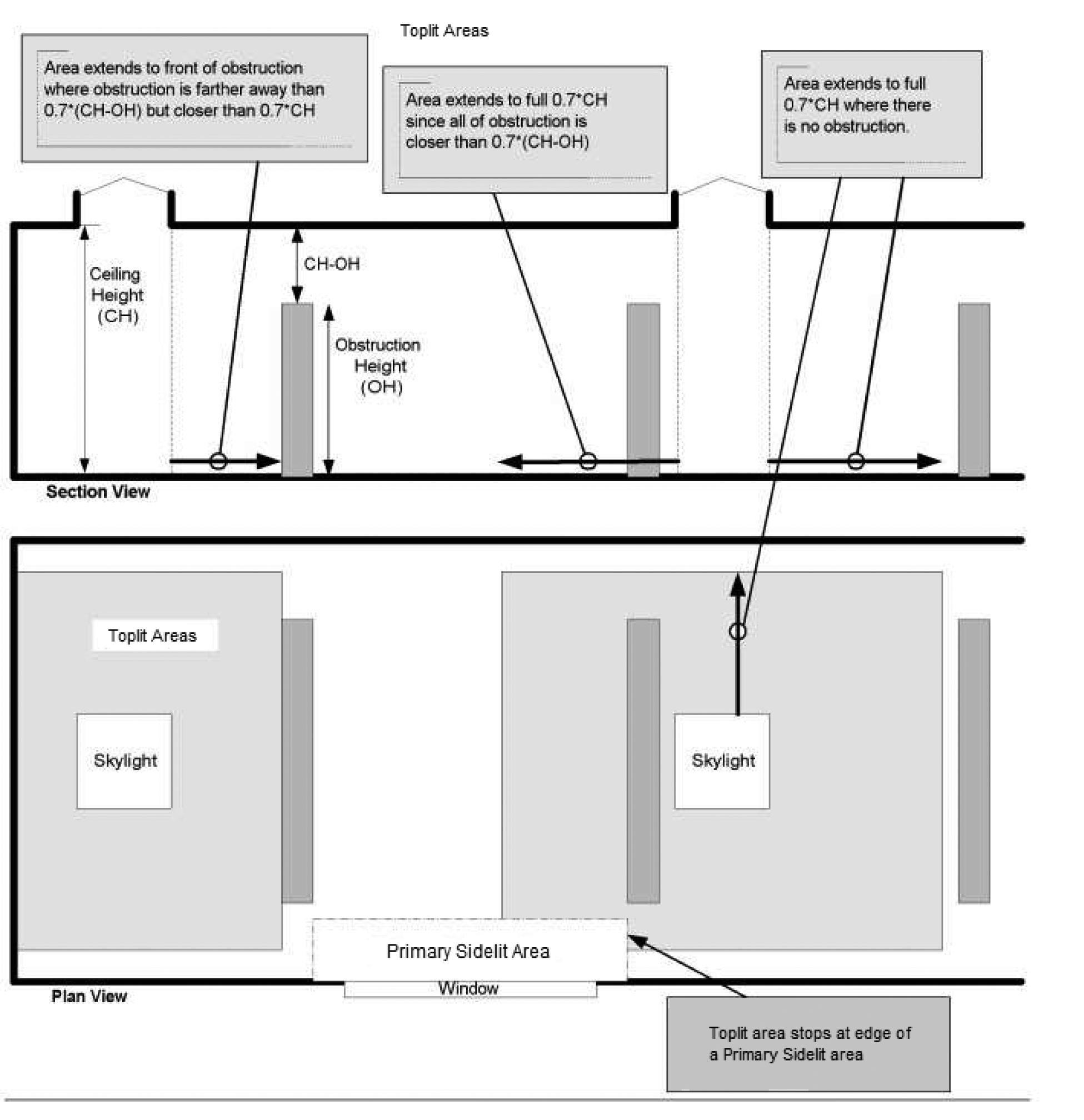
| 1.3. Areas where it is documented that existing structures or natural objects block direct beam sunlight on at least half of the roof over the enclosed area for more than 1,500 daytime hours per year between 8 a.m. and 4 p.m. |
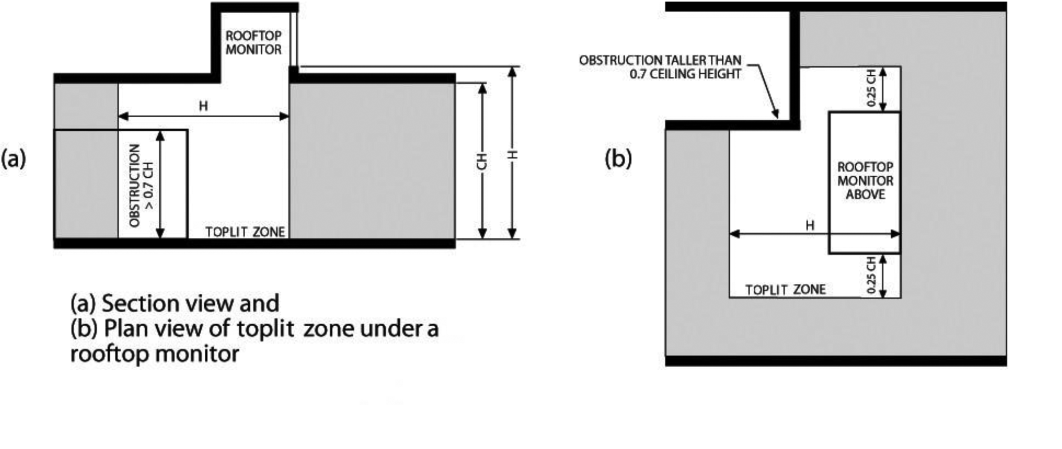
| 1.4. Spaces where the daylight zone under rooftop monitors is greater than 50 percent of the enclosed space floor area. |
| 1.5. Spaces where the total floor area minus the sidelit daylight zone area is less than 2,500 square feet (232 m2), and where the lighting in the daylight zone is controlled in accordance with Section ((C405.2.3.1))C405.2.4.1. |
| 2. The skylight effective aperture, calculated in accordance with Equation 4-5, is permitted to be 0.66 percent in lieu of 1 percent if the VTannual of the skylight or TDD, as measured by NFRC 203, is greater than 38 percent. |
C402.4.2.1 Lighting controls in daylight zones under skylights. Daylight responsive controls shall be provided to control all electric lights within toplit daylight zones.
C402.4.2.2 Haze factor. Skylights in office, storage, automotive service, manufacturing, nonrefrigerated warehouse, retail store, and distribution/sorting area spaces shall have a glazing material or diffuser with a haze factor greater than 90 percent when tested in accordance with ASTM D 1003.
EXCEPTION: | Skylights and tubular daylighting devices designed and installed to exclude direct sunlight entering the occupied space by the use of fixed or automated baffles, or the geometry of skylight and light well. |
C402.4.2.3 Daylight zones. Daylight zones referenced in Sections C402.4.1.1 through C402.4.2.2 shall comply with Sections C405.2.5.2 and C405.2.5.3, as applicable. Daylight zones shall include toplit daylight zones and sidelit daylight zones.
AMENDATORY SECTION(Amending WSR 22-14-091, 23-12-101, and 23-20-021, filed 7/1/22, 6/7/23, and 9/25/23, effective 3/15/24)
WAC 51-11C-40241Section C402.5.1—Air barriers.
C402.5.1 Air barriers. A continuous air barrier shall be provided throughout the building thermal envelope. The continuous air barriers shall be located on the inside or outside of the building thermal envelope, located within the assemblies composing the building thermal envelope, or any combination thereof. The air barrier shall comply with Sections C402.5.1.1 and C402.5.1.2.
C402.5.1.1 Air barrier construction. The continuous air barrier shall be constructed to comply with the following:
1. The air barrier shall be continuous for all assemblies that are the thermal envelope of the building and across the joints and assemblies.
2. Air barrier joints and seams shall be sealed, including sealing transitions in places and changes in materials. The joints and seals shall be securely installed in or on the joint for its entire length so as not to dislodge, loosen or otherwise impair its ability to resist positive and negative pressure from wind, stack effect and mechanical ventilation.
3. Penetrations of the air barrier shall be caulked, gasketed or otherwise sealed in a manner compatible with the construction materials and location. Sealing shall allow for expansion, contraction and mechanical vibration. Joints and seams associated with penetrations shall be sealed in the same manner or taped. Sealing materials shall be securely installed around the penetration so as not to dislodge, loosen or otherwise impair the penetrations' ability to resist positive and negative pressure from wind, stack effect, and mechanical ventilation. Sealing of concealed fire sprinklers, where required, shall be in a manner that is recommended by the manufacturer. Caulking or other adhesive sealants shall not be used to fill voids between fire sprinkler cover plates and walls or ceilings.
4. Recessed lighting fixtures shall comply with Section C402.5.8. Where similar objects are installed which penetrate the air barrier, provisions shall be made to maintain the integrity of the air barrier.
5. Construction documents shall contain a diagram showing the building's pressure boundary in plan(s) and section(s) and a calculation of the area of the pressure boundary to be considered in the test.
C402.5.1.2 Air barrier compliance. A continuous air barrier for the opaque building envelope shall comply with the following:
1. Group R dwelling units that are accessed directly from the outdoors shall meet the provisions of Section C402.5.2.
2. All other buildings or portions of buildings shall meet the provisions of Section C402.5.3.
C402.5.2 Enclosure testing for dwelling and sleeping units accessed directly from the outdoors. For dwelling units accessed directly from outdoors, the building thermal envelope shall be tested in accordance with ASTM E779, ANSI/RESNET/ICC 380, ASTM E1827 or an equivalent method approved by the code official. The measured air leakage shall not exceed 0.25 cfm/ft2 (1.27 L/s m2) of the testing unit enclosure area at a pressure differential of 0.2 inch water gauge (50 Pa). Where multiple dwelling units or sleeping units or other occupiable conditioned spaces are contained within one building thermal envelope and are accessed directly from the outdoors, each unit shall be considered an individual testing unit, and the building air leakage shall be the weighted average of all testing unit results, weighted by each testing unit's enclosure area. Units shall be tested separately with an unguarded blower door test as follows:
1. Where buildings have fewer than eight testing units, each testing unit shall be tested.
2. For buildings with eight or more testing units, the greater of seven units or 20 percent of the testing units in the building shall be tested, including a top floor unit, a ground floor unit and a unit with the largest testing unit enclosure area. For each tested unit that exceeds the maximum air leakage rate, an additional two units shall be tested, including a mixture of testing unit types and locations.
3. Test shall be accomplished using either a) both pressurization and depressurization or b) pressurization alone, but not depressurization alone. The test results shall be plotted against the correct P for pressurization in accordance with Section 9.4 of ASTM E779.
Where the measured air leakage rate exceeds 0.25 cfm/ft2 (2.0 L/s x m2) corrective action shall be taken to seal leaks in the air barrier in all units exceeding the target value and all untested units. Post-corrective action testing and repeated corrective action measures will be taken until the required air leakage rating is achieved. Final passing air leakage test results shall be submitted to the code official.
C402.5.3 Building thermal envelope testing. The building thermal envelope shall be tested in accordance with ASTM E779, ANSI/RESNET/ICC 380, ASTM E3158 or ASTM E1827 or an equivalent method approved by the code official. The measured air leakage shall not exceed 0.25 cfm/ft2 (1.27 L/s × m2) of the building thermal envelope area at a pressure differential of 0.3 inch water gauge (75 Pa). Alternatively, portions of the building shall be tested and the measured air leakages shall be area weighted by the surface areas of the building envelope in each portion. The weighted average test results shall not exceed the whole building leakage limit. In the alternative approach, the following portions of the building shall be tested:
1. The entire envelope area of all stories that have any spaces directly under a roof.
2. The entire envelope area of all stories that have a building entrance, exposed floor, or loading dock, or are below grade.
3. Representative above-grade sections of the building totaling at least 25 percent of the wall area enclosing the remaining conditioned space.
4. Test shall be accomplished using either a) both pressurization and depressurization or b) pressurization alone, but not depressurization alone. The test results shall be plotted against the correct P for pressurization in accordance with Section 9.4 of ASTM E779.
Where the measured air leakage rate exceeds 0.25 cfm/ft2 (2.0 L/s x m2) corrective action shall be taken to seal leaks in the air barrier. Post-corrective action testing and repeated corrective action measures will be taken until the required air leakage rating is achieved. Final passing of the air leakage test results shall be submitted to the code official.
C402.5.4 Building test for mixed-use buildings. Where a building is three or fewer stories above grade plane and contains both commercial and residential uses, the air barrier of the R-2 and R-3 occupancy areas of the building is permitted to be separately tested according to Section R402.4.1.2. Alternatively, it is permissible to test the air barrier of the entire building according to Section C402.5.3, provided that the tested air leakage rate does not exceed the rate specified in Section C402.5.3.
AMENDATORY SECTION(Amending WSR 22-14-091, 23-12-101, and 23-20-021, filed 7/1/22, 6/7/23, and 9/25/23, effective 3/15/24)
WAC 51-11C-40243Section C402.5.5—Rooms containing fuel-burning appliances.
C402.5.5 Rooms containing fuel-burning appliances. Where combustion air is supplied through openings in an exterior wall to a room or space containing a space conditioning fuel-burning appliance, one of the following shall apply:
1. The room or space containing the appliance shall be located outside of the building thermal envelope.
2. The room or space containing the appliance shall be enclosed and isolated from conditioned spaces inside the building thermal envelope. Such rooms shall comply with all of the following:
2.1. The walls, floor and ceiling that separate the enclosed room or space from the conditioned spaces shall be insulated to be at least equivalent to the insulation requirement of below grade walls as specified in Table C402.1.3 or C402.1.4.
2.2. The walls, floors and ceilings that separate the enclosed room or space from conditioned spaces be sealed in accordance with Section C402.5.1.1.
2.3. The doors into the enclosed room or space shall be fully gasketed.
2.4. Water lines and ducts in the enclosed room or space shall be insulated in accordance with Section C403.
2.5. Where the air duct supplying combustion air to the enclosed room or space passes through conditioned space, the duct shall be insulated to an R-value of not less than R-16.
EXCEPTION: | Fireplaces and stoves complying with Sections 901 through 905 of the International Mechanical Code, and Section ((2111.13))2111.14 of the International Building Code. |
AMENDATORY SECTION(Amending WSR 22-14-091, 23-12-101, and 23-20-021, filed 7/1/22, 6/7/23, and 9/25/23, effective 3/15/24)
WAC 51-11C-40320Section C403.2—System design.
C403.2 System design. Mechanical systems shall be designed to comply with Sections C403.2.1 ((and))through C403.2.4. Where elements of a building's mechanical systems are addressed in Sections C403.3 through C403.13, such elements shall comply with the applicable provisions of those sections.
AMENDATORY SECTION(Amending WSR 22-14-091, 23-12-101, and 23-20-021, filed 7/1/22, 6/7/23, and 9/25/23, effective 3/15/24)
WAC 51-11C-40332Section C403.3.2—HVAC equipment performance requirements.
C403.3.2 HVAC equipment performance requirements. Equipment shall meet the minimum efficiency requirements of Tables C403.3.2(1) through C403.3.2(16) when tested and rated in accordance with the applicable test procedure. Plate-type liquid-to-liquid heat exchangers shall meet the minimum requirements of AHRI 400. The efficiency shall be verified through certification and listed under an approved certification program or, if no certification program exists, the equipment efficiency ratings shall be supported by data furnished by the manufacturer. Where multiple rating conditions or performance requirements are provided, the equipment shall satisfy all stated requirements. Where components, such as indoor or outdoor coils, from different manufacturers are used, calculations and supporting data shall be furnished by the designer that demonstrates that the combined efficiency of the specified components meets the requirements herein.
C403.3.2.1 Gas-fired and oil-fired forced air furnaces. Forced air furnaces with input ratings ≥ 225,000 Btu/h (65 kW) and all unit heaters shall also have an intermittent ignition or interrupted device (IID), and have either mechanical draft (including power venting) or a flue damper. A vent damper is an acceptable alternative to a flue damper for furnaces where combustion air is drawn from the conditioned space. All furnaces with input ratings ≥ 225,000 Btu/h (65 kW), including electric furnaces, that are not located within the conditioned space shall have jacket losses not exceeding 0.75 percent of the input rating.
C403.3.2.2 Hydronic and multiple-zone HVAC system controls and equipment. Hydronic and multiple-zone HVAC system controls and equipment shall comply with this section.
For buildings with a total equipment cooling capacity of 300 tons and above, the equipment shall comply with one of the following:
1. No one unit shall have a cooling capacity of more than 2/3 of the total installed cooling equipment capacity;
2. The equipment shall have a variable speed drive; or
3. The equipment shall have multiple compressors.
C403.3.2.3 Chillers. Chilled water plants and buildings with more than 500 tons total capacity shall not have more than 100 tons provided by air-cooled chillers.
EXCEPTIONS: | 1. Where the designer demonstrates that the water quality at the building site fails to meet manufacturer's specifications for the use of water-cooled equipment. |
| 2. Air-cooled chillers with minimum efficiencies at least 10 percent higher than those listed in Table C403.3.2(3). |
| 3. Replacement of existing air-cooled chiller equipment. |
| 4. Air-to-water heat pump units that are configured to provide both heating and cooling and that are rated in accordance with AHRI 550/590. |
C403.3.2.4 Water-cooled centrifugal chilling packages. Equipment not designed for operation at AHRI Standard 550/590 test conditions of 44.00°F (6.67°C) leaving and 54.00°F (12.22°C) entering chilled-water temperatures and with 85.00°F (29.44°C) entering and 94.30°F (34.61°C) leaving condenser-fluid temperatures, shall have maximum full-load kW/ton (FL) and part-load ratings adjusted using the following equations.
(Equation 4-7)
(Equation 4-8)
Where: | |
Kadj | = | A × B |
FL | = | Full-load kW/ton values as specified in Table C403.3.2(7) |
FLadj | = | Maximum full-load kW/ton rating, adjusted for nonstandard conditions |
IPLV.IP | = | Value as specified in Table C403.3.2(7) |
PLVadj | = | Maximum NPLV rating, adjusted for nonstandard conditions |
A | = | 0.00000014592 × (LIFT)4 - 0.0000346496 × (LIFT)3+ 0.00314196 × (LIFT)2 - 0.147199 × LIFT + 3.93073 |
B | = | 0.0015 × LvgEvap (° F) + 0.934 |
LIFT | = | LvgCond - LvgEvap |
LvgCond | = | Full-load condenser leaving fluid temperature (°F) |
LvgEvap | = | Full-load evaporator leaving temperature (°F) |
The FLadj and PLVadj values are applicable only for centrifugal chillers meeting all of the following full-load design ranges:
• 36.00°F ≤ LvgEvap ≤ 60.00°F
• LvgCond ≤ 115.00°F
• 20.00°F ≤ LIFT ≤ 80.00°F
Manufacturers shall calculate the FLadj and ((PLVadjbefore))PLVadj before determining whether to label the chiller. Centrifugal chillers designed to operate outside of these ranges are not covered by this code.
C403.3.2.5 Positive displacement (air- and water-cooled) chilling packages. Equipment with a leaving fluid temperature higher than 32°F (0°C) and water-cooled positive displacement chilling packages with a condenser leaving fluid temperature below 115°F (46°C) shall meet the requirements the tables in Section C403.3.2 when tested or certified with water at standard rating conditions, in accordance with the referenced test procedure.
C403.3.2.6 Packaged and split system electric heating and cooling equipment. Packaged and split system equipment providing both electric heating and cooling, and cooling-only equipment with electric heat in the main supply duct before VAV boxes, in each case with a total cooling capacity greater than 6,000 Btu/h shall be a heat pump configured to operate in heat pump mode whenever the outdoor air temperature is above 25°F (-3.9°C) and the unit is not in defrost. The unit shall have reverse-cycle demand defrost.
EXCEPTION: | Unstaffed equipment shelters or cabinets used solely for personal wireless service facilities. |
C403.3.2.7 Humidification. If an air economizer is required on a cooling system for which humidification equipment is to be provided to maintain minimum indoor humidity levels, then the humidifier shall be of the adiabatic type (direct evaporative media or fog atomization type).
EXCEPTIONS: | 1. Health care facilities licensed by the state where chapter 246-320 or 246-330 WAC requires steam injection humidifiers in duct work downstream of final filters. |
| 2. Systems with water economizer. |
| 3. 100 percent outside air systems with no provisions for air recirculation to the central supply fan. |
| 4. Nonadiabatic humidifiers cumulatively serving no more than 10 percent of a building's air economizer capacity as measured in cfm. This refers to the system cfm serving rooms with stand alone or duct mounted humidifiers. |
AMENDATORY SECTION(Amending WSR 22-14-091, 23-12-101, and 23-20-021, filed 7/1/22, 6/7/23, and 9/25/23, effective 3/15/24)
WAC 51-11C-403323Table C403.3.2(3)—Water chilling packages—Minimum efficiency requirements.
Table C403.3.2(3)
Water Chilling Packages—Minimum Efficiency Requirementsa,b,e,f
| Size Category | | Path A | Path B | Test Procedurec |
Equipment Type | Units | FL | ((IPLV,IP))IPLV.IP | FL | ((IPLV,IP))IPLV.IP |
Air-cooled chillers | < 150 tons | EER(Btu/Wh) | ≥ 10.100 | ≥ 13.700 | ≥ 9.700 | ≥ 15.800 | |
≥ 150 tons | EER(Btu/Wh) | ≥ 10.100 | ≥ 14.000 | ≥ 9.700 | ≥ 16.100 | |
Air cooled without condenser, electrically operated | All capacities | EER(Btu/Wh) | Air-cooled chillers without condensers shall be rated with matching condensers and comply with the air-cooled chiller efficiency requirements | |
Water cooled, electrically operated, positive displacement | < 75 tons | kW/ton | ≤ 0.750 | ≤ 0.600 | ≤ 0.780 | ≤ 0.500 | |
≥ 75 tons and < 150 tons | kW/ton | ≤ 0.720 | ≤ 0.560 | ≤ 0.750 | ≤ 0.490 | AHRI 550/590 |
≥ 150 tons and < 300 tons | kW/ton | ≤ 0.660 | ≤ 0.540 | ≤ 0.680 | ≤ 0.440 | |
≥ 300 tons and < 600 tons | kW/ton | ≤ 0.610 | ≤ 0.520 | ≤ 0.625 | ≤ 0.410 | |
| ≥ 600 tons | kW/ton | ≤ 0.560 | ≤ 0.500 | ≤ 0.585 | ≤ 0.380 | |
Water cooled, electrically operated, centrifugal | < 150 tons | kW/ton | ≤ 0.610 | ≤ 0.550 | ≤ 0.695 | ≤ 0.440 | |
≥ 150 tons and < 300 tons | kW/ton | ≤ 0.610 | ≤ 0.550 | ≤ 0.695 | ≤ 0.400 | |
≥ 300 tons and < 400 tons | kW/ton | ≤ 0.560 | ≤ 0.520 | ≤ 0.595 | ≤ 0.390 | |
≥ 400 tons and < 600 tons | kW/ton | ≤ 0.560 | ≤ 0.500 | ≤ 0.585 | ≤ 0.380 | |
≥ 600 tons | kW/ton | ≤ 0.560 | ≤ 0.500 | ≤ 0.585 | ≤ 0.380 | |
Air cooled absorption, single effect | All capacities | COP(W/W) | ≥ 0.600 | NR | NAd | NAd | |
Water cooled absorption, single effect | All capacities | COP(W/W) | ≥ 0.700 | NR | NAd | NAd | AHRI 560 |
Absorption double effect, indirect fired | All capacities | COP(W/W) | ≥ 1.000 | ≥ 1.050 | NAd | NAd |
Absorption double effect, direct fired | All capacities | COP(W/W) | ≥ 1.000 | ≥ 1.000 | NAd | NAd | |
For SI: 1 ton = 3517 W, 1 British thermal unit per hour = 0.2931 W, °C = [(°F) - 32]/1.8. |
| NR = No requirement. |
| a | Chapter 6 contains a complete specification of the referenced standards, which includes test procedures, including the referenced year version of the test procedure. |
| b | The requirements for centrifugal chiller shall be adjusted for nonstandard rating conditions per Section C403.3.2.4 and are applicable only for the range of conditions listed there. The requirements for air-cooled, water-cooled positive displacement and absorption chillers are at standard rating conditions defined in the referenced test procedure. |
| c | Both the full load and IPLV.IP requirements must be met or exceeded to comply with this standard. When there is a Path B, compliance can be with either Path A or Path B for any application. |
| d | NA means the requirements are not applicable for Path B and only Path A can be used for compliance. |
| e | FL is the full-load performance requirements, and IPLV.IP is for the part-load performance requirements. |
| f | This table is a replica of ASHRAE 90.1 Table 6.8.1-3 Water-Chilling Packages—Minimum Efficiency Requirements. |
AMENDATORY SECTION(Amending WSR 22-14-091, 23-12-101, and 23-20-021, filed 7/1/22, 6/7/23, and 9/25/23, effective 3/15/24)
WAC 51-11C-40334Section C403.3.4—Boilers.
C403.3.4Boiler requirements.Boiler systems shall comply with ((the following:))Sections C403.3.4.1 through C403.3.4.5.2.
C403.3.4.1 Combustion air positive shut-off. Combustion air positive shut-off shall be provided on all newly installed boiler systems as follows:
1. All boiler systems with an input capacity of 2,500,000 Btu/h and above, in which the boiler is designed to operate with a nonpositive vent static pressure.
2. All boiler systems where one stack serves two or more boilers with a total combined input capacity per stack of 2,500,000 Btu/h.
C403.3.4.2 Boiler system oxygen concentration controls. Boiler system combustion air fans with motors 10 horsepower or larger shall meet one of the following for newly installed boilers:
1. The fan motor shall be variable speed; or
2. The fan motor shall include controls that limit the fan motor demand to no more than 30 percent of the total design wattage at 50 percent of design air volume.
C403.3.4.3 Boiler oxygen concentration controls. Newly installed boilers with an input capacity of 5,000,000 Btu/h and greater and a steady state full-load combustion efficiency less than 90 percent shall maintain stack-gas oxygen concentrations not greater than the values specified in Table C403.3.4.3. Combustion air volume shall be controlled with respect to measured flue gas oxygen concentration. The use of a common gas and combustion air control linkage or jack shaft is prohibited.
EXCEPTION: | These concentration limits do not apply where 50 percent or more of the boiler system capacity serves Group R-2 occupancies. |
Table C403.3.4.3
Boiler Stack-Gas Oxygen Concentrations
Boiler System Type | Maximum Stack-Gas Oxygen Concentrationa |
Less than 10% of the boiler system capacity is used for process applications at design conditions | 5% |
All others | 3% |
a | Concentration levels measured by volume on a dry basis over firing rates of 20 to 100 percent. |
C403.3.4.4 Boiler turndown.Boiler systems with design input of greater than 1,000,000 Btu/h (293 kW) shall comply with the turndown ratio specified in Table C403.3.4.4.
The system turndown requirement shall be met through the use of multiple single input boilers, one or more modulating boilers or a combination of single input and modulating boilers.
Table C403.3.4.4
Boiler Turndown
Boiler System Design Input (Btu/h) | Minimum Turndown Ratio |
≥ 1,000,000 and less than or equal to 5,000,000 | 3 to 1 |
≥ 5,000,000 and less than or equal to 10,000,000 | 4 to 1 |
≥ 10,000,000 | 5 to 1 |
C403.3.4.5 Buildings with high-capacity space-heating gas boiler systems. New buildings with gas hot water boiler systems for space heating with a total system input of at least 1,000,000 Btu/h but not more than 10,000,000 Btu/h shall comply with this section.
EXCEPTIONS: | 1. Where 25 percent of the annual space heating requirement is provided by site-recovered energy, or heat recovery chillers. |
| 2. Space heating boilers installed in individual dwelling units. |
| 3. Where 50 percent or more of the design heat load is served using perimeter convective heating, radiant ceiling panels, or both. |
| 4. Individual gas boilers with input capacity less than 300,000 Btu/h shall not be included in the calculations of the total system input or total system efficiency. |
C403.3.4.5.1 Boiler efficiency. Gas hot water boilers shall have a minimum thermal efficiency (Et) of 90 percent when rated in accordance with the test procedures in Table C403.3.2(6). Systems with multiple boilers are allowed to meet this requirement if the space-heating input provided by equipment with thermal efficiency (Et) above and below 90 percent provides an input capacity-weighted average thermal efficiency of at least 90 percent. For boilers rated only for combustion efficiency, the calculation for the input capacity-weighted average thermal efficiency shall use the combustion efficiency value.
C403.3.4.5.2 Hot water distribution system design. The hot water distribution system shall be designed to meet all of the following:
1. Coils and other heat exchangers shall be selected so that at design conditions the hot water return temperature entering the boilers is 120°F (48.9°C) or less.
2. Under all operating conditions, the water temperature entering the boiler is 120°F (48.9°C) or less, or the flow rate of supply hot water that recirculates directly into the return system, such as three-way valves or minimum flow bypass controls, shall be no greater than 20 percent of the design flow of the operating boilers.
AMENDATORY SECTION(Amending WSR 22-14-091, 23-12-101, and 23-20-021, filed 7/1/22, 6/7/23, and 9/25/23, effective 3/15/24)
WAC 51-11C-40335Section C403.3.5—Dedicated outdoor air systems.
C403.3.5 Dedicated outdoor air systems (DOAS). For buildings with occupancies as shown in Table C403.3.5, outdoor air shall be provided to each occupied space by a dedicated outdoor air system (DOAS) which delivers 100 percent outdoor air without requiring operation of the heating and cooling system fans for ventilation air delivery.
EXCEPTIONS: | 1. Occupied spaces that are not ventilated by a mechanical ventilation system and are only ventilated by a natural ventilation system in accordance with Section 402 of the International Mechanical Code. |
| 2. High efficiency variable air volume (VAV) systems complying with Section C403.6.10 for occupancy classifications other than Groups A-1, A-2 and A-3 as specified in Table C403.3.5, and high efficiency VAV systems complying with Section C403.12 for occupancy classification Groups A-1, A-2 and A-3 as specified in Table C403.3.5. This exception shall not be used as a substitution for a DOAS per Section C406.6. |
Table C403.3.5
Occupancy Classifications Requiring DOAS
Occupancy Classificationa | Inclusions | Exempted |
A-1 | All occupancies not specifically exempted | Television and radio studios |
A-2 | Casinos (gaming area) | All other A-2 occupancies |
A-3 | Lecture halls, community halls, exhibition halls, gymnasiums, courtrooms, libraries, places of religious worship | All other A-3 occupancies |
A-4, A-5 | | All occupancies excluded |
B | All occupancies not specifically exempted | Food processing establishments including commercial kitchens, restaurants, cafeterias; laboratories for testing and research; data processing facilities and telephone exchanges; air traffic control towers; animal hospitals, kennels, pounds; ambulatory care facilities |
F, H, I, R, S, U | | All occupancies excluded |
E, M | All occupancies included | |
a. | Occupancy classification from the International Building Code Chapter 3. |
C403.3.5.1 DOAS with energy recovery ventilation. The DOAS shall include energy recovery. The energy recovery ((ventilation system))device shall have a 68 percent minimum sensible recovery effectiveness ((of the energy recovery device)) as calculated in accordance with Equation 4-9 or provide an enthalpy recovery ratio of not less than 60 percent at design conditions in accordance with Section C403.7.6. The airflow rate thresholds in Section C403.7.6 that define when the energy recovery requirements in that section do not apply, are not applicable to this section. The return/exhaust air stream temperature for heat recovery device selection shall be 70°F (21°C) at 30 percent relative humidity, or as calculated by the registered design professional.
(Equation 4-9)
| Sensible Recovery Effectiveness | = | TOA - TSA | |
| TOA - TRA | |
Where: |
| TOA | = | Design outdoor air dry bulb temperature entering the energy recovery device. |
| TSA | = | Supply air dry bulb temperature leaving the energy recovery device at design temperatures and airflow conditions, as selected for the proposed DOAS unit(s). |
| TRA | = | Design return air dry bulb temperature. |
EXCEPTIONS: | 1. Systems installed for the sole purpose of providing makeup air for systems exhausting toxic, flammable, paint, or corrosive fumes or dust, dryer exhaust, or commercial kitchen hoods used for collecting and removing grease vapors and smoke. |
| 2. Heat recovery and energy recovery ventilators (H/ERV) that are rated and listed in accordance with HVI 920 can demonstrate compliance with the sensible recovery effectiveness requirement using the adjusted sensible recovery effectiveness (ASRE) rating of the equipment at 32°F test conditions. Applied flow rate for ASRE rating shall be no less than the design flow rate or the closest value interpolated between two listed flow rates. |
| 3. The energy recovery systems for Group R-2 occupancies are permitted to provide 60 percent minimum sensible heat recovery effectiveness in lieu of 68 percent sensible recovery effectiveness in accordance with Section C403.7.6. The return/exhaust air stream temperature for heat recovery device selection shall be 70°F (21°C) or as determined by an approved calculation procedure. |
C403.3.5.2 DOAS fan power. For a DOAS that does not have at least one fan or fan array with fan electrical input power ≥ 1 kW, the total combined fan power shall not exceed 1 watt per cfm of outdoor air as calculated in accordance with Equation 4-10 using design maximum airflows and external static pressures. For a DOAS with at least one fan or fan array with fan electrical input power ≥ 1 kW, the DOAS shall comply with the fan power limitations of Section C403.8.1. DOAS total combined fan power shall include all supply, exhaust and other fans utilized for the purpose of ventilation. This fan power restriction applies to each DOAS in the permitted project, but does not include the fan power associated with the zonal heating and cooling equipment.
(Equation 4-10)
| DOAS Total Combined Fan Power | | |
Where: |
| Fan bhp | = | Brake horsepower for each supply, exhaust and other fan in the system at design maximum airflow rate. |
| ƞm | = | Fan motor efficiency including all motor, drive and other losses for each fan in the system. |
| CFMsupply | = | Design maximum airflow rate of outdoor (supply) air. |
C403.3.5.3 Heating and cooling system fan controls. Heating and cooling equipment fans, heating and cooling circulation pumps, and terminal unit fans shall cycle off and terminal unit primary cooling air shall be shut off when there is no call for heating or cooling in the zone.
EXCEPTION: | Fans used for heating and cooling using less than 0.12 watts per cfm may operate when space temperatures are within the setpoint deadband (Section C403.4.1.2) to provide destratification and air mixing in the space. |
C403.3.5.4 Decoupled DOAS supply air. The DOAS supply air shall be delivered directly to the occupied space or downstream of the terminal heating and/or cooling coils.
EXCEPTIONS: | 1. Active chilled beam systems. |
| 2. Sensible only cooling terminal units with pressure independent variable airflow regulating devices limiting the DOAS supply air to the greater of latent load or minimum ventilation requirements. |
| 3. Terminal heating and/or cooling units that comply with the low fan power allowance requirements in the exception of Section C403.3.5.3. |
C403.3.5.5 Supplemental heating and cooling. Supply air stream heating in the DOAS system shall comply with Section C403.7.3. Cooling is permitted for dehumidification only. Cooling coil shall be sized to meet peak dehumidification requirement at design outdoor temperatures, and no larger. Cooling coil shall be controlled to maintain supply air relative humidity or zone relative humidity.
EXCEPTION: | Heating permitted for defrost control shall be locked out when outside air temperatures are above 35°F (2°C). Supplemental heating for defrost shall modulate to 10 percent of the peak capacity, and shall be sized to prevent ((frost/damage dame))frost damage to the unit at design temperatures and provide supply air less than or equal to 55°F (13°C). |
C403.3.5.6 Impracticality. Where the code official determines that full compliance with one or more of the requirements in Sections C403.3.5.1 through C403.3.5.5 is impractical, it is permissible to provide an approved alternate means of compliance that achieves a comparable level of energy efficiency as the requirement(s) deemed impractical. For the purposes of this section, impractical means that an HVAC system complying with all requirements in Section C403.3.5 cannot effectively be utilized due to an unusual use or configuration of the building.
AMENDATORY SECTION(Amending WSR 24-03-085, filed 1/16/24, effective 3/15/24)
WAC 51-11C-40341Section C403.4.1—Thermostatic controls.
C403.4.1 Thermostatic controls. The supply of heating and cooling energy to each zone shall be controlled by individual thermostatic controls capable of responding to temperature within the zone. Controls in the same zone or in neighboring zones connected by openings larger than 10 percent of the floor area of either zone shall not allow for simultaneous heating and cooling. At a minimum, each floor of a building shall be considered as a separate zone. Controls on systems required to have economizers and serving single zones shall have multiple cooling stage capability and activate the economizer when appropriate as the first stage of cooling. See Section C403.5 for further economizer requirements. Where humidification or dehumidification or both is provided, at least one humidity control device shall be provided for each humidity control system.
EXCEPTIONS: | 1. Independent perimeter systems that are designed to offset only building envelope heat losses or gains or both serving one or more perimeter zones also served by an interior system provided: |
| 1.1. The perimeter system includes at least one thermostatic control zone for each building exposure having exterior walls facing only one orientation (within +/-45 degrees) (0.8 rad) for more than 50 contiguous feet (15,240 mm); |
| 1.2. The perimeter system heating and cooling supply is controlled by a thermostat located within the zones served by the system; and |
| 1.3. Controls are configured to prevent the perimeter system from operating in a different heating or cooling mode from the other equipment within the zones or from neighboring zones connected by openings larger than 10 percent of the floor area of either zone. |
| 2. Where an interior zone and a perimeter zone are open to each other with permanent openings larger than 10 percent of the floor area of either zone, cooling in the interior zone is permitted to operate at times when the perimeter zone is in heating and the interior zone temperature is at least 5°F (2.8°C) higher than the perimeter zone temperature. For the purposes of this exception, a permanent opening is an opening without doors or other operable closures. |
| 3. Dedicated outdoor air units that provide ventilation air, make-up air or replacement air for exhaust systems are permitted to be controlled based on supply air temperature. The supply air temperature shall be controlled to a maximum of 65°F (18.3°C) in heating and a minimum of 72°F (22°C) in cooling unless the supply air temperature is being reset based on the status of cooling or heating in the zones served or it being reset based on outdoor air temperature. |
C403.4.1.1 Heat pump supplementary heat control. Heat pumps equipped with internal electric resistance heaters shall have controls that prevent supplemental heater operation when the heating load can be met by the heat pump alone during both steady-state operation and setback recovery. Supplemental heater operation is permitted during outdoor coil defrost cycles. Heat pumps equipped with supplemental heaters shall comply with all conditions of Section C403.1.4.
EXCEPTIONS: | 1. Packaged terminal heat pumps (PTHPs) of less than 2 tons (24,000 Btu/hr) cooling capacity and whose ratings meet the requirements shown in Table C403.3.2(4) that have reverse-cycle demand defrost and are configured to operate in heat pump mode whenever the outdoor air temperatures are above 25°F (-3.9°C) and the unit is not in defrost. |
| 2. Heat pumps whose minimum efficiency is regulated by NAECA and whose ratings meet the requirements shown in Table C403.3.2(2) and include all usage of internal electric resistance heating. |
C403.4.1.2 Deadband. Where used to control both heating and cooling, zone thermostatic controls shall be configured to provide a temperature range or deadband of at least 5°F (2.8°C) within which the supply of heating and cooling energy to the zone is shut off or reduced to a minimum.
EXCEPTIONS: | 1. Thermostats requiring manual changeover between heating and cooling modes. |
| 2. Occupancies or applications requiring precision in indoor temperature control as approved by the code official. |
C403.4.1.3 Setpoint overlap restriction. Where a zone has a separate heating and a separate cooling thermostatic control located within the zone, a limit switch, mechanical stop or direct digital control system with software programming shall be configured to prevent the heating setpoint from exceeding the cooling setpoint and to maintain a deadband in accordance with Section C403.4.1.2.
C403.4.1.4 Heated or cooled vestibules and air curtains. The heating system for heated vestibules and air curtains with integral heating shall be provided with controls configured to shut off the source of heating when the outdoor air temperature is greater than 45°F (7°C). Vestibule heating and cooling systems shall be controlled by a thermostat located in the vestibule configured to limit heating to a temperature not greater than 60°F (16°C) and cooling to a temperature not less than 85°F (29°C).
EXCEPTIONS: | 1. Control of heating or cooling provided by transfer air that would otherwise be exhausted. |
| 2. Vestibule heating only systems are permitted to be controlled without an outdoor air temperature lockout when controlled by a thermostat located in the vestibule configured to limit heating to a temperature not greater than 45°F (7°C) where required for freeze protection of piping and sprinkler heads located in the vestibule. |
C403.4.1.5 Hot water boiler outdoor temperature setback control. Hot water boilers that supply heat to the building through one- or two-pipe heating systems shall have an outdoor setback control that lowers the boiler water temperature based on the outdoor temperature.
C403.4.1.6 Operable opening switches for HVAC system thermostatic control. Operable openings meeting the minimum size criteria of Section C402.5.11 and that open to the outdoors from a conditioned space must have controls configured to do the following once doors have been open for 5 minutes:
1. Disable the mechanical heating to the zone or reset the space heating temperature setpoint to 55°F or less within 5 minutes of the door open enable signal.
2. Disable the mechanical cooling to the zone or reset the space cooling temperature setpoint to 85°F or more within 5 minutes of the door open enable signal.
EXCEPTION: | Hydronic radiant heating and cooling systems. |
C403.4.1.7 Demand responsive controls. Thermostatic controls for heating or cooling systems shall be provided with demand responsive controls capable of increasing the cooling setpoint and decreasing the heating setpoint by no less than 4°F (2.2°C). The thermostatic controls shall be capable of performing all other functions provided by the control when the demand responsive controls are not available. Systems with direct digital control of individual zones((report))reporting to a central control panel shall be capable of remotely increasing the cooling setpoint and decreasing the heating setpoint for each zone by no less than 4°F (2.2°C).
EXCEPTION: | Health care and assisted living facilities. |
AMENDATORY SECTION(Amending WSR 22-14-091, 23-12-101, and 23-20-021, filed 7/1/22, 6/7/23, and 9/25/23, effective 3/15/24)
WAC 51-11C-40349Sections C403.4.11 and C403.4.12.
C403.4.11 Direct digital control systems. Direct digital control (DDC) shall be required as specified in Sections C403.4.11.1 through C403.4.11.4.
C403.4.11.1 DDC applications. DDC shall be provided in the applications and qualifications listed in Table C403.4.11.1 and for load management measures where installed to meet the requirements of Section C406.3.
C403.4.11.2 DDC controls. Where DDC is required by Section C403.4.11.1, the DDC system shall be configured to perform all of the following functions, as required to provide the system and zone control logic required in Sections C403.2, C403.5, C403.6.8 and C403.4.3:
1. Monitor zone and system demand for fan pressure, pump pressure, heating and cooling.
2. Transfer zone and system demand information from zones to air distribution system controllers and from air distribution systems to heating and cooling plant controllers.
C403.4.11.3 DDC display. Where DDC is required by Section C403.4.11.1 for new buildings, the DDC system shall be configured to gather and provide trending data and graphically displaying input and output points.
C403.4.11.4 DDC demand response setpoint adjustment. Where DDC is required by Section C403.4.11.1 for new buildings and serve mechanical systems with a cooling capacity exceeding 780,000 Btu/h (2,662 kW), the DDC system shall be capable of demand response setpoint adjustment. The DDC system shall be configured with control logic to increase the cooling zone setpoints by at least 2°F (1°C) and reduce the heating zone setpoints by at least 2°F (1°C) when activated by a demand response signal. The demand response signal shall be a binary input to the control system or other interface approved by the serving electric utility.
Table C403.4.11.1
DDC Applications and Qualifications
Building Status | Application | Qualifications |
New building | Air-handling system and all zones served by the system | Individual systems supplying more than three zones and with fan system bhp of 10 hp and larger |
Chilled-water plant and all coils and terminal units served by the system | Individual plants supplying more than three zones and with design cooling capacity of 300,000 Btu/h and larger |
Hot-water plant and all coils and terminal units served by the system | Individual plants supplying more than three zones and with design heating capacity of 300,000 Btu/h and larger |
Alteration or addition | Zone terminal unit such as VAV box | Where existing zones served by the same air-handling, chilled-water, or hot-water system have DDC |
Air-handling system or fan coil | Where existing air-handling system(s) and fan coil(s) served by the same chilled- or hot-water plant have DDC |
New air-handling system and all new zones served by the system | Individual systems with fan system bhp of 10 hp and larger and supplying more than three zones and more than 75 percent of zones are new |
New or upgraded chilled-water plant | Where all chillers are new and plant design cooling capacity is 300,000 Btu/h and larger |
New or upgraded hot-water plant | Where all boilers are new and plant design heating capacity is 300,000 Btu/h and larger |
C403.4.12 Pressure independent control valves. Where design flow rate of heating water and ((chiller))chilled water coils is 5 gpm or higher, modulating pressure independent control valves shall be provided.
AMENDATORY SECTION(Amending WSR 22-14-091, 23-12-101, and 23-20-021, filed 7/1/22, 6/7/23, and 9/25/23, effective 3/15/24)
WAC 51-11C-40350Section C403.5—Economizers.
C403.5 Economizers. Air economizers shall be provided on all new cooling systems including those serving computer server rooms, electronic equipment, radio equipment, and telephone switchgear. Economizers shall comply with Sections C403.5.1 through C403.5.5.
EXCEPTIONS: | 1a. For other than Group R-2 occupancies, cooling system where the supply fan is not installed outside the building thermal envelope nor in a mechanical room adjacent to outdoors, and is installed in conjunction with DOAS complying with Section C403.3.5 and serving only spaces with year-round cooling loads from lights and equipment of less than 5 watts per square foot. |
| 1b. For Group R-2 occupancies, cooling system where the supply fan is not installed outside the building thermal envelope nor in a mechanical room adjacent to outdoors, and is installed in conjunction with DOAS complying with Section C403.3.5, where the ERV/HRV has a minimum 68 percent sensible recovery or 60 percent enthalpy recovery heating effectiveness (((Exception 3 of Section C403.3.5.1 is not utilized))), and serving only spaces with year-round cooling loads from lights and equipment of less than 5 watts per square foot. |
| 2. Unitary or packaged systems serving one zone with dehumidification that affect other systems so as to increase the overall building energy consumption. New humidification equipment shall comply with Section C403.3.2.7. |
| 3. Unitary or packaged systems serving one zone where the cooling efficiency meets or exceeds the efficiency requirements in Table C403.5. |
| 4. Equipment serving chilled beams and chilled ceiling space cooling systems only which are provided with a water economizer meeting the requirements of Section C403.5.4. |
| 5. For Group R occupancies, cooling unit where the supply fan is not installed outside the building thermal envelope or in a mechanical room adjacent to outdoors with a total cooling capacity less than 20,000 Btu/h and other cooling units with a total cooling capacity less than 54,000 Btu/h provided that these are high-efficiency cooling equipment with IEER, CEER, SEER, and EER values more than 15 percent higher than minimum efficiencies listed in Tables C403.3.2(1), C403.3.2(2), C403.3.2(4), C403.3.2(8) and C403.3.2(9) or an IPLV kW/ton that is at least 15 percent lower than the minimum efficiencies listed in Table C403.3.2(3) or C403.3.2(15), in the appropriate size category, using the same test procedures. Equipment shall be listed in the appropriate certification program to qualify for this exception. For split systems, compliance is based on the cooling capacity of individual fan coil units. |
| 6. Equipment used to cool Controlled Plant Growth Environments provided these are high-efficiency cooling equipment with SEER, EER and IEER values a minimum of 20 percent greater than the values listed in Tables C403.3.2 (1), (3), (4), and (15). |
| 7. Equipment serving a space with year-round cooling loads from lights and equipment of 5 watts per square foot or greater complying with the following criteria: |
| 7.1. Equipment serving the space utilizes chilled water as the cooling source; and |
| 7.2. The chilled water plant includes a condenser heat recovery system that meets the requirements of Section C403.9.5 or the building and water-cooled system meets the following requirements: |
| 7.2.1. A minimum of 90 percent (capacity-weighted) of the building space heat is provided by hydronic heating water. |
| 7.2.2. Chilled water plant includes a heat recovery chiller or water-to-water heat pump capable of rejecting heat from the chilled water system to the hydronic heating equipment capacity. |
| 7.2.3. Heat recovery chillers shall have a minimum COP of 7.0 when providing heating and cooling water simultaneously. |
| 8. Water-cooled equipment served by systems meeting the requirements of Section C403.9.2.4 Condenser heat recovery. |
| 9. Equipment used to cool any dedicated server room, electronic equipment room or telecom switch room provided the system complies with option a, b, or c in the table below. The total cooling capacity of all fan systems without economizers shall not exceed 240,000 Btu/h per building or 10 percent of its air economizer capacity, whichever is greater. This exception shall not be used for total building performance. |
| 10. Dedicated outdoor air systems that include energy recovery as required by Section C403.7.6 but do not include mechanical cooling. |
| 11. Dedicated outdoor air systems not required by Section C403.7.6 to include energy recovery that modulate the supply airflow to provide only the minimum outdoor air required by Section C403.2.2.1 for ventilation, exhaust air make-up, or other process air delivery. |
| Equipment Type | Higher Equipment Efficiency | Part-Load Control | Economizer |
Option a | Tables C403.3.2(1), C403.3.2(2) and C403.3.2 (14)a | +15%b | Required over 85,000 Btu/hc | None Required |
Option b | Tables C403.3.2(1), C403.3.2(2) and C403.3.2 (14)a | +5%d | Required over 85,000 Btu/hc | Waterside Economizere |
Option c | ASHRAE Standard 127f | +0%g | Required over 85,000 Btu/hc | Waterside Economizere |
Notes for Exception 9: |
a | For a system where all of the cooling equipment is subject to the AHRI standards listed in Tables C403.3.2(1), C403.3.2(2), and C403.3.2 (14), the system shall comply with all of the following (note that if the system contains any cooling equipment that exceeds the capacity limits in Table C403.3.2(1), C403.3.2(2), or C403.3.2 (14), or if the system contains any cooling equipment that is not included in Table C403.3.2(1), C403.3.2(2), or C403.3.2 (14), then the system is not allowed to use this option). |
b | The cooling equipment shall have an EER value and an IPLV value that is a minimum of 15 percent greater than the value listed in Tables C403.3.2(1), C403.3.2(2), and C403.3.2 (14). |
c | For units with a total cooling capacity over 85,000 Btu/h, the system shall utilize part-load capacity control schemes that are able to modulate to a part-load capacity of 50 percent of the load or less that results in the compressor operating at the same or higher EER at part loads than at full load (e.g., minimum of two-stages of compressor unloading such as cylinder unloading, two-stage scrolls, dual tandem scrolls, but hot gas bypass is not credited as a compressor unloading system). |
d | The cooling equipment shall have an EER value and an IPLV value that is a minimum of 5 percent greater than the value listed in Tables C403.3.2(1), C403.3.2(2), and C403.3.2 (14). |
e | The system shall include a water economizer in lieu of air economizer. Water economizers shall meet the requirements of C403.5.1 and C403.5.2 and be capable of providing the total concurrent cooling load served by the connected terminal equipment lacking airside economizer, at outside air temperatures of 50°F dry-bulb/45°F wet-bulb and below. For this calculation, all factors including solar and internal load shall be the same as those used for peak load calculations, except for the outside temperatures. The equipment shall be served by a dedicated condenser water system unless a nondedicated condenser water system exists that can provide appropriate water temperatures during hours when waterside economizer cooling is available. |
f | For a system where all cooling equipment is subject to ASHRAE Standard 127. |
g | The cooling equipment subject to the ASHRAE Standard 127 shall have an EER value and an IPLV value that is equal to or greater than the value listed in Tables C403.3.2(1), C403.3.2(2), and C403.3.2 (14) when determined in accordance with the rating conditions ASHRAE Standard 127 (i.e., not the rating conditions in AHRI Standard 210/240 or 340/360). This information shall be provided by an independent third party. |
Table C403.5
Equipment Efficiency Performance
Exception for Economizers
Climate Zones | Efficiency Improvementa |
4C | 64% |
5B | 59% |
a | If a unit is rated with an IPLV, IEER or SEER then to eliminate the required air or water economizer, the minimum cooling efficiency of the HVAC unit must be increased by the percentage shown. If the HVAC unit is only rated with a full load metric like EER or COP cooling, then these must be increased by the percentage shown. |
AMENDATORY SECTION(Amending WSR 22-14-091, 23-12-101, and 23-20-021, filed 7/1/22, 6/7/23, and 9/25/23, effective 3/15/24)
WAC 51-11C-403610Section C403.6.10—High efficiency VAV systems.
C403.6.10 High efficiency variable air volume (VAV) systems. For HVAC systems subject to the requirements of Section C403.3.5 but utilizing Exception 2 of that section, a high efficiency multiple-zone VAV system may be provided without a separate parallel DOAS when the system is designed, installed, and configured to comply with all of the following criteria (this exception shall not be used as a substitution for a DOAS per Section C406.6):
1. Each VAV system must serve a minimum of 3,000 square feet (278.7 m2) and have a minimum of five VAV zones.
2. The VAV systems are provided with airside economizer per Section C403.5 without exceptions.
3. A direct-digital control (DDC) system is provided to control the VAV air handling units and associated terminal units per Section C403.4.11 regardless of sizing thresholds of Table C403.4.11.1.
4. Multiple-zone VAV systems with a minimum outdoor air requirement of 2,500 cfm (1180 L/s) or greater shall be equipped with a device capable of measuring outdoor airflow intake under all load conditions. The system shall be capable of increasing or reducing the outdoor airflow intake based on feedback from the VAV terminal units as required by Section C403.6.5, without exceptions, and Section C403.7.1 demand controlled ventilation.
5. Multiple-zone VAV systems with a minimum outdoor air requirement of 2,500 cfm (1180 L/s) or greater shall be equipped with a device capable of measuring supply airflow to the VAV terminal units under all load conditions.
6. In addition to meeting the zone isolation requirements of C403.2.1 a single VAV air handling unit shall not serve more than 50,000 square feet (4645 m2) unless a single floor is greater than 50,000 square feet (4645 m2) in which case the air handler is permitted to serve the entire floor.
7. The primary maximum cooling air for the VAV terminal units serving interior cooling load driven zones shall be sized for a supply air temperature that is a minimum of 5°F greater than the supply air temperature for the exterior zones in cooling.
8. Air terminal units with a minimum primary airflow setpoint of 50 percent or greater of the maximum primary airflow setpoint shall be sized with an inlet velocity of no greater than 900 feet per minute.
9. ((Allowable fan power))Fan system electrical input power (Fan kWdesign system) shall not exceed 90 percent of the ((allowable)) fan power budget (Fan kWbudget) as defined by Section C403.8.1.1.
10. All fan powered VAV terminal units (series or parallel) shall be provided with electronically commutated motors. The DDC system shall be configured to vary the speed of the motor as a function of the heating and cooling load in the space. Minimum speed shall not be greater than 66 percent of design airflow required for the greater of heating or cooling operation. Minimum speed shall be used during periods of low heating and cooling operation and ventilation-only operation.
EXCEPTION: | For series fan powered terminal units where the volume of primary air required to deliver the ventilation requirements at minimum speed exceeds the air that would be delivered at the speed defined above, the minimum speed setpoint shall be configured to exceed the value required to provide the required ventilation air. |
11. Fan-powered VAV terminal units shall only be permitted at perimeter zones with an envelope heating load requirement. All other VAV terminal units shall be single duct terminal units.
EXCEPTION: | Fan powered VAV terminal units are allowed at interior spaces with an occupant load greater than or equal to 25 people per 1000 square feet of floor area (as established in Table 403.3.1.1 of the International Mechanical Code) with demand control ventilation in accordance with Section C403.7.1. |
12. When in occupied heating or in occupied deadband between heating and cooling all fan powered VAV terminal units shall be configured to reset the primary air supply setpoint, based on the VAV air handling unit outdoor air vent fraction, to the minimum ventilation airflow required per International Mechanical Code.
13. Spaces that are larger than 150 square feet (14 m2) and with an occupant load greater than or equal to 25 people per 1000 square feet (93 m2) of floor area (as established in Table 403.3.1.1 of the International Mechanical Code) shall be provided with all of the following features:
13.1. A dedicated VAV terminal unit capable of controlling the space temperature and minimum ventilation shall be provided.
13.2. Demand control ventilation (DCV) shall be provided that utilizes a carbon dioxide sensor to reset the ventilation setpoint of the VAV terminal unit from the design minimum to design maximum ventilation rate as required by Chapter 4 of the International Mechanical Code.
13.3. Occupancy sensors shall be provided that are configured to reduce the minimum ventilation rate to zero and setback room temperature setpoints by a minimum of 5°F, for both cooling and heating, when the space is unoccupied.
14. Dedicated data centers, computer rooms, electronic equipment rooms, telecom rooms, or other similar spaces with cooling loads greater than 5 watts/sf shall be provided with separate cooling systems to allow the VAV air handlers to turn off during unoccupied hours in the office space and to allow the supply air temperature reset to occur.
EXCEPTION: | The VAV air handling unit and VAV terminal units may be used for secondary backup cooling when there is a failure of the primary HVAC system. |
Additionally, computer rooms, electronic equipment rooms, telecom rooms, or other similar spaces shall be provided with airside economizer in accordance with Section 403.5 without using the exceptions to Section C403.5.
EXCEPTION: | Heat recovery per Exception 9 of Section C403.5 may be in lieu of airside economizer for the separate, independent HVAC system. |
15. HVAC system central heating or cooling plant will include a minimum of one of the following options:
15.1. VAV terminal units with hydronic heating coils connected to systems with hot water generation equipment limited to the following types of equipment: Gas-fired hydronic boilers with a thermal efficiency, Et, of not less than 92 percent, air-to-water heat pumps or heat recovery chillers. Hydronic heating coils shall be sized for a maximum entering hot water temperature of 120°F (48.9°C) for peak anticipated heating load conditions.
15.2. Chilled water VAV air handing units connected to systems with chilled water generation equipment with IPLV values more than 25 percent higher than the minimum part load efficiencies listed in Table C403.3.2(3), in the appropriate size category, using the same test procedures. Equipment shall be listed in the appropriate certification program to qualify. The smallest chiller or compressor in the central plant shall not exceed 20 percent of the total central plant cooling capacity or the chilled water system shall include thermal storage sized for a minimum of 20 percent of the total central cooling plant capacity.
16. The DDC system shall include a fault detection and diagnostics (FDD) system complying with the following:
16.1. The following temperature sensors shall be permanently installed to monitor system operation:
16.1.1. Outside air.
16.1.2. Supply air.
16.1.3. Return air.
16.2. Temperature sensors shall have an accuracy of ±2°F (1.1°C) over the range of 40°F to 80°F (4°C to 26.7°C).
16.3. The VAV air handling unit controller shall be configured to provide system status by indicating the following:
16.3.1. Free cooling available.
16.3.2. Economizer enabled.
16.3.3. Compressor enabled.
16.3.4. Heating enabled.
16.3.5. Mixed air low limit cycle active.
16.3.6. The current value of each sensor.
16.4. The VAV air handling unit controller shall be capable of manually initiating each operating mode so that the operation of compressors, economizers, fans and the heating system can be independently tested and verified.
16.5. The VAV air handling unit shall be configured to report faults to a fault management application able to be accessed by day-to-day operating or service personnel or annunciated locally on zone thermostats.
16.6. The VAV terminal unit shall be configured to report if the VAV inlet valve has failed by performing the following diagnostic check at a maximum interval of once a month:
16.6.1. Command VAV terminal unit primary air inlet valve closed and verify that primary airflow goes to zero.
16.6.2. Command VAV terminal unit primary air inlet valve to design airflow and verify that unit is controlling to within 10 percent of design airflow.
16.7. The VAV terminal unit shall be configured to report and trend when the zone is driving the following VAV air handling unit reset sequences. The building operator shall have the capability to exclude zones used in the reset sequences from the DDC control system graphical user interface:
16.7.1. Supply air temperature setpoint reset to lowest supply air temperature setpoint for cooling operation.
16.7.2. Supply air duct static pressure setpoint reset for the highest duct static pressure setpoint allowable.
16.8. The FDD system shall be configured to detect the following faults:
16.8.1. Air temperature sensor failure/fault.
16.8.2. Not economizing when the unit should be economizing.
16.8.3. Economizing when the unit should not be economizing.
16.8.4. Outdoor air or return air damper not modulating.
16.8.5. Excess outdoor air.
16.8.6. VAV terminal unit primary air valve failure.
AMENDATORY SECTION(Amending WSR 22-14-091, 23-12-101, and 23-20-021, filed 7/1/22, 6/7/23, and 9/25/23, effective 3/15/24)
WAC 51-11C-40376Section C403.7.6—Energy recovery ventilation systems.
C403.7.6 Energy recovery ventilation systems. Energy recovery ventilation systems shall be provided as specified in Sections C403.7.6.1 and C403.7.6.2.
C403.7.6.1 Ventilation for Group R-2 occupancy. For all Group R-2 dwelling and sleeping units, a balanced ventilation system with heat recovery system with minimum 60 percent sensible recovery effectiveness shall provide outdoor air directly to each habitable space in accordance with the International Mechanical Code. The ventilation system shall allow for the design flow rates to be tested and verified at each habitable space as part of the commissioning process in accordance with Section C408.2.2. The return/exhaust air stream temperature for heat recovery device selection shall be 70°F (21°C), or as calculated by the registered design professional.
EXCEPTION: | Heat recovery and energy recovery ventilators (H/ERV) that are rated and listed in accordance with HVI 920 can demonstrate compliance with the sensible recovery effectiveness requirement using the adjusted sensible recovery effectiveness (ASRE) rating of the equipment at 32°F test conditions. Applied flow rate for ASRE rating shall be no less than the design flow rate or the closest value interpolated between two listed flow rates. |
C403.7.6.2 Spaces other than Group R-2 dwelling units. Any system serving a space other than a Group R-2 dwelling or sleeping unit with minimum outside air requirements at design conditions greater than 5,000 cfm or any system where the system's supply airflow rate exceeds the value listed in Tables C403.7.6(1) and C403.7.6(2), based on the climate zone and percentage of outdoor airflow rate at design conditions, shall include an energy recovery system. Table C403.7.6(1) shall be used for all ventilation systems that operate less than 8,000 hours per year, and Table C403.7.6(2) shall be used for all ventilation systems that operate 8,000 hours or more per year. The energy recovery system shall provide a 68 percent minimum sensible recovery effectiveness or have an enthalpy recovery ratio of not less than 60 percent at design conditions. Where an air economizer is required, the energy recovery system shall include a bypass of the energy recovery media for both the outdoor air and exhaust air or return air dampers and controls which permit operation of the air economizer as required by Section C403.5. Where a single room or space is supplied by multiple units, the aggregate ventilation (cfm) of those units shall be used in applying this requirement. The return/exhaust air stream temperature for heat recovery device selection shall be 70°F (21°C) at 30 percent relative humidity, or as calculated by the registered design professional.
EXCEPTION: | An energy recovery ventilation system shall not be required in any of the following conditions: |
| 1. Where energy recovery systems are restricted per Section 514 of the International Mechanical Code to sensible energy, recovery shall comply with one of the following: |
| 1.1. Kitchen exhaust systems where they comply with Section C403.7.7.1. |
| 1.2. Laboratory fume hood systems where they comply with Exception 2 of Section C403.7.6. |
| 1.3. Other sensible energy recovery systems with the capability to provide a change in dry-bulb temperature of the outdoor air supply of not less than 50 percent of the difference between the outdoor air and the return air dry-bulb temperatures, at design conditions. |
| 2. Laboratory fume hood systems that include at least one of the following features and also comply with Section C403.7.7.2: |
| 2.1. Variable-air-volume hood exhaust and room supply systems configured to reduce exhaust and makeup air volume to 50 percent or less of design values. |
| 2.2. Direct makeup (auxiliary) air supply equal to at least 75 percent of the exhaust rate, heated no warmer than 2°F (1.1°C) above room setpoint, cooled to no cooler than 3°F (1.7°C) below room setpoint, no humidification added, and no simultaneous heating and cooling used for dehumidification control. |
| 3. Systems serving spaces that are heated to less than 60°F (15.5°C) and are not cooled. |
| 4. Where more than 60 percent of the outdoor air heating energy is provided from site-recovered energy. |
| 5. Systems exhausting toxic, flammable, paint or corrosive fumes or dust. |
| 6. Cooling energy recovery. |
| 7. Systems requiring dehumidification that employ energy recovery in series with the cooling coil. |
| 8. Multiple-zone systems where the supply airflow rate is less than the values specified in Tables C403.7.6 (1) and (2), for the corresponding percent of outdoor air. Where a value of NR is listed, energy recovery shall not be required. |
| 9. Equipment which meets the requirements of Section C403.9.2.4. |
| 10. Systems serving Group R-1 dwelling or sleeping units where the largest source of air exhausted at a single location at the building exterior is less than 25 percent of the design outdoor air flow rate. |
Table C403.7.6(1)
Energy Recovery Requirement
(Ventilation systems operating less than 8,000 hours per year)
Percent (%) Outdoor Air at Full Design Airflow Rate |
Climate zone | ≥ 10% and < 20% | ≥ 20% and < 30% | ≥ 30% and < 40% | ≥ 40% and < 50% | ≥ 50% and < 60% | ≥ 60% and < 70% | ≥ 70% and < 80% | ≥ 80% |
Design Supply Fan Airflow Rate (cfm) |
4C, 5B | NR | NR | NR | NR | NR | NR | ≥ 5000 | ≥ 5000 |
NR = Not required. |
Table C403.7.6(2)
Energy Recovery Requirement
(Ventilation systems operating not less than 8,000 hours per year)
Percent (%) Outdoor Air at Full Design Airflow Rate |
Climate zone | ≥ 10% and < 20% | ≥ 20% and < 30% | ≥ 30% and < 40% | ≥ 40% and < 50% | ≥ 50% and < 60% | ≥ 60% and < 70% | ≥ 70% and < 80% | ≥ 80% |
Design Supply Fan Airflow Rate (cfm) |
4C | NR | ≥ 19500 | ≥ 9000 | ≥ 5000 | ≥ 4000 | ≥ 3000 | ≥ 1500 | ≥ 120 |
5B | ≥ 2500 | ≥ 2000 | ≥ 1000 | ≥ 500 | ≥ 140 | ≥ 120 | ≥ 100 | ≥ 80 |
NR = Not required. |
AMENDATORY SECTION(Amending WSR 22-14-091, 23-12-101, and 23-20-021, filed 7/1/22, 6/7/23, and 9/25/23, effective 3/15/24)
WAC 51-11C-4038Section C403.8—Fan and fan controls.
C403.8 Fan and fan controls. Fans in HVAC systems shall comply with Sections C403.8.1 through C403.8.5.1.
The airflow requirements of Section C403.8.5.1 shall apply to all fan motors. Low capacity ventilation fans shall also comply with Section C403.8.4.
C403.8.1 Fan System. Each fan system that includes at least one fan or fan array with fan electrical input power ≥ 1 kW, moving air into, out of, or between conditioned spaces or circulating air for the purpose of conditioning air within a space shall comply with Sections C403.8.1.1 through C403.8.1.2.
C403.8.1.1 Determining fan power budget. For each fan system, the fan system electrical input power (Fan kWdesign,system) determined in accordance with Section C403.8.1.2 at the fan system airflow shall not exceed Fan kWbudget. Calculate fan power budget (Fan kWbudget) for each fan system as follows:
1. Determine the fan system airflow and choose the appropriate table(s) for fan power allowance.
1.1. For single-cabinet fan systems, use the fan system airflow and the power allowances in both Table C403.8.1.1(1) and Table C403.8.1.1(2).
1.2. For supply-only fan systems, use the fan system airflow and power allowances in Table C403.8.1.1(1).
1.3. For relief fan systems, use the design relief airflow and the power allowances in Table C403.8.1.1(2).
1.4. For exhaust, return and transfer fan systems, use the fan system airflow and the power allowances in Table C403.8.1.1(2).
1.5. For complex and DOAS with energy recovery fan systems, separately calculate the fan power allowance for the supply and return/exhaust systems and sum them. For the supply airflow, use supply airflow at the fan system design conditions, and the power allowances in Table C403.8.1.1(1). For the return/exhaust airflow, use return/exhaust airflow at the fan system design conditions, and the power allowances in Table C403.8.1.1(2).
2. For each fan system, determine the components included in the fan system and sum the fan power allowances of those components. All fan systems shall include the system base allowance. If, for a given component, only a portion of the fan system airflow passes through the component, calculate the fan power allowance for that component in accordance with Equation 4-11:
(Equation 4-11)
FPAadj | = | (Qcomp/Qsys) × FPAcomp |
Where: |
| FPAadj | = | The corrected fan power allowance for the component in W/cfm. |
| Qcomp | = | The airflow through component in cfm. |
| Qsys | = | The fan system airflow in cfm. |
| FPAcomp | = | The fan power allowance of the component from Table C403.8.1.1(1) or Table C403.8.1.1(2). |
3. Multiply the fan system airflow by the sum of the fan power allowances for the fan system.
4. Divide by 1,000 to convert to Fan kWbudget.
5. For building sites at elevations greater than 3,000 feet, multiply Fan kWbudget by 0.896.
Table C403.8.1.1(1)
Supply Fan Power Allowances (W/CFM)
Airflow | Multi-Zone VAV Systemsa ≤ 5,000 cfm | Multi-Zone VAV Systemsa ˃ 5,000 and ≤ 10,000 cfm | Multi-Zone VAV Systemsa ˃ 10,000 cfm | All Other Fan Systems ≤ 5,000 cfm | All Other Fan Systems ˃ 5,000 and ≤ 10,000 cfm | All Other Fan Systems ˃ 10,000 cfm |
Supply system base allowance for AHU serving spaces ≤ 6 floors away | 0.395 | 0.453 | 0.413 | 0.232 | 0.256 | 0.236 |
Supply system base allowance for AHU serving spaces ˃ 6 floors away | 0.508 | 0.548 | 0.501 | 0.349 | 0.356 | 0.325 |
MERV 13 to MERV 16 Filter upstream of thermal conditioning equipment (two-times the clean filter pressure drop)b | 0.136 | 0.114 | 0.105 | 0.139 | 0.120 | 0.107 |
MERV 13 to MERV 16 Final filter downstream of thermal conditioning equipment (two-times the clean filter pressure drop)b | 0.225 | 0.188 | 0.176 | 0.231 | 0.197 | 0.177 |
Filtration allowance for ˃ MERV 16 or HEPA Filter (two-times the clean filter pressure drop)b | 0.335 | 0.280 | 0.265 | 0.342 | 0.292 | 0.264 |
Central hydronic heating coil allowance | 0.046 | 0.048 | 0.052 | 0.046 | 0.050 | 0.054 |
Electric heat allowance | 0.046 | 0.038 | 0.035 | 0.046 | 0.040 | 0.036 |
Gas heat allowance | 0.069 | 0.057 | 0.070 | 0.058 | 0.060 | 0.072 |
Hydronic/DX cooling coil or heat pump coil (wet) allowancec | 0.135 | 0.114 | 0.105 | 0.139 | 0.120 | 0.107 |
Solid or liquid desiccant system allowance | 0.157 | 0.132 | 0.123 | 0.163 | 0.139 | 0.124 |
Reheat coil for dehumidification allowance | 0.045 | 0.038 | 0.035 | 0.046 | 0.040 | 0.036 |
Allowance for evaporative humidifier/cooler in series with a cooling coil. Value shown is allowed W/cfm per 1.0 inches of water gauge (in.w.g.). Determine pressure loss (in.w.g.) at 400 fpm or maximum velocity allowed by the manufacturer, whichever is lessd | 0.224 | 0.188 | 0.176 | 0.231 | 0.197 | 0.177 |
Allowance for 100% Outdoor air systeme | 0.000 | 0.000 | 0.000 | 0.070 | 0.100 | 0.107 |
Energy recovery allowance for 0.50 ≤ ERR <0.55f | 0.135 | 0.114 | 0.105 | 0.139 | 0.120 | 0.107 |
Energy recovery allowance for 0.55 ≤ ERR <0.60f | 0.160 | 0.134 | 0.124 | 0.165 | 0.141 | 0.126 |
Energy recovery allowance for 0.60 ≤ ERR <0.65f | 0.184 | 0.155 | 0.144 | 0.190 | 0.163 | 0.146 |
Energy recovery allowance for 0.65 ≤ ERR <0.70f | 0.208 | 0.175 | 0.163 | 0.215 | 0.184 | 0.165 |
Energy recovery allowance for 0.70 ≤ ERR <0.75f | 0.232 | 0.196 | 0.183 | 0.240 | 0.205 | 0.184 |
Energy recovery allowance for 0.75 ≤ ERR <0.80f | 0.257 | 0.216 | 0.202 | 0.264 | 0.226 | 0.203 |
Energy recovery allowance for ERR ≥ 0.80f | 0.281 | 0.236 | 0.222 | 0.289 | 0.247 | 0.222 |
Coil runaround loop | 0.135 | 0.114 | 0.105 | 0.139 | 0.120 | 0.107 |
Allowance for Gas phase filtration required by code or accredited standard. Value shown is allowed W/cfm per 1.0 in. wg air pressure dropd | 0.224 | 0.188 | 0.176 | 0.231 | 0.197 | 0.177 |
Economizer damper return | 0.045 | 0.038 | 0.035 | 0.046 | 0.040 | 0.036 |
Air blender allowance | 0.045 | 0.038 | 0.035 | 0.046 | 0.040 | 0.036 |
Sound attenuation section [fans serving spaces with design background noise goals below NC35] | 0.034 | 0.029 | 0.026 | 0.035 | 0.030 | 0.027 |
Deduction for systems that feed a terminal unit with a fan with electrical input power < 1kW | -0.100 | -0.100 | -0.100 | -0.100 | -0.100 | -0.100 |
Low-turndown single-zone VAV fan systemsg | 0.000 | 0.000 | 0.000 | 0.070 | 0.100 | 0.089 |
a | See definition of FAN SYSTEM, MULTI-ZONE VARIABLE AIR VOLUME (VAV). |
b | Filter fan power allowance can only be counted once per fan system, except fan systems in health care facilities, which can claim one of the MERV 13 to 16 filter allowances and the HEPA filter allowance if both are included in the fan system. |
c | Health care facilities can claim this fan power allowance twice per fan system where coil design leaving air temperature is less than 44⁰F. |
d | Power allowance requires further calculation by multiplying the actual inches of water gauge (in.w.g.) of the device/component by the w/cfm in Table C403.8.1(1). |
e | The 100% outdoor air system must serve 3 or more HVAC zones and airflow during noneconomizer operating periods must comply with Section C403.2.2.1. |
f | Enthalpy Recovery Ratio (ERR) calculated per ANSI/ASHRAE 84-2020. |
g | A low-turndown single-zone VAV fan system must be capable of and configured to reduce airflow to 50 percent of design airflow and use no more than 30 percent of the design wattage at that airflow. No more than 10 percent of the design load served by the equipment shall have fixed loads. |
Table C403.8.1.1(2)
Exhaust, Return, Relief, Transfer Fan Power Allowances (W/CFM)
Airflow | Multi-Zone VAV Systemsa ≤ 5,000 cfm | Multi-Zone VAV Systemsa ˃ 5,000 and ≤ 10,000 cfm | Multi-Zone VAV Systemsa ˃ 10,000 cfm | All Other Fan Systems ≤ 5,000 cfm | All Other Fan Systems ˃ 5,000 and ≤ 10,000 cfm | All Other Fan Systems ˃ 10,000 cfm |
Exhaust system base allowance | 0.221 | 0.246 | 0.236 | 0.186 | 0.184 | 0.190 |
Filter (any MERV value)b | 0.046 | 0.041 | 0.036 | 0.046 | 0.041 | 0.035 |
Energy recovery allowance for 0.50 ≤ ERR <0.55c | 0.139 | 0.120 | 0.107 | 0.139 | 0.123 | 0.109 |
Energy recovery allowance for 0.55 ≤ ERR <0.60c | 0.165 | 0.142 | 0.126 | 0.165 | 0.144 | 0.128 |
Energy recovery allowance for 0.60 ≤ ERR <0.65c | 0.190 | 0.163 | 0.146 | 0.191 | 0.166 | 0.148 |
Energy recovery allowance for 0.65 ≤ ERR <0.70c | 0.215 | 0.184 | 0.165 | 0.216 | 0.188 | 0.167 |
Energy recovery allowance for 0.70 ≤ ERR <0.75c | 0.240 | 0.206 | 0.184 | 0.241 | 0.209 | 0.186 |
Energy recovery allowance for 0.75 ≤ ERR <0.80c | 0.265 | 0.227 | 0.203 | 0.266 | 0.231 | 0.205 |
Energy recovery allowance for ERR ≥ 0.80c | 0.289 | 0.248 | 0.222 | 0.291 | 0.252 | 0.225 |
Coil runaround loop | 0.139 | 0.120 | 0.107 | 0.139 | 0.123 | 0.109 |
Return or exhaust systems required by code or accreditation standards to be fully ducted, or systems required to maintain air pressure differentials between adjacent rooms | 0.116 | 0.100 | 0.089 | 0.116 | 0.102 | 0.091 |
Return and/or exhaust airflow control devices | 0.116 | 0.100 | 0.089 | 0.116 | 0.102 | 0.091 |
Laboratory and vivarium exhaust systems in high-rise buildings for vertical duct exceeding 75 ft. Value shown is allowed W/cfm per 0.25 in. wg for each 100 feet exceeding 75 feetd | 0.058 | 0.051 | 0.045 | 0.058 | 0.052 | 0.046 |
Biosafety cabinet. Value shown is allowed W/cfm per 1.0 in. wg air pressure dropd | 0.231 | 0.198 | 0.177 | 0.232 | 0.202 | 0.179 |
Exhaust filters, scrubbers, or other exhaust treatment required by code or standard. Value shown is allowed W/cfm per 1.0 in. wg air pressure dropd | 0.231 | 0.198 | 0.177 | 0.232 | 0.202 | 0.179 |
Health care facility allowancee | 0.231 | 0.198 | 0.177 | 0.232 | 0.202 | 0.179 |
Sound attenuation section [Fans serving spaces with design background noise goals below NC35.] | 0.035 | 0.030 | 0.027 | 0.035 | 0.031 | 0.028 |
a | See definition of FAN SYSTEM, MULTI-ZONE VARIABLE AIR VOLUME (VAV) to be classified as a Multi-Zone VAV System. |
b | Filter pressure loss can only be counted once per fan system. |
c | Enthalpy Recovery Ratio (ERR) calculated per ANSI/ASHRAE 84-2020. |
d | Power allowance requires further calculation, multiplying the actual pressure drop (in. wg) of the device/component by the W/cfm in the Table C403.8.1(2). |
e | This allowance can only be taken for health care facilities. |
C403.8.1.2 Determining Fan System Electrical Input Power (Fan kWdesign,system).Fan kWdesign,system is the sum of Fan kWdesign for each fan or fan array included in the fan system. If variable speed drives are used, their efficiency losses shall be included. Fan input power shall be calculated with two-times the clean filter pressure drop. The Fan kWdesign for each fan or fan array shall be determined using one of the following methods. There is no requirement to use the same method for all fans in a fan system:
1. Use the default Fan kWdesign in Table C403.8.1.2 for one or more of the fans. This method cannot be used for complex fan systems.
2. Use the Fan kWdesign at fan system design conditions provided by the manufacturer of the fan, fan array, or equipment that includes the fan or fan array calculated per a test procedure included in 10 C.F.R. Part 430, 10 C.F.R. Part 431, ANSI/AMCA 208, ANSI/AMCA S210, AHRI 430, AHRI 440, or ISO 5801.
3. Use the Fan kWdesign provided by the manufacturer, calculated at fan system design conditions per one of the methods listed in Section 5.3 of ANSI/AMCA 208.
4. Determine the Fan kWdesign by using the maximum electrical input power provided on the motor nameplate.
Table C403.8.1.2
Default Values for Fan kWdesign Based on Motor Nameplate HPa,b
Motor Nameplate HP | Default Fan kWdesign with variable speed drive (Fan kWdesign) | Default Fan kWdesign without variable speed drive (Fan kWdesign) |
<1 | 0.96 | 0.89 |
≥1 and <1.5 | 1.38 | 1.29 |
≥1.5 and <2 | 1.84 | 1.72 |
≥2 and <3 | 2.73 | 2.57 |
≥3 and <5 | 4.38 | 4.17 |
≥5 and <7.5 | 6.43 | 6.15 |
≥7.5 and <10 | 8.46 | 8.13 |
≥10 and <15 | 12.4 | 12.0 |
≥15 and <20 | 16.5 | 16.0 |
≥20 and <25 | 20.5 | 19.9 |
≥25 and <30 | 24.5 | 23.7 |
≥30 and <40 | 32.7 | 31.7 |
≥40 and <50 | 40.7 | 39.4 |
≥50 and <60 | 48.5 | 47.1 |
≥60 and <75 | 60.4 | 58.8 |
≥75 and ≤100 | 80.4 | 78.1 |
a | This table cannot be used for motor nameplate horsepower values greater than 100. |
b | This table is to be used only with motors with a service factor ≤1.15. If the service factor is not provided, this table may not be used. |
C403.8.2 Motor nameplate horsepower. For each fan, the selected fan motor shall be no larger than the first available motor size greater than the brake horsepower (bhp). The fan brake horsepower (bhp) shall be indicated on the design documents to allow for compliance verification by the code official.
EXCEPTIONS: | 1. For fans less than 6 bhp (4476 W), where the first available motor larger than the brake horsepower has a nameplate rating within 50 percent of the bhp, selection of the next larger nameplate motor size is allowed. |
| 2. For fans 6 bhp (4476 W) and larger, where the first available motor larger than the bhp has a nameplate rating within 30 percent of the bhp, selection of the next larger nameplate motor size is allowed. |
| 3. For fans used only in approved life safety applications such as smoke evacuation. |
| 4. Fans with motor nameplate horsepower less than 1 hp or fans with a fan motor nameplate electrical input power of less than 0.89 kW. |
| 5. Fans equipped with electronic speed control devices to vary the fan airflow as a function of load. |
C403.8.3 Fan efficiency. Each fan and fan array shall have a fan energy index (FEI) of not less than 1.00 at the design point of operation, as determined in accordance with AMCA 208 by an approved, independent testing laboratory and labeled by the manufacturer. Each fan and fan array used for a variable-air volume system shall have an FEI of not less than 0.95 at the design point of operation as determined in accordance with AMCA 208 by an approved, independent testing laboratory and labeled by the manufacturer. The FEI for fan arrays shall be calculated in accordance with AMCA 208 Annex C.
EXCEPTION: | The following fans are not required to have a fan energy index: |
| 1. Fans that are not embedded ((pans))fans with motor nameplate horsepower of less than 1.0 hp (0.75 kW) or with a nameplate electrical input power of less than 0.89 kW. |
| 2. Embedded fans that have a motor nameplate horsepower of 5 hp (3.7 kW) or less or with a fan system electrical input power of 4.1 kW or less. |
| 3. Multiple fans operated in series or parallel as the functional equivalent of a single fan that have a combined motor nameplate horsepower of 5 hp (3.7 kW) or less or with a fan system electrical input power of 4.1 kW or less. |
| 4. Fans that are part of equipment covered under Section C403.3.2. |
| 5. Fans included in an equipment package certified by an approved agency for air or energy performance. |
| 6. Ceiling fans. |
| 7. Fans used for moving gases at temperatures above ((425))482°F (250°C). |
| 8. Fans used for operation in explosive atmospheres. |
| 9. Reversible fans used for tunnel ventilation. |
| 10. Fans that are intended to operate only during emergency conditions. |
| 11. Fans outside the scope of AMCA 208. |
C403.8.4Low-capacity ventilation fans. Mechanical ventilation system fans with motors less than 1/12 hp (0.062 kW) in capacity shall meet the efficacy requirements of Table C403.8.4 at one or more rating points.
EXCEPTIONS: | 1. Where ventilation fans are a component of a listed heating or cooling appliance. |
| 2. Dryer exhaust duct power ventilators and domestic range booster fans that operate intermittently. |
Table C403.8.4
Low-Capacity Ventilation Fan Efficacya
Fan Location | Airflow Rate Minimum (cfm) | Minimum Efficacy (cfm/watt) | Airflow Rate Maximum (cfm) |
HRV or ERV | Any | 1.2 cfm/watt | Any |
Range hood | Any | 2.8 cfm/watt | Any |
In-line fan | Any | 3.8 cfm/watt | Any |
Bathroom, utility room | 10 | 2.8 cfm/watt | < 90 |
Bathroom, utility room | 90 | 3.5 cfm/watt | Any |
For SI: 1 cfm/ft = 47.82 W. |
a | Airflow shall be tested in accordance with HVI 916 and listed. Efficacy shall be listed or shall be derived from listed power and airflow. Fan efficacy for fully ducted HRV, ERV, balanced and in-line fans shall be determined at a static pressure not less than 0.2 inch w.c. Fan efficacy for ducted range hoods, bathroom, and utility room fans shall be determined at a static pressure not less than 0.1 inch w.c. |
C403.8.5 Fan controls. Controls shall be provided for fans in accordance with Section C403.8.5.1 and as required for specific systems provided in Section C403.
C403.8.5.1 Fan airflow control. Each cooling system listed in Table C403.8.5.1 shall be designed to vary the indoor fan airflow as a function of load and shall comply with the following requirements:
1. Direct expansion (DX) and chilled water cooling units that control the capacity of the mechanical cooling directly based on space temperature shall have not fewer than two stages of fan control. Low or minimum speed shall not be greater than 66 percent of full speed. At low or minimum speed, the fan system shall draw not more than 40 percent of the fan power at full fan speed. Low or minimum speed shall be used during periods of low cooling load and ventilation-only operation.
2. Other units including DX cooling units and chilled water units that control the space temperature by modulating the airflow to the space shall have modulating fan control. Minimum speed shall be not greater than 50 percent of full speed. At minimum speed, the fan system shall draw no more than 30 percent of the power at full fan speed. Low or minimum speed shall be used during periods of low cooling load and ventilation-only operation.
3. Units that include an airside economizer in accordance with Section C403.5 shall have not fewer than two speeds of fan control during economizer operation.
EXCEPTIONS: | 1. Modulating fan control is not required for chilled water and evaporative cooling units with fan motors of less than 1 hp (0.746 kW) where the units are not used to provide ventilation air and the indoor fan cycles with the load. |
| 2. Where the volume of outdoor air required to comply with the ventilation requirements of the International Mechanical Code at low speed exceeds the air that would be delivered at the minimum speed defined in Section C403.8.5, the minimum speed shall be selected to provide the required ventilation air. |
Table C403.8.5.1
Fan Control
Cooling System Type | Fan Motor Size | Mechanical Cooling Capacity |
DX cooling | Any | ≥ 42,000 Btu/h |
Chilled water and evaporative cooling | ≥ 1/4 hp | Any |
C403.8.6 Large-diameter ceiling fans. Where provided, large-diameter ceiling fans shall be tested and labeled in accordance with AMCA 230.
AMENDATORY SECTION(Amending WSR 22-14-091, 23-12-101, and 23-20-021, filed 7/1/22, 6/7/23, and 9/25/23, effective 3/15/24)
WAC 51-11C-40410Section C404.11—Pools and spas.
C404.11 Energy consumption of pools and permanent spas. The energy consumption of pools and permanent spas shall be controlled by the requirements in Sections C404.11.1 through C404.11.4.
C404.11.1 Heaters. Pool water heaters using electric resistance heating as the primary source of heat are prohibited for pools over 2,000 gallons. Heat pump pool heaters shall have a minimum COP of 4.0 at 50°F (10°C) db, 44.2°F (6.8°C) wb outdoor air and 80°F (27°C) entering water, determined in accordance with AHRI 1160. Other pool heating equipment shall comply with the applicable efficiencies in Section C404.2.
The electric power to all heaters shall be controlled by an on-off switch that is an integral part of the heater, mounted on the exterior of the heater, or external to and within 3 feet of the heater in a location with ready access. Operation of such switch shall not change the setting of the heater thermostat. Such switches shall be in addition to a circuit breaker for the power to the heater. Gas-fired heaters shall not be equipped with constant burning pilot lights.
C404.11.2 Time switches. Time switches or other control method that can automatically turn off and on heaters and pump motors according to a preset schedule shall be installed for heaters and pump motors. Heaters and pump motors that have built-in time switches shall be in compliance with this section.
EXCEPTIONS: | 1. Where public health standards require 24-hour pump operation. |
| 2. Pumps that operate solar- and waste-heat-recovery pool heating systems. |
C404.11.3 Covers. Heated pools and permanent spas shall be provided with a vapor-retardant cover on or at the water surface. Pools heated to more than 90°F shall have a pool cover with a minimum insulation value of R-12, and the sides and bottom of the pool shall also have a minimum insulation value of R-12.
C404.11.4 Heat recovery. Heated indoor swimming pools, spas or hot tubs with water surface area greater than 200 square feet shall provide for energy conservation by an exhaust air heat recovery system that heats ventilation air, pool water or domestic hot water. The heat recovery system shall be configured to decrease the exhaust air temperature at design heating conditions (80°F indoor) by 36°F (10°C).
EXCEPTION: | Pools, spas or hot tubs that include system(s) that provide equivalent recovered energy on an annual basis through one of the following methods: |
| 1. Solar water heating systems not claimed in Section ((C406.5))C406.2.5 or C407; |
| 2. Dehumidification heat recovery; |
| 3. Waste heat recovery; or |
| 4. A combination of these system sources capable of and configured to provide at least 70 percent of the heating energy required over an operating season. |
C404.12 Portable spas. The energy consumption of electric-powered portable spas shall be controlled by the requirements of APSP 14.
AMENDATORY SECTION(Amending WSR 22-14-091, 23-12-101, and 23-20-021, filed 7/1/22, 6/7/23, and 9/25/23, effective 3/15/24)
WAC 51-11C-405021Section C405.2.1—Occupant sensor controls.
C405.2.1 Occupant sensor controls. Occupant sensor controls shall be installed to control luminaires in the space types listed in Table C405.2.1, and shall comply with the requirements listed in the table.
EXCEPTIONS: | 1. Corridors in manufacturing facilities. |
| 2. General lighting and task lighting in shop and laboratory classrooms. |
| 3. Luminaires that are required to have specific application controls in accordance with Section C405.2.6 unless specifically required to comply with this section by Section C405.2.6. |
Table ((C405.4.2(1)))C405.2.1
((Interior Lighting Power Allowances—Building Area Method))Occupant Sensor Compliance Requirements for Space Types
Space Type | Comply with Section |
Classrooms/lecture/training rooms | C405.2.1.1 |
Conference/meeting/multipurpose rooms | C405.2.1.1 |
Copy/print rooms | C405.2.1.1 |
Lounge/breakrooms | C405.2.1.1 |
Enclosed offices | C405.2.1.1 |
Open plan office areas | C405.2.1.3 |
Restrooms | C405.2.1.1 |
Storage rooms | C405.2.1.1 |
Locker rooms | C405.2.1.1 |
Other spaces 300 square feet (28 m2) or less that are enclosed by floor-to-ceiling height partitions | C405.2.1.1 |
Warehouse storage areas | C405.2.1.2 |
Library stacks | C405.2.1.2 |
Enclosed fire rated stairways | C405.2.1.5 |
Corridors | C405.2.1.6 |
C405.2.1.1 Occupant sensor control function. Occupant sensor controls for the space types listed in Section C405.2.1 shall comply with all of the following:
1. They shall be configured to automatically turn off lights within 20 minutes of all occupants leaving the space.
2. They shall be manual on or configured to automatically turn the lighting on to not more than 50 percent power.
3. They shall incorporate a manual control to allow occupants to turn lights off.
EXCEPTION: | Full automatic-on controls with no manual control shall be permitted in corridors, interior parking areas, stairways, restrooms, locker rooms, library stacks, lobbies, and areas where manual operation would endanger occupant safety or security. |
((4. They shall incorporate a manual control to allow occupants to turn lights off.))
C405.2.1.2 Occupant sensor control function in warehouse storage areas andlibrary stacks. Lighting in library stacks and warehouse storage areas shall be controlled as follows.
1. Lighting in each aisleway shall be controlled independently of lighting in all other aisleways and open areas.
2. Occupant sensors shall automatically reduce lighting power within each controlled area to an unoccupied setpoint of not more than 50 percent within 20 minutes after all occupants have left the controlled area.
3. Lights which are not turned off by occupant sensors shall be turned off by time schedule sweep to turn lighting off within 20 minutes of all occupants leaving the space, or comply with Section C405.2.2 to turn lighting off when the building is vacant.
4. Restore lighting to full power or target light level when occupants enter the space.
5. A manual control shall be provided to allow occupants to turn off lights in the space.
C405.2.1.3 Occupant sensor control function in open plan office areas. Occupant sensor controls in open plan office spaces less than 300 square feet (28 m2) in area shall comply with Section C405.2.1.1. Occupant sensor controls in all other open plan office spaces shall be configured to comply with all of the following:
1. General lighting is controlled separately in control zones with floor areas not greater than 600 square feet (55 m2) within the open plan office space.
2. General lighting in each control zone shall be permitted to automatically turn on upon occupancy within the control zone. General lighting in other unoccupied zones within the open plan office space shall be permitted to turn on to not more than 20 percent of full power or remain unaffected.
3. Automatically turn off general lighting in all control zones within 20 minutes after all occupants have left the open plan office space.
4. General lighting in each control zone shall turn off or uniformly reduce lighting power to an unoccupied setpoint of not more than 20 percent of full power within 20 minutes after all occupants have left the control zone.
5. Lighting controls in open plan office areas larger than 5,000 square feet must also comply with Section C405.2.8.
C405.2.1.4 Occupant sensor control function in enclosed fire rated stairways. Occupant sensor controls shall be configured to automatically reduce lighting power by not less than 50 percent when no occupants have been detected in the stairway for a period not exceeding 20 minutes and restore lighting to full power when occupants enter the stairway. All portions of stairways shall remain illuminated to meet the requirements of Sections((1009))1008 and 1025 of the International Building Code when the lighting power is reduced.
C405.2.1.5 Occupant sensor control function in corridors. Occupant sensor controls in corridors shall uniformly reduce lighting power to an unoccupied setpoint of not more than 50 percent of full power within 20 minutes after all occupants have left the space.
EXCEPTION: | Corridors provided with less than two foot-candles of illumination on the floor at the darkest point with all lights on. |
AMENDATORY SECTION(Amending WSR 22-14-091, 23-12-101, and 23-20-021, filed 7/1/22, 6/7/23, and 9/25/23, effective 3/15/24)
WAC 51-11C-405024Section C405.2.4—Light-reduction controls.
C405.2.4 Light-reduction controls. Where not provided with occupant sensor controls complying with Section C405.2.1.1, general lighting shall be provided with light-reduction controls complying with Section C405.2.4.1.
EXCEPTIONS: | 1. Luminaires controlled by daylight responsive controls complying with Section C405.2.5. |
| 2. Luminaires controlled by ((special))specific application controls complying with Section C405.2.6. |
| 3. Where provided with manual control, the following areas are not required to have light reduction control: |
| 3.1. Spaces that have only one luminaire with a rated power of less than 60 watts. |
| 3.2. Spaces that use less than 0.45 watts per square foot (4.9 W/m2). |
| 3.3. Corridors, lobbies, electrical rooms and/or mechanical rooms. |
C405.2.4.1 Light-reduction control function.Manual controls shall be configured to provide light-reduction control that allows the occupant to reduce the connected lighting load by not less than 50 percent in a ((reasonable))reasonably uniform illumination pattern with an intermediate step in addition to full on or off, or with continuous dimming control, by using one of the following or another approved method:
1. Continuous dimming of all luminaires from full output to less than 20 percent of full power.
2. Switching all luminaires to a reduced output of not less than 30 percent and not more than 70 percent of full power.
3. Switching alternate rows of luminaires or alternate luminaires to achieve a reduced output of not less than 30 percent and not more than 70 percent of full power.
AMENDATORY SECTION(Amending WSR 22-14-091, 23-12-101, and 23-20-021, filed 7/1/22, 6/7/23, and 9/25/23, effective 3/15/24)
WAC 51-11C-405025Section C405.2.5—Daylight responsive controls.
C405.2.5 Daylight responsive controls.Daylight responsive controls complying with Section C405.2.5.1 shall be provided to control the general lighting within daylight zones in the following spaces:
1. Spaces with a total of more than 75 watts of general lighting within primary sidelit daylight zones complying with Section C405.2.5.2.
2. Spaces with a total of more than 150 watts of general lighting within the combined primary and secondary daylight zones complying with Section C405.2.5.2.
3. Spaces with a total of more than 75 watts of general lighting within toplit daylight zones complying with Section C405.2.5.3.
EXCEPTION: | Daylight responsive controls are not required for the following: |
| 1. Spaces in health care facilities where patient care is directly provided. |
| 2. Sidelit daylight zones on the first floor above grade in Group A-2 and Group M occupancies where the fenestration adjoins a sidewalk or other outdoor pedestrian area, provided that the light fixtures are controlled separately from the general area lighting. |
C405.2.5.1 Daylight responsive controls function. Where required, daylight responsive controls shall be provided within each space for control of lights in that space and shall comply with all of the following:
1. Lights in primary sidelit daylight zones shall be controlled independently of lights in secondary sidelit daylight zones in accordance with Section C405.2.5.2.
2. Lights in toplit daylight zones in accordance with Section C405.2.5.3 shall be controlled independently of lights in sidelit daylight zones in accordance with Section C405.2.5.2.
3. Daylight responsive controls within each space shall be configured so that they can be calibrated from within that space by authorized personnel.
4. Calibration mechanisms shall be in a location with ready access.
5. Daylight responsive controls shall dim lights continuously from full light output to 15 percent of full light output or lower.
6. Daylight responsive controls shall be configured to completely shut off all controlled lights in that zone.
7. When occupant sensor controls have reduced the lighting power to an unoccupied setpoint in accordance with Sections C405.2.1.2 through C405.2.1.4, daylight responsive controls shall continue to adjust electric light levels in response to available daylight but shall be configured to not increase the lighting power above the specified unoccupied setpoint.
8. Lights in sidelit daylight zones in accordance with Section C405.2.5.2 facing different cardinal orientations (i.e., within 45 degrees of due north, east, south, west) shall be controlled independently of each other.
EXCEPTION: | Up to 75 watts of general lighting are permitted to be controlled together with lighting in a daylight zone facing a different cardinal orientation. |
9. Incorporate time-delay circuits to prevent cycling of light level changes of less than three minutes.
10. The maximum area a single daylight responsive control device serves shall not exceed 2,500 square feet (232 m2).
11. Occupant override capability of daylight dimming controls is not permitted, other than a reduction of light output from the level established by the daylighting controls.
C405.2.5.1.1 Dimming.Daylight responsive controls shall be configured to automatically reduce the power of general lighting in the daylight zone in response to available daylight, while maintaining uniform illumination in the space through one of the following methods:
1. Continuous dimming using dimming ballasts/dimming drivers and daylight-sensing controls. The system shall reduce lighting power continuously to less than 15 percent of rated power at maximum light output.
2. Stepped dimming using multi-level switching and daylight-sensing controls. The system shall provide a minimum of two steps of uniform illumination between 0 percent and 100 percent of rated power at maximum light output. Each step shall be in equal increments of power, plus or minus 10 percent.
General lighting within daylight zones in offices, classrooms, laboratories, and library reading rooms shall use the continuous dimming method. Stepped dimming is not allowed as a method of daylight zone control in these spaces.
C405.2.5.2 Sidelit daylight zone. The sidelit daylight zone is the floor area adjacent to vertical fenestration which complies with the following:
1. Where the fenestration is located in a wall, the primary sidelit daylight zone shall extend laterally to the nearest full height wall, or up to 1.0 times the height from the floor to the top of the fenestration, and longitudinally from the edge of the fenestration to the nearest full height wall, or up to 0.5 times the height from the floor to the top of the fenestration, whichever is less, as indicated in Figure C405.2.5.2(1).
2. The secondary sidelit daylight zone is directly adjacent to the primary daylight zone and shall extend laterally to 2.0 times the height from the floor to the top of the fenestration or to the nearest full height wall, whichever is less, and longitudinally from the edge of the fenestration to the nearest full height wall or up to 2 feet, whichever is less, as indicated in Figure C405.2.5.2(1).
3. Where clerestory fenestration is located in a wall, the sidelit daylight zone includes a lateral area twice the depth of the clerestory fenestration height, projected upon the floor at a 45 degree angle from the center of the clerestory fenestration. The longitudinal width of the sidelit daylight zone is calculated the same as for fenestration located in a wall. Where the 45 degree angle is interrupted by an obstruction greater than 0.7 times the ceiling height, the sidelit daylight zone shall remain the same lateral area but be located between the clerestory and the obstruction, as indicated in Figure C405.2.5.2(2).
4. Where the fenestration is located in a rooftop monitor, the sidelit daylight zone shall extend laterally to the nearest obstruction that is taller than 0.7 times the ceiling height, or up to 1.0 times the height from the floor to the bottom of the fenestration, whichever is less, and longitudinally from the edge of the fenestration to the nearest obstruction that is taller than 0.7 times the ceiling height, or up to 0.25 times the height from the floor to the bottom of the fenestration, whichever is less, as indicated in Figures C405.2.5.2(3) and C405.2.5.2(4).
5. If the rough opening area of a vertical fenestration assembly is less than 10 percent of the calculated primary sidelit daylight zone area for this fenestration, it does not qualify as a sidelit daylight zone.
6. The visible transmittance of the fenestration is no less than 0.20.
7. The projection factor (determined in accordance with Equation 4-5) for any overhanging projection which is shading the fenestration is not greater than 1.0 for fenestration oriented 45 degrees or less from true north, and not greater than 1.5 for all other orientations.
Figure C405.2.5.2(1)
Sidelit Daylight Zone Adjacent to Fenestration in a Wall
Figure C405.2.5.2(2)
Sidelit Daylight Zone Adjacent to Clerestory Fenestration in a Wall
Figure C405.2.5.2(3)
Sidelit Daylight Zone Under a Sloped Rooftop Monitor
C405.2.5.3 Toplit daylight zone. The toplit daylight zone is the floor area underneath a roof fenestration assembly which complies with the following:
1. The toplit daylight zone shall extend laterally and longitudinally beyond the edge of the roof fenestration assembly to the nearest obstruction that is taller than 0.7 times the ceiling height, or up to 0.7 times the ceiling height, whichever is less, as indicated in Figure C405.2.5.3(1).
2. Where toplit daylight zones overlap with sidelit daylight zones, lights within the overlapping area shall be assigned to the toplit daylight zone.
3. The product of the visible transmittance of the roof fenestration assembly and the area of the rough opening of the roof fenestration assembly, divided by the area of the toplit daylight zone is no less than 0.008.
4. Where located under atrium fenestration, the toplit daylight zone shall include the bottom floor area directly beneath the atrium fenestration, and the top floor directly under the atrium fenestration, as indicated in Figure C405.2.5.3(4). The toplit daylight zone area at the top floor is calculated the same as for a toplit daylight zone. Intermediate levels below the top floor that are not directly beneath the atrium are not included.
Figure C405.2.5.3(1)
Toplit Daylight Zone Under a Rooftop Fenestration Assembly
Figure C405.2.5.3(2)
Toplit Daylight Zone Under a Rooftop Monitor
Figure C405.2.5.4
Toplit Daylight Zone Under Atrium Fenestration
C405.2.5.4 Atriums. Daylight zones at atrium spaces shall be established at the top floor surrounding the atrium and at the floor of the atrium space, and not on intermediate floors, as indicated in Figure C405.2.5.4.
AMENDATORY SECTION(Amending WSR 22-14-091, 23-12-101, and 23-20-021, filed 7/1/22, 6/7/23, and 9/25/23, effective 3/15/24)
WAC 51-11C-405054Table C405.4.2(2)—Interior lighting power allowances—Space-by-space method.
Table C405.4.2(2)
Interior Lighting Power Allowances—Space-by-Space Method
Common Space-by-Space Typesa,j | LPD (w/ft2) |
Atrium - Less than 20 feet in height | 0.39 |
Atrium - 20 to 40 feet in height | 0.48 |
Atrium - Above 40 feet in height | 0.60 |
Audience/seating area - Permanenti | |
| In an auditorium | 0.61 |
| In a gymnasium | 0.23 |
| In a motion picture theater | 0.27 |
| In a penitentiary | 0.67 |
| In a performing arts theater | 1.16 |
| In a religious building | 0.72 |
| In a sports arena | 0.33 |
| Otherwise | 0.23 |
Banking activity areai | 0.61 |
Breakroom (see lounge/breakroom) | |
Classroom/lecture hall/training room | |
| In a penitentiary | 0.89 |
| Otherwiseh | 0.71 |
Computer room, data center | 0.94 |
Conference/meeting/multipurpose | 0.97 |
Confinement cell | 0.70 |
Copy/print room | 0.31 |
Corridor | |
| In a facility for the visually impaired (and not used primarily by the staff)b | 0.71 |
| In a hospital | 0.71 |
| In a manufacturing facility | 0.41 |
| Otherwisec,i | 0.41 |
Courtroomc | 1.20 |
Dining area | |
| In a penitentiary | 0.42 |
| In a facility for the visually impaired (and not used primarily by the staff)b | 1.27 |
| In a bar/lounge or leisure diningi | 0.86 |
| In cafeteria or fast food dining | 0.40 |
| In a family dining areai | 0.60 |
| Otherwise | 0.43 |
Electrical/mechanical | 0.43 |
Emergency vehicle garage | 0.52 |
Food preparation | 1.09 |
Guest rooma,b | 0.41 |
Laboratory | |
| In or as a classroom | 1.11 |
| Otherwise | 1.33 |
Laundry/washing area | 0.53 |
Loading dock, interior | 0.88 |
Lobbyc | |
| In a facility for the visually impaired (and not used primarily by the staff)b | 1.69 |
| For an elevator | 0.65 |
| In a hotel | 0.51 |
| In a motion picture theater | 0.23 |
| In a performing arts theater | 1.25 |
| Otherwise | 0.84 |
Locker room | 0.52 |
Lounge/breakroomi | |
| In a health care facilityc,i | 0.42 |
| Otherwisei | 0.59 |
Office | |
| Enclosed ≤ 250 | 0.74 |
| Enclosed ˃ 250 | 0.66 |
| Open plan | 0.61 |
Parking area, interior | 0.15 |
Pharmacy area | 1.66 |
Restroom | |
| In a facility for the visually impaired (and not used primarily by the staff)b | 1.26 |
| Otherwisei | 0.63 |
Sales area | 1.05 |
Seating area, general | 0.23 |
Stairway (see space containing stairway) | |
Stairwellc,i | 0.49 |
Storage room | |
| < 50 ft2 | 0.51 |
| 50-100 ft2 | 0.38 |
| All other storage | 0.38 |
Vehicular maintenance | 0.60 |
Workshop | 1.26 |
Building Specific Space-by-Space Typesa | LPD (w/ft2) |
Automotive (see vehicular maintenance) | |
Convention center - Exhibit spacei | 0.61 |
Dormitory living quartersa,b | 0.50 |
Facility for the visually impairedb | |
| In a chapel (and not used primarily by the staff)b | 0.70 |
| In a recreation room (and not used primarily by the staff)b | 1.77 |
Fire stations | |
| Sleeping quarters | 0.23 |
Gymnasium/fitness center | |
| In an exercise area | 0.90 |
| In a playing area | 0.85 |
Health care facilityc,i | |
| In an exam/treatment room | 1.40 |
| In an imaging room | 0.94 |
| In a medical supply room | 0.62 |
| In a nursery | 0.92 |
| In a nurse's station | 1.17 |
| In an operating room | 2.26 |
| In a patient room | 0.68 |
| In a physical therapy room | 0.91 |
| In a recovery room | 1.25 |
Library | |
| In a reading areai | 0.96 |
| In the stacks | 1.10 |
Manufacturing facility | |
| In a detailed manufacturing area | 0.80 |
| In an equipment room | 0.76 |
| In an extra high bay area (greater than 50-foot floor-to-ceiling height) | 1.42 |
| In a high bay area (25 - 50-foot floor-to-ceiling height) | 1.24 |
| In a low bay (< 25-foot floor-to-ceiling height) | 0.86 |
Museum | |
| In a general exhibition areai | 0.31 |
| In a restoration room | 1.10 |
Performing arts theater dressing/fitting room | 0.41 |
Post office - Sorting area | 0.76 |
Religious buildings | |
| In a fellowship halli | 0.54 |
| In a worship/pulpit/choir areai | 0.85 |
Retail facilities | |
| In a dressing/fitting room | 0.51 |
| In a mall concourse | 0.82 |
Sports arena - Playing area | |
| For a Class 1 facilityd | 2.94 |
| For a Class 2 facilitye | 2.01 |
| For a Class 3 facilityf | 1.30 |
| For a Class 4 facilityg | 0.86 |
Transportation | |
| In a baggage/carousel area | 0.39 |
| In an airport concourse | 0.25 |
| At a terminal ticket counteri | 0.51 |
Warehouse - Storage area | |
| For medium to bulky palletized items | 0.33 |
| For smaller, hand-carried items | 0.69 |
For SI: 1 foot = 304.8 mm, 1 watt per square foot = 10.76 W/m2. |
a | In cases where both a common space type and a building area specific space type are listed, the building area specific space type shall apply. |
b | A facility for the visually impaired is a facility that is licensed or will be licensed by local or state authorities for senior long-term care, adult daycare, senior support or people with special visual needs. |
c | Additional lighting power allowance of 0.2 watts per square foot for the purpose of highlighting art or exhibits. This additional power allowance shall be permitted only where the specified lighting is installed in addition to and controlled separately from general lighting in accordance with Section C405.2.6. This additional power allowance shall be used only for the specified luminaires and shall not be used for any other purpose and it shall not be added to any other space or the interior power allowance. |
d | Class I facilities consist of professional facilities; and semiprofessional, collegiate or club facilities with seating for 5,000 or more spectators. |
e | Class II facilities consist of collegiate and semiprofessional facilities with seating for fewer than 5,000 spectators; club facilities with seating between 2,000 and 5,000 spectators; and amateur league and high school facilities with seating for more than 2,000 spectators. |
f | Class III facilities consist of club, amateur league and high school facilities with seating for 2,000 or fewer spectators. |
g | Class IV facilities consist of elementary school and recreational facilities; and amateur league and high school facilities without provisions for spectators. |
h | For classrooms, additional lighting power allowance of 4.50 W/lineal foot of white or chalk boards for directional lighting dedicated to white or chalk boards. |
i | Additional lighting power allowance of 0.15 W/ft2 for ornamental lighting. Qualifying ornamental lighting includes luminaires that are specifically used in a decorative manner. This additional power shall be permitted only where the specified lighting is installed in addition to and controlled separately from display or general lighting in accordance with Section C405.2.6. This additional power shall be used only for the specified luminaires and it shall not be added to any other space or the interior power allowance. |
j | Where a space is designated as unfinished, neither the area nor the lighting power in the space shall be calculated as part of the LPA. |
AMENDATORY SECTION(Amending WSR 22-14-091, 23-12-101, and 23-20-021, filed 7/1/22, 6/7/23, and 9/25/23, effective 3/15/24)
WAC 51-11C-40509Section C405.9—Vertical and horizontal transportation systems.
C405.9 Vertical and horizontal transportation systems and equipment. Vertical and horizontal transportation systems and equipment shall comply with this section.
C405.9.1 Elevator cabs. For the luminaires in each elevator cab, not including signals and displays, the sum of the lumens divided by the sum of the watts shall be no less than 35 lumens per watt. Ventilation fans in elevators that do not have their own air conditioning system shall not consume more than 0.33 watts/cfm at the maximum rated speed of the fan. Controls shall be provided that will deenergize ventilation fans and lighting systems when the elevator is stopped, unoccupied and with its doors closed for over 15 minutes.
C405.9.2 Escalators and moving walks. Escalators and moving walks shall comply with ASME A17.1/CSA B44 and shall have automatic controls that reduce speed as permitted ((speed)) in accordance with ASME A17.1/CSA B44 and applicable local code when not conveying passengers.
EXCEPTION: | A variable voltage drive system that reduces operating voltage in response to light loading conditions is allowed to be provided in lieu of the variable speed function. |
C405.9.2.1Energy recovery. Escalators shall be designed to recover electrical energy when resisting overspeed in the down direction.
AMENDATORY SECTION(Amending WSR 24-03-085, filed 1/16/24, effective 3/15/24)
WAC 51-11C-40600Section C406—Efficiency and load management measures.
C406.1 Additional energy efficiency and load management measures credit requirements. The project as defined in the building permit shall meet the following requirements as applicable:
1. New buildings, changes in space conditioning category, change of occupancy group, and building additions in accordance with Chapter 5 shall comply with sufficient measures from Section C406.2 so as to achieve the minimum number of required efficiency credits shown in Table C406.1.
2. New buildings greater than 5000 gross square feet of floor area shall comply with sufficient measures from Section C406.3 so as to achieve the minimum number of required load management credits shown in Table C406.1.
3. Tenant spaces shall comply in accordance with Section C406.1.1.
4. Projects using discrete area credit weighting shall comply in accordance with Section C406.1.2.
EXCEPTIONS: | 1. Low energy spaces in accordance with Section C402.1.1.1, equipment buildings in accordance with Section C402.1.2, unconditioned spaces, open parking garages, and enclosed parking garages that comply with sufficient measures from Table C406.2(1) to achieve a minimum of 50 percent of the efficiency credits required for new construction. Such projects shall be exempt from the load management requirements in Table C406.1. |
| 2. Building additions that have less than 1,000 square feet of conditioned floor area that comply with sufficient measures from Table C406.2(1) to achieve a minimum of 50 percent of the efficiency credits required for additions. |
| 3. Warehouses are exempt from the load management credit requirements in Table C406.1. |
Table C406.1
Energy Measure Credit Requirements
Required Credits for Projects | Section | Occupancy Group |
Group R-1 | Group R-2 | Group B | Group E | Group M | All Other |
New building energy efficiency credit requirement | C406.2 | 54 | 41 | 42 | 48 | 74 | 49 |
Building additions energy efficiency credit requirement | C406.2 | 27 | 20 | 21 | 23 | 36 | 21 |
New building load management credit requirement | C406.3 | 12 | 15 | 27 | 15 | 13 | 26 |
C406.1.1 Tenant spaces. An initial tenant improvement shall comply with sufficient measures from Table C406.2(1) to achieve a minimum of efficiency credits required in Table C406.1 and are not required to achieve any load management credits. In projects with multiple tenant spaces, each tenant space is permitted to apply for different measures provided the weighted average of all areas in the project comply with the overall efficiency credit requirement in Table C406.1. Whole building or addition energy credits shall be allocated to tenant spaces in accordance with Sections C406.1.1.1 and C406.1.1.2.
EXCEPTIONS: | 1. An initial tenant improvement where the core and shell building complied via Section C407 in 2018 or later edition of the Washington State Energy Code. |
| 2. Previously occupied tenant spaces in existing buildings that ((comply))complies with this code in accordance with Section C501. |
C406.1.1.1 Applicable envelope, renewable and elevator energy credits. Where an entire building or building addition complies with Section ((C406.2.4, C406.2.9, C406.2.10, or C406.2.14))C406.2.5, C406.2.12, or C406.2.18, under an initial tenant improvement permit, tenant spaces within the building qualify for the number of credits assigned to the occupancy group of the tenant space in accordance with Table C406.2(1). Where prior energy credits were achieved under the 2018 Washington State Energy Code, they shall be multiplied by 6 for applicability to this code.
C406.1.1.2 Applicable HVAC and service water heating credits. Where HVAC and service water heating systems and services are installed and comply with Section ((C406.2.4))C406.2.2, C406.2.8, C406.2.9, or C406.2.10((, or C406.2.14)) under an initial tenant improvement permit, those systems and services shall be considered a part of the tenant space. Tenant spaces qualify for the credits assigned to the occupancy group of the tenant space in accordance with Table C406.2(1) if the tenant space includes the distribution system and equipment that the central HVAC systems or service water heating systems were designed to support.
C406.1.2 Discrete area-weighted project compliance. Discrete building areas are permitted to select different packages of measures provided that the whole project complies with both the energy and load management credit requirements. Compliance shall be determined as follows:
1. Required project credits shall be prorated on an area-weighted basis for each occupancy group by multiplying the occupancy group floor area by the number of credits required, and then dividing this value by the total area of all the occupancy groups combined. Where one occupancy group is less than 10 percent of the floor area of the project, use the primary occupancy group for those credits.
2. Occupancies are permitted to be subdivided into discrete areas, with required and achieved credits for each area prorated on an area-weighted basis as required for the occupancy group.
3. Where envelope or lighting power credits in Section C406.2.3.1, C406.2.3.2, or C406.2.3.12 are applied, the lighting power or envelope UA percentage reduction shall be calculated for the project as a whole to determine achieved credits.
4. Determine total project credits achieved by area-weighting the achieved credits by occupancy group in the same manner as for required project credits.
5. A project complies when the achieved number of area-weighted energy and load management credits are equal to or greater than the required area-weighted number of credits.
AMENDATORY SECTION(Amending WSR 24-03-085, filed 1/16/24, effective 3/15/24)
WAC 51-11C-40620Section C406.2—Additional energy efficiency credit measures.
C406.2 Additional energy efficiency credit measures. Each energy efficiency credit measure used to meet credit requirements for the project shall include efficiency that is greater than the energy efficiency required for the building type and configuration requirements in Sections C402 through C405. Measures installed in the project that meet the requirements in Sections C406.2.1 through C406.2.14 shall achieve the credits listed for the measure and occupancy group in Table C406.2(1) or Table C406.2(2) or where calculations required by Sections C406.2.1 through C406.2.14 create or modify the table credits, the credits achieved shall be based upon the section calculations. Projects that chose to comply with the fossil fuel pathway in Section C401.3 shall use Table C406.2(2) to achieve credits.
For mixed fuel space heating systems, the number of space heating energy efficiency credits available for measures with a prorating flag "Heat" are calculated using the following equation:
CSH = CHPSH x B/C + CFFSH x (1 – B/C)
Where: |
| CSH | = | Blended credits for mixed fuel systems. |
| CHPSH | = | Credits available in Table C406.2(1). |
| CFFSH | = | Credits available in Table C406.2(2). |
| B | = | Installed space heating capacity in kBTU/h of space heating appliances that comply with any of the exceptions to Section C403.1.4. |
| C | = | Total installed space heating capacity in kBTU/h of all space heating appliances. |
For mixed fuel service water heating systems, the number of service water heating energy efficiency credits available for measures with a prorating flag "SWH" are calculated using the following equation:
CWH = CHPWH × B/C + CFFWH × (1 – B/C)
Where: |
| CWH | = | Blended credits for mixed fuel systems. |
| CHPWH | = | Credits available in Table C406.2(1). |
| CFFWH | = | Credits available in Table C406.2(2). |
| B | = | Installed service water heating capacity in kBTU/h of service water heating appliances that comply with any of the exceptions to Section C404.2.1. |
| C | = | Total installed service water heating capacity in kBTU/h of all service water heating appliances. |
Table C406.2(1)
Efficiency Measure Credits
Measure Title | Applicable Section | Prorating Flag | Occupancy Group |
Group R-1 | Group R-2 | Group B | Group E | Group M | All Other |
1. Dwelling unit HVAC control | ((C406.2.2))C406.2.1 | Heat | NA | 7 | NA | NA | NA | NA |
2. Improved HVAC TSPRa | C406.2.2.1 | Heat | NA | 8 | 11 | 17 | 22 | NA |
3. Improve cooling and fan efficiency | C406.2.2.2 | Heat | 2 | 2 | 3 | 4 | 3 | 2 |
4. Improve heating efficiency | C406.2.2.3 | Heat | 2 | 3 | 3 | 10 | 16 | 7 |
5. Improved low-carbon district energy system (10% better) | C406.2.2.4 | | 3 | 3 | 4 | 11 | 17 | 8 |
6. Improved low-carbon district energy system (20% better)b | C406.2.2.5 | | 9 | 10 | 12 | 33 | 52 | 24 |
7. High performance DOAS | C406.2.2.6 | Heat | 31 | 31 | 21 | 39 | 40 | 21/ (A) 40c |
8. Fault detection & diagnostics (FDD) | C406.2.2.7 | Heat | 2 | 2 | 2 | 6 | 9 | 4 |
9. 10% reduced lighting power | C406.2.3.1 | Heat | 7 | 4 | 18 | 16 | 20 | 15 |
10. 20% reduced lighting powerd | C406.2.3.2 | Heat | 13 | 8 | 36 | 32 | 40 | 29 |
11. Lamp efficacy improvement | C406.2.3.3 | Heat | 5 | 6 | NA | NA | NA | NA |
12. Residential lighting control | C406.2.4.1 | Heat | NA | 8 | NA | NA | NA | NA |
13. Enhanced lighting control | C406.2.4.2 | Heat | 1 | 1 | 6 | 6 | 11 | 6 |
14. Renewable energy | C406.2.5 | | 7 | 12 | 13 | 13 | 10 | 11 |
15. Shower drain heat recovery | C406.2.6.1 | SWH | 9 | 30 | NA | 3 | NA | NA |
16. Service water heat recovery | C406.2.6.2 | SWH | 35 | 111 | 13 | 14 | (Grocery) 41e | NA |
17. Heat pump water heating | C406.2.6.3 | SWH | 72 | 54 | 1 | 13 | 5 | 29f |
18. High efficiency service water heating, gas-fired | C406.2.6.4 | SWH | NA | NA | NA | NA | NA | NA |
19. Heat trace system | C406.2.7.1 | SWH | 6 | 13 | 4 | 1 | NA | 6 |
20. Point of use water heater | C406.2.7.2 | SWH | NA | NA | 19 | 5 | NA | NA |
21. Service hot water distribution right sizing | C406.2.8 | | 13 | 42 | NA | NA | NA | NA |
22. High performance service hot water temperature maintenance system | C406.2.9 | | 6 | 13 | 4 | 1 | NA | 6 |
23. High efficiency service hot water circulation system | C406.2.10 | | 3 | 6 | 2 | 1 | NA | 4 |
24. Low flow residential showerheads | C406.2.11 | SWH | 3 | 3 | NA | NA | NA | NA |
25. Enhanced envelope performanceg | C406.2.12 | Heat | 24 | 20 | 13 | 5 | 19 | 14 |
26. Base reduced air leakageg | ((C406.2.13.2))C406.2.13.1 | | 29 | 24 | 6 | 3 | 9 | 11 |
27. Enhanced reduced air leakageg | ((C406.2.13.3))C406.2.13.2 | Heat | 53 | 44 | 11 | 5 | 16 | 20 |
28. Enhanced commercial kitchen equipment | C406.2.14 | Heat | 30h | 18h | 18h | 30h | 30h | 31h |
29. Enhanced residential kitchen equipment | C406.2.15 | Heat | 12 | 19 | NA | NA | NA | NA |
30. Enhanced residential laundry equipment | C406.2.16 | Heat | NA | 6 | NA | NA | NA | NA |
31. Heat pump clothes dryers | C406.2.17 | Heat | 6 | 6 | NA | NA | NA | NA |
32. Efficient elevator equipment | C406.2.18 | Heat | 3 | 5 | 5 | 5 | 4 | 4 |
a | Projects using Item 2 shall not use Items 3 ((through 5)), 4, or 7. |
b | Projects using C406.2.2.5 shall not use C406.2.2.4. |
c | For C406.2.2.6, occupancy Group A achieves 40 credits while other occupancy groups within the "all other" category achieve 21 credits. |
d | Projects using C406.2.3.2 shall not use C406.2.3.1. |
e | Service water heat recovery and heat pump water heating are available in Group M only for grocery stores larger than 10,000 ft2. Large mixed retail with full grocery and butcher sections shall achieve half the credits. This credit is not available where refrigeration recovery to heat service hot water is used to meet the requirements of Section C403.9.2.3. |
f | Heat pump water heating efficiency credits are available in the "all other" category only for Group A-2. |
g | Buildings or building areas that are exempt from the thermal envelope requirements in accordance with Sections C402.1.1 and C402.1.2, do not qualify for this package. |
h | Additional energy efficiency credits, up to the maximum shown in Table C406.2(1), shall be calculated according to Section ((C406.2.11))C406.2.14. |
Table C406.2(2)
Efficiency Measure Credits for use with
Fossil Fuel Compliance Path
Measure Title | Applicable Section | Prorating Flag | Occupancy Group |
Group R-1 | Group R-2 | Group B | Group E | Group M | All Other |
1. Dwelling unit HVAC control | ((C406.2.2))C406.2.1 | Heat | NA | 8 | NA | NA | NA | NA |
2. Improved HVAC TSPRa | C406.2.2.1 | Heat | NA | 9 | 12 | 19 | 24 | NA |
3. Improve cooling and fan efficiency | C406.2.2.2 | Heat | 12 | 8 | 14 | 8 | 10 | 10 |
4. Improve heating efficiency | C406.2.2.3 | Heat | 2 | 3 | 3 | 11 | 18 | 8 |
5. Improved low-carbon district energy system (10% better) | C406.2.2.4 | | 3 | 3 | 4 | 12 | 19 | 9 |
6. Improved low-carbon district energy system (20% better)b | C406.2.2.5 | | 10 | 11 | 13 | 36 | 57 | 26 |
7. High performance DOAS | C406.2.2.6 | Heat | 34 | 34 | 23 | 43 | 44 | 23/ (A) 40c |
8. Fault detection & diagnostics (FDD) | C406.2.2.7 | Heat | 2 | 2 | 2 | 6 | 9 | 4 |
9. 10% reduced lighting power | C406.2.3.1 | Heat | 7 | 4 | 18 | 16 | 20 | 15 |
10. 20% reduced lighting powerd | C406.2.3.2 | Heat | 13 | 8 | 36 | 32 | 40 | 29 |
11. Lamp efficacy improvement | C406.2.3.3 | Heat | 5 | 6 | NA | NA | NA | NA |
12. Residential lighting control | C406.2.4.1 | Heat | NA | 8 | NA | NA | NA | NA |
13. Enhanced lighting control | C406.2.4.2 | Heat | 1 | 1 | 6 | 6 | 11 | 6 |
14. Renewable energy | C406.2.5 | | 7 | 12 | 13 | 13 | 10 | 11 |
15. Shower drain heat recovery | C406.2.6.1 | SWH | 10 | 33 | NA | 3 | NA | NA |
16. Service water heat recovery | C406.2.6.2 | SWH | 35 | 111 | 13 | 14 | (Grocery) 41e | NA |
17. Heat pump water heating | C406.2.6.3 | SWH | 135 | 163 | 17 | 33 | (Grocery) 95e | (A-2) 95f |
18. High efficiency service water heating, gas-fired | C406.2.6.4 | SWH | 59 | 65 | 6 | 11 | 18 | 32 |
19. Heat trace system | C406.2.7.1 | SWH | 6 | 13 | 4 | 1 | NA | 6 |
20. Point of use water heater | C406.2.7.2 | SWH | NA | NA | 19 | 5 | NA | NA |
21. Service hot water distribution right sizing | C406.2.8 | | 13 | 42 | NA | NA | NA | NA |
22. High performance service hot water temperature maintenance system | C406.2.9 | | 6 | 13 | 4 | 1 | NA | 6 |
23. High efficiency service hot water circulation system | C406.2.10 | | 3 | 6 | 2 | 1 | NA | 4 |
24. Low flow residential showerheads | C406.2.11 | SWH | 3 | 3 | NA | NA | NA | NA |
25. Enhanced envelope performanceg | C406.2.12 | Heat | 24 | 20 | 13 | 5 | 19 | 14 |
26. Base reduced air leakageg | ((C406.2.13.2))C406.2.13.1 | | 29 | 24 | 6 | 3 | 9 | 11 |
27. Enhanced reduced air leakageg | ((C406.2.13.3))C406.2.13.2 | Heat | 53 | 44 | 11 | 5 | 16 | 20 |
28. Enhanced commercial kitchen equipment | C406.2.14 | Heat | 30h | 18h | 18h | 30h | 30h | 31h |
29. Enhanced residential kitchen equipment | C406.2.15 | Heat | 12 | 19 | NA | NA | NA | NA |
30. Enhanced residential laundry equipment | C406.2.16 | Heat | NA | 6 | NA | NA | NA | NA |
31. Heat pump clothes dryers | C406.2.17 | Heat | 6 | 6 | NA | NA | NA | NA |
32. Efficient elevator equipment | C406.2.18 | Heat | 3 | 5 | 5 | 5 | 4 | 4 |
a | Projects using Item 2 shall not use Items 3 ((through 5)), 4, or 7. |
b | Projects using C406.2.2.5 shall not use C406.2.2.4. |
c | For C406.2.2.6, occupancy Group A achieves 40 credits while other occupancy groups within the "all other" category achieve 21 credits. |
d | Projects using C406.2.3.2 shall not use C406.2.3.1. |
e | Service water heat recovery and heat pump water heating are available in Group M only for grocery stores larger than 10,000 ft2. Large mixed retail with full grocery and butcher sections shall achieve half the credits. This credit is not available where refrigeration recovery to heat service hot water is used to meet the requirements of Section C403.9.2.3. |
f | Heat pump water heating efficiency credits are available in the "all other" category only for Group A-2. |
g | Buildings or building areas that are exempt from the thermal envelope requirements in accordance with Sections C402.1.1 and C402.1.2, do not qualify for this package. |
h | Additional energy efficiency credits, up to the maximum shown in Table C406.2(2), shall be calculated according to Section C406.2.14. |
AMENDATORY SECTION(Amending WSR 24-03-085, filed 1/16/24, effective 3/15/24)
WAC 51-11C-40622Section C406.2.2—HVAC measures.
C406.2.2 More efficient HVAC system performance. All heating and cooling systems shall meet the minimum requirements of Section C403 and efficiency improvements shall be referenced to the minimum efficiency requirements listed in the tables in Section C403.3.2. Where multiple efficiency requirements are listed, equipment shall meet the seasonal efficiencies including SEER, EER/IEER, IPLV or AFUE. Equipment that is larger than the maximum capacity range indicated in the tables in Section C403.3.2 shall utilize the values listed for the largest capacity equipment for the associated equipment type shown in the table. Where multiple individual heating or cooling systems serve the project, the improvement shall be the weighted average improvement based on individual system capacity.
For occupancies and systems required to comply with Section C403.1.1, credits are permitted to be achieved by meeting the requirements of Section C406.2.2.1. Other systems are permitted to achieve credits by meeting the requirements of either:
1. Section C406.2.2.2, More efficient HVAC equipment cooling and fan performance.
2. Section C406.2.2.3, More efficient HVAC equipment heating performance.
3. Section ((C406.2.2.4))C406.2.2.6, High performance dedicated outdoor air system (DOAS).
4. Any combination of Sections C406.2.2.2, C406.2.2.3, and C406.2.2.4.
In addition, energy credits are permitted to be achieved for Section C406.2.2.7, Fault detection and diagnostics, where not otherwise required by Section C403.2.3 or C403.6.10(15).
C406.2.2.1 Improved HVAC TSPR. For systems required to comply with Section C403.1.1, the HVAC TSPR shall exceed the minimum requirement by five percent. If improvement is greater, the credits in Table C406.2(1) are permitted to be prorated up to a 20 percent improvement.
C406.2.2.2 More efficient HVAC equipment cooling and fan performance. No less than 90 percent of the total HVAC capacity serving the total conditioned floor area of the entire building, building addition or tenant space in accordance with Section C406.1.1 shall comply with Sections C406.2.2.2.1 through C406.2.2.2.3. Where individual equipment efficiencies vary, weigh them based on capacity.
C406.2.2.2.1 HVAC system selection. Equipment installed shall be types that are listed in the tables in Section C403.3.2.
C406.2.2.2.2 Cooling equipment efficiency. Equipment shall exceed the minimum cooling efficiency requirements listed in the tables in Section C403.3.2 by at least 5 percent. Where equipment exceeds the minimum annual cooling efficiency and heat rejection efficiency requirements by more than 5 percent, energy efficiency credits for cooling shall be determined using Equation 4-15, rounded to the nearest whole number.
(Equation 4-15)
Where: |
| EECHEC | = | Energy efficiency credits for cooling efficiency improvement. |
| EEC5 | = | Section C406.2.2.2 credits from Table C406.2(1). |
| CEI | = | The lesser of the improvement above minimum cooling efficiency requirements, minimum heat rejection efficiency requirements, or 20 percent (0.20). Where cooling efficiency varies by system, use the capacity weighted average efficiency improvement for all cooling equipment combined. The CEI expressed as a fraction shall be determined one of the following ways: |
| | | For metrics that increase as efficiency increases, CEI shall be calculated as follows: |
| CEI | = | CMDES | - 1 |
CMMIN |
| For metrics that decrease as efficiency increases, CEI shall be calculated as follows: |
| CEI | = | CMMIN | - 1 |
CMDES |
Where: |
| CMDES | = | Design cooling efficiency metric, part-load or annualized where available. |
| CMMIN | = | Minimum required cooling efficiency metric, part-load or annualized where available from Section C403.3.2. |
| For data centers using ASHRAE 90.4, CEI shall be calculated as follows: |
| CEI | = | AMLCMAX | - 1 |
AMLCDES |
Where: |
| AMLCDES | = | As-designed annualized mechanical load component calculated in accordance with ASHRAE 90.4 Section 6.5. |
| AMLCMAX | = | Maximum annualized mechanical load component from ASHRAE 90.4 Table 6.5. |
C406.2.2.2.3 Minimum fan efficiency. Where fan energy is not included in packaged equipment rating or it is and the fan size has been increased from the as-rated equipment condition, fan power or horsepower shall be less than 95 percent of the allowed fan power in Section C403.8.1.
C406.2.2.3 More efficient HVAC equipment heating performance. No less than 90 percent of the total HVAC capacity serving the total conditioned floor area of the entire building, building addition or tenant space in accordance with Section C406.1.1 shall comply with Sections C406.2.2.3.1 through C406.2.2.3.2.
C406.2.2.3.1 HVAC system selection. Equipment installed shall be types that are listed in the tables in Section C403.3.2. Electric resistance heating shall be limited to 20 percent of system capacity, with the exception of heat pump supplemental heating.
C406.2.2.3.2 Heating equipment efficiency. Equipment shall exceed the minimum heating efficiency requirements of the tables in Section C403.3.2 by at least 5 percent. Where equipment exceeds the minimum annual heating efficiency requirements by more than 5 percent, energy efficiency credits for heating shall be determined using Equation 4-16, rounded to the nearest whole number.
(Equation 4-16)
Where: |
| EECHEH | = | Energy efficiency credits for heating efficiency improvement. |
| EEC5 | = | Section C406.2.2.2 credits from Table C406.2(1). |
| HEI | = | The lesser of the improvement above minimum heating efficiency requirements or 20 percent (0.20). Where heating efficiency varies by system, use the capacity weighted average percentage for all heating equipment combined. For metrics that increase as efficiency increases, HEI shall be calculated as follows: |
Where: |
| HMDES | = | Design heating efficiency metric, part-load or annualized where available. |
| HMMIN | = | Minimum required heating efficiency metric, part-load or annualized where available from Section C403.3.2. |
EXCEPTION: | In low energy spaces complying with Section C402.1.1 and semi-heated spaces complying with Section C402.1.1.2, no less than 90 percent of the installed heating capacity is provided by electric infrared or gas-fired radiant heating equipment for localized heating applications. Such spaces shall achieve credits for EEC5. |
C406.2.2.4 Improved low-carbon district energy systems (10 percent better). Not less than 90 percent of the annual service hot water and space heating load, or not less than 90 percent of the annual service hot water, space heating, and space cooling load shall meet the criteria of Section C406.2.2.4.1 or C406.2.2.4.2.
Documentation for the low-carbon district system that is operational prior to the final inspection shall be provided to demonstrate that the definition as modified in Section C406.2.2.4.1 or C406.2.2.4.2 of low-carbon district energy exchange system is satisfied.
C406.2.2.4.1 Improved low-carbon district energy exchange systems (10 percent better). Low-carbon district energy exchange systems must demonstrate the following:
1. Forty-five percent of the annual district-system-net-load-met (sum of heating and cooling energy provided to attached buildings) comes from heat recovery between connected buildings, waste heat, or renewable energy resources; and
2. No more than 25 percent of the annual heat input to the system comes from fossil fuel or electric-resistance sources.
C406.2.2.4.2 Improved low-carbon district energy heating and cooling or heating only systems (10 percent better). Distribution losses must be accounted for and may not exceed 5 percent of the annual load delivered to buildings served by the system. Low-carbon district energy heating and cooling or heating only systems must demonstrate the following:
1. Forty-five percent of the annual district-system-net-load-met (sum of heating and cooling energy provided to attached buildings) comes from heat recovery between connected buildings, waste heat, or renewable energy resources and no more than 25 percent of the annual heat input to the system comes from fossil fuel or electric-resistance sources; or
2. No more than 10 percent of the system annual heat input to the system comes from fossil fuels or electric-resistance sources. The remaining annual heat input must be provided using heat pump technology with a minimum annual operating COP of 3.0.
C406.2.2.5 Improved low-carbon district energy systems (20 percent better). Not less than 90 percent of the annual service hot water and space heating load, or not less than 90 percent of the annual service hot water, space heating, and space cooling load shall meet the criteria of Section C406.2.2.5.1 or C406.2.2.5.2.
Documentation for the low-carbon district system that is operational prior to the final inspection shall be provided to demonstrate that the definition as modified in Section C406.2.2.4.1 or C406.2.2.4.2 of low-carbon district energy exchange system is satisfied.
C406.2.2.5.1 Improved low-carbon district energy exchange systems (20 percent better). Low-carbon district energy exchange systems must demonstrate the following:
1. Fifty percent of the annual district-system-net-load-met (sum of heating and cooling energy provided to attached buildings) comes from heat recovery between connected buildings, waste heat, or renewable energy resources; and
2. No more than 10 percent of the annual heat input to the system comes from fossil fuel or electric-resistance sources.
C406.2.2.5.2 Improved low-carbon district energy heating and cooling or heating only systems (20 percent better). Distribution losses must be accounted for and may not exceed 5 percent of the annual load delivered to buildings served by the system. Low-carbon district energy heating and cooling or heating only systems must demonstrate the following:
1. Fifty percent of the annual district-system-net-load-met (sum of heating and cooling energy provided to attached buildings) comes from heat recovery between connected buildings, waste heat, or renewable energy resources and no more than 10 percent of the annual heat input to the system comes from fossil fuel or electric-resistance sources; or
2. No more than 10 percent of the system annual heat input to the system comes from fossil fuels or electric-resistance sources. The remaining annual heat input must be provided using heat pump technology with a minimum annual operating COP of 4.0.
C406.2.2.6 High performance dedicated outdoor air system (DOAS). No less than 90 percent of the total conditioned floor area of the whole project, excluding floor area of unoccupied spaces that do not require ventilation as specified by the International Mechanical Code, shall be served by DOAS installed in accordance with Section C403.3.5 with the following adjustments:
1. Minimum heat recovery sensible effectiveness of 80 percent, calculated in accordance with Section C403.3.5.1.
2. Where design outdoor airflow is greater than 500 cfm (250 L/s), the DOAS shall be equipped with an economizer bypass, damper control, or wheel speed control that is active between 55°F (13°C) and 75°F (24°C) outdoor air temperature and minimizes energy recovery or maintains an appropriate DOAS leaving air temperature when the building is generally in cooling, based either on outdoor air temperature or a DDC zone-based cooling system reset.
3. DOAS total combined fan power shall be less than either:
3.1. 0.769 W/cfm (1.55 W/L/s) when calculated in accordance with Section C403.3.5.2.
3.2. Eighty percent of fan power allowance for a constant volume system when calculated in accordance with Section ((C406.8.1))C403.8.1.
This option is not available to areas served by systems utilizing Section C403.2.2.1 exception 5.
C406.2.2.7 Fault detection and diagnostics system. A project not required to comply with Section C403.2.3 or C403.6.10(16) shall achieve energy credits for installing a fault detection and diagnostics system to monitor the HVAC system's performance and automatically identify faults. The installed system shall comply with items 1 through 6 in Section C403.2.3.
Reviser's note: The brackets and enclosed material in the text of the above section occurred in the copy filed by the agency and appear in the Register pursuant to the requirements of RCW 34.08.040. AMENDATORY SECTION(Amending WSR 19-24-040, filed 11/26/19, effective 7/1/20)
WAC 51-11C-40903Section C409.3—End-use metering.
C409.3 End-use metering. Meters shall be provided to collect energy use data for each end-use category listed in Sections C409.3.1 through C409.3.7. These meters shall collect data for the whole building or for each separately metered portion of the building where not exempted by the exception to Section C409.1. Not more than 10 percent of the total connected load of any of the end-use metering categories in Sections C409.3.1 through C409.3.6 is permitted to be excluded from that end-use data collection. Not more than 10 percent of the total connected load of any of the end-use metering categories in Sections C409.3.1 through C409.3.6 is permitted to consist of loads not part of that category. Multiple meters may be used for any end-use category, provided that the data acquisition system totals all of the energy used by that category. Full-floor tenant space submetering data shall be provided to the tenant in accordance with Section C409.7, and the data shall not be required to be included in other end-use categories.
EXCEPTIONS: | 1. HVAC and service water heating equipment serving only an individual dwelling unit or sleeping unit does not require end-use metering. |
| 2. Separate metering is not required for fire pumps, stairwell pressurization fans or other life safety systems that operate only during testing or emergency. |
| 3. End use metering is not required for individual tenant spaces not exceeding 2,500 square feet in floor area when a dedicated source meter meeting the requirements of Section C409.4.1 is provided for the tenant space. |
| 4. Health care facilities with loads in excess of 150 kVA are permitted to have submetering that measures electrical energy usage in accordance with the normal and essential electrical systems except that submetering is required for the following load categories: |
| 4.1. HVAC system energy use in accordance with the requirements of Section C409.3.1. |
| 4.2. Service water heating energy use in accordance with the requirements of Section C409.3.2. |
| 4.3. Process load system energy in accordance with the requirements of Section ((C409.3.5))C409.3.6 for each significant facility not used in direct patient care including, but not limited to, food service, laundry and sterile processing facilities, where the total connected load of the facility exceeds 100 kVA. |
| 5. End-use metering is not required for electrical circuits serving only sleeping rooms and guest suites within Group R-1 occupancies. This exception does not apply to common areas or to equipment serving multiple sleeping rooms. |
C409.3.1 HVAC system energy use. This category shall include all energy including electrical, gas, liquid fuel, district steam and district chilled water that is used by boilers, chillers, pumps, fans and other equipment used to provide space heating, space cooling, dehumidification and ventilation to the building, but not including energy that serves process loads, service water heating or miscellaneous loads as defined in Section C409.3. Multiple HVAC energy sources, such as gas, electric and steam, are not required to be summed together.
EXCEPTIONS: | 1. 120 volt equipment. |
| 2. An HVAC branch circuit where the total MCA of equipment served equates to less than 10 kVA. |
| 3. Individual fans or pumps that are not on a variable frequency drive. |
C409.3.2 Service water heating energy use. This category shall include all energy used for heating of domestic and service hot water, but not energy used for space heating.
EXCEPTION: | Service water heating energy use less than 50 kVA does not require end-use metering. |
C409.3.3 Lighting system energy use. This category shall include all energy used by interior and exterior lighting, including lighting in parking structures and lots, but not including plug-in task lighting.
C409.3.4 Electric vehicle charging energy use. This category shall include all energy used for electric vehicle charging. For buildings exempt from data collection systems, the data from these meters is permitted to either be stored locally using a manual totalizing meter or other means at the meter or fed into a central data collection system.
C409.3.5 Plug load system energy use. This category shall include all energy used by appliances, computers, plug-in task lighting, and other equipment or equipment covered by other end-use metering categories listed in Section C409.3. In a building where the main service is 480/277 volt, each 208/120 volt panel is permitted to be assumed to serve only plug load for the purpose of Section C409, unless it serves nonresidential refrigeration or cooking equipment.
EXCEPTION: | Where the total connected load of all plug load circuits is less than 50 kVA, end-use metering is not required. |
C409.3.6 Process load system energy use. This category shall include all energy used by any nonbuilding process load including, but not limited to, nonresidential refrigeration and cooking equipment, laundry equipment, industrial equipment, and stage lighting.
EXCEPTION: | Where the process load energy use is less than 50 kVA end-use metering is not required. |
C409.3.7 Full-floor tenant space electrical submetering. In a multitenant building where more than 90 percent of the leasable area of a floor is occupied by a single tenant, an electrical energy use display shall be provided to the tenant in accordance with the requirements of Section C409.4.3. Electrical loads from areas outside of the tenant space or from equipment that serves areas outside the tenant space shall not be included in the tenant space submetering. A single display is permitted to serve multiple floors occupied by the same tenant.
AMENDATORY SECTION(Amending WSR 22-14-091, 23-12-101, and 23-20-021, filed 7/1/22, 6/7/23, and 9/25/23, effective 3/15/24)
WAC 51-11C-41000Section C410—Refrigeration system requirements.
C410.1 General. Walk-in coolers, walk-in freezers, refrigerated warehouse coolers, refrigerated warehouse freezers, and refrigerated display cases shall comply with this Section.
Table C410.2
Minimum Efficiency Requirements: Commercial Refrigerators and Freezers and Refrigeration
Equipment Category | Condensing Unit Configuration | Equipment Family | Rating Temp. °F | Operating Temp. °F | Equipment Classificationc | Maximum Daily Energy Consumption kWh/dayd,e | Test Standard |
Remote condensing commercial refrigerators and commercial freezers | Remote (RC) | Vertical open (VOP) | 38 (M) | ≥32 | VOP.RC.M | 0.64 × TDA + 4.07 | AHRI 1200 |
0 (L) | <32 | VOP.RC.L | 2.20 × TDA + 6.85 |
Semivertical open (SVO) | 38 (M) | ≥32 | SVO.RC.M | 0.66 × TDA + 3.18 |
0 (L) | <32 | SVO.RC.L | 2.20 × TDA + 6.85 |
Horizontal open (HZO) | 38 (M) | ≥32 | HZO.RC.M | 0.35 × TDA + 2.88 |
0 (L) | <32 | HZO.RC.L | 0.55 × TDA + 6.88 |
Vertical closed transparent (VCT) | 38 (M) | ≥32 | VCT.RC.M | 0.15 × TDA + 1.95 |
0 (L) | <32 | VCT.RC.L | 0.49 × TDA + 2.61 |
Horizontal closed transparent (HCT) | 38 (M) | ≥32 | HCT.RC.M | 0.16 × TDA + 0.13 |
0 (L) | <32 | HCT.RC.L | 0.34 × TDA + 0.26 |
Vertical closed solid (VCS) | 38 (M) | ≥32 | VCS.RC.M | 0.10 × V + 0.26 |
0 (L) | <32 | VCS.RC.L | 0.21 × V + 0.54 |
Horizontal closed solid (HCS) | 38 (M) | ≥32 | HCS.RC.M | 0.10 × V + 0.26 |
0 (L) | <32 | HCS.RC.L | 0.21 × V + 0.54 |
Service over counter (SOC) | 38 (M) | ≥32 | SOC.RC.M | 0.44 × TDA + 0.11 |
0 (L) | <32 | SOC.RC.L | 0.93 × TDA + 0.22 |
Self-contained commercial refrigerators and commercial freezers with and without doors | Self-contained (SC) | Vertical open (VOP) | 38 (M) | ≥32 | VOP.RC.M | 1.69 × TDA + 4.71 | AHRI 1200 |
0 (L) | <32 | VOP.RC.L | 4.25 × TDA + 11.82 |
Semivertical open (SVO) | 38 (M) | ≥32 | SVO.RC.M | 1.70 × TDA + 4.59 |
0 (L) | <32 | SVO.RC.L | 4.26 × TDA + 11.51 |
Horizontal open (HZO) | 38 (M) | ≥32 | HZO.RC.M | 0.72 × TDA + 5.55 |
0 (L) | <32 | HZO.RC.L | 1.90 × TDA + 7.08 |
Vertical closed transparent (VCT) | 38 (M) | ≥32 | VCT.RC.M | 0.10 × V + 0.86 |
0 (L) | <32 | VCT.RC.L | 0.29 × V + 2.95 |
Vertical closed solid (VCS) | 38 (M) | ≥32 | VCS.RC.M | 0.05 × V + 1.36 |
0 (L) | <32 | VCS.RC.L | 0.22 × V + 1.38 |
Self-contained commercial refrigerators and commercial freezers with and without doors | Self-contained (SC) | Horizontal closed transparent (HCT) | 38 (M) | ≥32 | HCT.RC.M | 0.06 × V + 0.37 | AHRI 1200 |
0 (L) | <32 | HCT.RC.L | 0.08 × V + 1.23 |
Horizontal closed solid (HCS) | 38 (M) | ≥32 | HCS.RC.M | 0.05 × V + 0.91 |
0 (L) | <32 | HCS.RC.L | 0.06 × V + 1.12 |
Service over counter (SOC) | 38 (M) | ≥32 | SOC.RC.M | 0.52 × TDA + 1.00 |
0 (L) | <32 | SOC.RC.L | 1.10 × TDA + 2.10 |
Self-contained commercial refrigerators with transparent doors for pull-down temperature applications | Self-contained (SC) | Pull-down | 38(M) | ≥32 | PD.SC.M | 0.11 × V + 0.81 | AHRI 1200 |
Commercial ice cream freezers | Remote (RC) | Vertical open (VOP) | -15 (I) | ≤-5b | VOP.RC.I | 2.79 × TDA + 8.70 | AHRI 1200 |
Semivertical open (SVO) | SVO.RC.I | 2.79 × TDA + 8.70 |
Horizontal open (HZO) | HZO.RC.I | 0.70 × TDA + 8.74 |
Vertical closed transparent (VCT) | VCT.RC.I | 0.58 × TDA + 3.05 |
Horizontal closed transparent (HCT) | HCT.RC.I | 0.40 × TDA + 0.31 |
Vertical closed solid (VCS) | VCS.RC.I | 0.25 × V + 0.63 |
Horizontal closed solid (HCS) | HCS.RC.I | 0.25 × V + 0.63 |
Service over counter (SOC) | SOC.RC.I | 1.09 × TDA + 0.26 |
Self-contained (SC) | Vertical open (VOP) | -15 (I) | ≤-5b | VOP.SC.I | × TDA + | AHRI 1200 |
Semivertical open (SVO) | SVO.SC.I | × TDA + |
Horizontal open (HZO) | HZO.SC.I | × TDA + |
Vertical closed transparent (VCT) | VCT.SC.I | × TDA + |
Horizontal closed transparent (HCT) | HCT.SC.I | × TDA + |
Vertical closed solid (VCS) | VCS.SC.I | × V + |
Horizontal closed solid (HCS) | HCS.SC.I | × V + |
Service over counter (SOC) | SOC.SC.I | × TDA + |
For SI: 1 square foot = 0.0929 m2, 1 cubic foot = 0.02832 m3, °C = (°F – 32)/1.8. |
a | The meaning of the letters in this column is indicated in the columns to the left. |
b | Ice cream freezer is defined in DOE 10 C.F.R. Part 431.62 as a commercial freezer that is designed to operate at or below -5°F and that the manufacturer designs, markets or intends for the storing, displaying, or dispensing of ice cream. |
c | Equipment class designations consist of a combination [(in sequential order separated by periods (AAA).(BB).(C))] of: |
| (AAA) An equipment family code where: |
| | VOP = Vertical open |
| | SVO = Semi-vertical open |
| | HZO = Horizontal open |
| | VCT = Vertical transparent doors |
| | VCS = Vertical solid doors |
| | HCT = Horizontal transparent doors |
| | HCS = Horizontal solid doors |
| | SOC = Service over counter |
| (BB) An operating mode code: |
| | RC = Remote condensing |
| | SC = Self-contained |
| (C) A rating temperature code: |
| | M = Medium temperature (38°F) |
| | L = Low temperature (0°F) |
| | I = Ice cream temperature (15°F) |
| For example, "VOP.RC.M" refers to the "vertical-open, remote-condensing, medium-temperature" equipment class. |
d | V is the volume of the case (ft3) as measured in AHRI 1200, Appendix C. |
e | TDA is the total display area of the case (ft2) as measured in AHRI 1200, Appendix D. |
C410.2 Commercial refrigerators, freezers and refrigerator-freezers. Refrigeration equipment, defined in DOE 10 C.F.R. Part 431.62, shall have an energy use in kWh/day not greater than the values of Table C410.2 when tested and rated in accordance with AHRI Standard 1200. The energy use shall be verified through certification under an approved certification program or, where a certification program does not exist, the energy use shall be supported by data furnished by the equipment manufacturer.
C410.2.1 Refrigerated display cases. Refrigerated display cases shall comply with the following:
1. Lighting in refrigerated display cases shall be controlled by one of the following:
1.1. Time switch controls to turn off lights during nonbusiness hours. Timed overrides for display cases shall turn the lights on for up to 1 hour and shall automatically time out to turn the lights off.
1.2. Motion sensor controls on each display case section that reduce lighting power by at least 50 percent within 3 minutes after the area within the sensor range is vacated.
2. Low-temperature display cases shall incorporate temperature-based defrost termination control with a time-limit default. The defrost cycle shall terminate first on an upper temperature limit breach and second upon a time limit breach.
3. Antisweat heater controls shall reduce the energy use of the antisweat heater as a function of the relative humidity in the air outside the door or to the condensation on the inner glass pane.
C410.3 Walk-in coolers, walk-in freezers, refrigerated warehouse coolers and refrigerated warehouse freezers. Site-assembled and site-constructed walk-in coolers and walk-in freezers and refrigerated warehouse coolers and refrigerated warehouse freezers shall comply with the following:
1. Automatic door-closers shall be provided that fully close walk-in doors that have been closed to within 1 inch (25 mm) of full closure.
EXCEPTION: | Automatic closers are not required for doors more than 45 inches (1143 mm) in width or more than 7 feet (2134 mm) in height. |
2. Doorways shall be provided with strip doors, curtains, spring-hinged doors or other method of minimizing infiltration when doors are open.
3. Walk-in coolers and refrigerated warehouse coolers shall be provided with wall, ceiling, and door insulation of not less than R-25 or have wall, ceiling and door assembly U-factors no greater than U-0.039. Walk-in freezers and refrigerated warehouse freezers shall be provided with wall, ceiling and door insulation of not less than R-32 or have wall, ceiling and door assembly U-factors no greater than U-0.030.
EXCEPTION: | Insulation is not required for glazed portions of doors or at structural members associated with the walls, ceiling or door frame. |
4. The floor of walk-in coolers shall be provided with floor insulation of not less than R-25 or have a floor assembly U-factor no greater than U-0.40. The floor of walk-in freezers shall be provided with floor insulation of not less than R-28 or have a floor assembly U-factor no greater than U-0.035.
EXCEPTION: | Insulation is not required in the floor of a walk-in cooler that is mounted directly on a slab on grade. |
5. Transparent fixed window and reach-in doors for walk-in freezers and windows in walk-in freezer doors shall be provided with triple-pane glass, with the interstitial spaces filled with inert gas or be provided with heat-reflective treated glass.
6. Transparent fixed window and reach-in doors for walk-in coolers and windows for walk-in coolers doors shall be provided with double-pane or triple-pane glass, with interstitial space filled with inert gas, or be provided with heat-reflective treated glass.
7. Evaporator fan motors that are less than 1 hp (0.746 kW) and less than 460 volts shall be provided with electronically commutated motors, brushless direct-current motors, or 3-phase motors.
8. Condenser fan motors that are less than 1 hp (0.746 kW) shall use electronically commutated motors, permanent split capacitor-type motors or 3-phase motors.
9. Antisweat heaters that are not provided with antisweat heater controls shall have a total door rail, glass and frame heater power draw of not greater than 7.1 W/ft2 (76 W/m2) of door opening for walk-in freezers and not greater than 3.0 W/ft2 (32 W/m2) of door opening for walk-in coolers.
10. Where antisweat heater controls are provided, they shall be capable of reducing the energy use of the antisweat heater as a function of the relative humidity in the air outside the door or to the condensation on the inner glass pane.
11. Lights in walk-in coolers, walk-in freezers, refrigerated warehouse coolers and refrigerated warehouse freezers shall either be provided with light sources with an efficacy of not less than 40 lumens per watt, including ballast losses, or shall be provided with a device that automatically turns off the lights within 15 minutes of when the walk-in cooler or walk-in freezer space is not occupied.
C410.3.1 Performance standards. Site-assembled and site-constructed walk-in coolers and walk-in freezers shall meet the requirements of Tables C410.3.1(1), C410.3.1(2), and C410.2.1(3).
Table C410.3.1(1)
Walk-in Cooler and Freezer Display Doors Efficiency Requirements
Class ((Description))Descriptor | Class | Maximum Energy Consumption (kWh/day)a |
Display door, medium temperature | DD, M | 0.04 × Add + 0.41 |
Display door, low temperature | DD, L | 0.15 × Add + 0.29 |
a | Add is the surface area of the display door. |
Table C410.3.1(2)
Walk-in Cooler and Freezer Nondisplay Doors Efficiency Requirements
Class ((Description))Descriptor | Class | Maximum Energy Consumption (kWh/day)a |
Passage door, medium temperature | PD, M | 0.05 × And + 1.7 |
Passage door, low temperature | PD, L | 0.14 × And + 4.8 |
Freight door, medium temperature | FD, M | 0.04 × And + 1.9 |
Freight door, low temperature | FD, L | 0.12 × And + 5.6 |
a | And is the surface area of the ((display))nondisplay door. |
Table C410.3.1(3)
Walk-in Cooler and Freezer Refrigeration Systems Efficiency Requirements
Class ((Description))Descriptor | Class | Minimum Annual Walk-in Energy Factor AWEF (Btu/hW-h) | Test Procedure |
Dedicated condensing, medium temperature, indoor system | DC.M.I | 5.61 | AHRI 1250 |
Dedicated condensing, medium temperature, outdoor system | DC.M.O | 7.60 | AHRI 1250 |
Dedicated condensing, low temperature, indoor system, net capacity (qnet) < 6,500 Btu/h | DC.L.I, < 6,500 | 9.091 × 10⁻⁵ × qnet + 1.81 | AHRI 1250 |
Dedicated condensing, low temperature, indoor system, net capacity (qnet) ≥ 6,500 Btu/h | DC.L.I, ≥ 6,500 | 2.40 | AHRI 1250 |
Dedicated condensing, low temperature, outdoor system, net capacity (qnet) < 6,500 Btu/h | DC.L.O, < 6,500 | ((9.091))6522 × 10-5 × qnet + 2.73 | AHRI 1250 |
Dedicated condensing, low temperature, outdoor system, net capacity (qnet) ≥ 6,500 Btu/h | DC.L.O, ≥ 6,500 | 3.15 | AHRI 1250 |
Unit cooler, medium | UC.M | 9.00 | AHRI 1250 |
Unit cooler, low temperature, net capacity (qnet) < 15,500 Btu/h | UC.L, < 15,500 | ((9.091))1.575 × 10⁻⁵ × qnet + ((2.73))391 | AHRI 1250 |
Unit cooler, low temperature, net capacity (qnet) ≥ 15,500 Btu/h | UC.L, ≥ 15,500 | 4.15 | AHRI 1250 |
C410.4 Refrigerated case and ((walk-on))walk-in display doors. Lighting in glass doors in all walk-in coolers and walk-in freezers and all refrigerated warehouse coolers and refrigerated warehouse freezers shall comply with the following:
1. Time switch controls to turn off lights during nonbusiness hours. Timed overrides for display cases shall turn the lights on for up to 1 hour and shall automatically time out to turn the lights off.
2. Motion sensor controls on each display case section that reduce lighting power by at least 50 percent within 3 minutes after the area within the sensor range is vacated.
C410.5 Refrigeration systems. Refrigerated display cases, walk-in coolers or walk-in freezers that are served by remote compressors and remote condensers not located in a condensing unit, shall comply with Sections C410.5.1, C410.5.2, and C403.9.2.3.
EXCEPTION: | Systems where the working fluid in the refrigeration cycle goes through both subcritical and supercritical states (transcritical) or that use ammonia refrigerant are exempt. |
C410.5.1 Condensers serving refrigeration systems. Fan-powered condensers shall comply with the following:
1. The design saturated condensing temperatures for air-cooled condensers shall not exceed the design dry-bulb temperature plus 10°F (5.6°C) for low-temperature refrigeration systems, and the design dry-bulb temperature plus 15°F (8°C) for medium temperature refrigeration systems where the saturated condensing temperature for blend refrigerants shall be determined using the average of liquid and vapor temperatures as converted from the condenser drain pressure.
2. Condenser fan motors that are less than 1 hp (0.75 kW) shall use electronically commutated motors, permanent split-capacitor-type motors or 3-phase motors.
3. Condenser fans for air-cooled condensers, evaporatively cooled condensers, air- or water-cooled fluid coolers or cooling towers shall reduce fan motor demand to not more than 30 percent of design wattage at 50 percent of design air volume, and incorporate one of the following continuous variable speed fan control approaches:
3.1. Refrigeration system condenser control for air-cooled condensers shall use variable setpoint control logic to reset the condensing temperature setpoint in response to ambient dry-bulb temperature.
3.2. Refrigeration system condenser control for evaporatively cooled condensers shall use variable setpoint control logic to reset the condensing temperature setpoint in response to ambient wet-bulb temperature.
4. Multiple fan condensers shall be controlled in unison.
5. The minimum condensing temperature setpoint shall be not greater than 70°F (21°C).
C410.5.2 Compressor systems. Refrigeration compressor systems shall comply with the following:
1. Compressors and multiple-compressor system suction groups shall include control systems that use floating suction pressure control logic to reset the target suction pressure temperature based on the temperature requirements of the attached refrigeration display cases or walk-ins.
EXCEPTION: | Controls are not required for the following: |
| 1. Single-compressor systems that do not have variable capacity capability. |
| 2. Suction groups that have a design saturated suction temperature of 30°F (-1.1°C) or higher, suction groups that comprise the high stage of a two-stage or cascade system, or suction groups that primarily serve chillers for secondary cooling fluids. |
2. Liquid subcooling shall be provided for all low-temperature compressor systems with a design cooling capacity equal to or greater than 100,000 Btu/hr (29.3 kW) with a design-saturated suction temperature of -10°F (-23°C) or lower. The subcooled liquid temperature shall be controlled at a maximum temperature setpoint of 50°F (10°C) at the exit of the subcooler using either compressor economizer (interstage) ports or a separate compressor suction group operating at a saturated suction temperature of 18°F (-7.8°C) or higher.
2.1. Insulation for liquid lines with a fluid operating temperature less than 60°F (15.6°C) shall comply with Table C403.2.10.
3. Compressors that incorporate internal or external crankcase heaters shall provide a means to cycle the heaters off during compressor operation.
C410.6 Commissioning. Refrigeration systems shall be commissioned in accordance with Section C408.
EXCEPTION: | Self-contained units. |
AMENDATORY SECTION(Amending WSR 24-03-085, filed 1/16/24, effective 3/15/24)
WAC 51-11C-41100Section C411—Renewable energy.
C411.1 On-site renewable energy. Each new building((,)) or addition larger than 10,000 square feet of gross conditioned floor area((,)) shall include a renewable energy generation system consisting of not less than 0.5 W/ft2 or 1.7 Btu/ft2 multiplied by the sum of the gross conditioned floor area.
EXCEPTIONS: | 1. Any building where more than 50 percent of the roof area is shaded from direct beam sunlight by natural objects or by structures that are not part of the building for more than 2500 annual hours between 8:00 a.m. and 4:00 p.m. |
| 2. Any building where more than 80 percent of the roof area is covered by any combination of equipment other than for on-site renewable energy systems, planters, vegetated space, skylights or occupied roof deck. |
| 3. Buildings which can document they do not have adequate roof area to install the required on-site solar and that comply with Section C411.1.1 may install a lesser amount of on-site renewables but not zero. |
C411.1.1 Additional efficiency credits. Buildings which qualify for one of the exceptions in Section C411.1 to omit installation of on-site renewable energy must achieve an additional 18 efficiency package credits from Table C406.2(1). The additional 18 credits can be reduced based on a prorated fraction of renewable capacity that is installed on-site.
On-site renewable energy installations of lower than required capacity can be counted proportionally toward achievement of required or additional efficiency credits in Section C411.1.1 based on the capacity of renewable energy installed compared to the requirements of Section C411.1.
C411.2 On-site and off-site renewable energy accounting. Qualifying on-site and off-site renewable energy delivered or credited to the building project to comply with this code shall meet the requirements of this section. Renewable energy certificates for an on-site or off-site renewable energy system shall be retired on behalf of the building owner for a period of not less than 15 years and tracked in accordance with Section C411.2.3 and submitted to the code official as part of the permit application.
C411.2.1 Qualifying types of off-site renewable energy systems. The following are considered qualifying off-site renewable energy systems:
1. Self-generation (an off-site renewable energy system owned by the building project owner) systems complying with Section C411.2.2.
2. Community renewable energy facility systems complying with Section C411.2.2.
3. Purchase contracts complying with Section C411.2.3.
4. Each source of renewable energy delivered to or credited to the building project shall be connected to the Western Interconnection and energy or capacity multiplied by the factors in Table C411.2.1.
Table C411.2.1
Multipliers for Renewable Energy Procurement Methods
Location | Renewable Energy Source | Renewable Energy Factor |
In the state of Washington | Western Interconnected | In the states of Oregon or Idaho |
On-site | On-site renewable energy system | 1 | NA | NA |
Off-site | Directly owned off-site renewable energy system that begins operation after submission of the initial permit application | 0.95 | 0.75 | 0.85 |
Off-site | Community renewable energy facility that begins operation after submission of the initial permit application | 0.95 | 0.75 | 0.85 |
Off-site | Directly owned off-site renewable energy system that begins operation before submission of the initial permit application | 0.75 | 0.55 | 0.65 |
Off-site | Community renewable energy facility that begins operation before submission of the initial permit application | 0.75 | 0.55 | 0.65 |
Off-site | Renewable Power Purchase Agreement (PPA) | 0.75 | 0.55 | 0.65 |
C411.2.2 Documentation requirements for off-site renewable energy systems. Off-site renewable energy delivered or credited to the building project to comply with Section C407.3 item 2.2 shall be subject to a legally binding contract to procure qualifying off-site renewable energy. Qualifying off-site renewable energy shall meet the following requirements:
1. Documentation of off-site renewable energy procurement shall be submitted to the code official.
2. The purchase contract shall have a duration of not less than 15 years. The contract shall be structured to survive a partial or full transfer of ownership of the building property.
3. Records on renewable power purchased by the building owner from the off-site renewable energy generator that specifically assign the RECs to the building owner shall be retained or retired by the building owner on behalf of the entity demonstrating financial or operational control over the building seeking compliance to this standard and made available for inspection by the code official upon request.
4. Where multiple buildings in a building project are allocated energy procured by a contract subject to this section, the owner shall allocate for not less than 15 years the energy procured by the contract to the buildings in the building project. A plan on operation shall be developed which shall indicate how renewable energy produced from on-site or off-site systems that is not allocated before issuance of the certificate of occupancy will be allocated to new or existing buildings included in the building project.
C411.2.3 Renewable energy certificate (REC) tracking. For multitenant buildings where RECs are transferred to tenants, the plan for operation shall include procedures for tracking the quantity and vintage of RECs that are required to be retained and retired. The plan shall include provisions to transfer the RECs to building tenants, or to retire RECs on their behalf, in proportion to the gross conditioned and semi-heated floor area leased or rented. The plan shall include provisions to use a REC tracking system that meets the requirements of Section V.B of the Green-e Framework for Renewable Energy Certification. The plan shall describe how the building owner will procure alternative qualifying renewable energy in the case that the renewable energy producer ceases.
C411.3 Solar readiness. A solar zone shall be provided on buildings that are 20 stories or less in height above grade plan. The solar zone shall be located on the roof of the building or on another structure elsewhere on the site. The solar zone shall be in accordance with this section and the International Fire Code.
EXCEPTION: | A solar zone is not required under the following conditions: |
| 1. Where the solar exposure of the building's roof area is less than 75 percent of that of an unshaded area, as defined in Section ((C411.5))C411.3.4, in the same location, as measured by one of the following: |
| 1.1. Incident solar radiation expressed in kWh/ft2-yr using typical meteorological year (TMY) data. |
| 1.2. Annual sunlight exposure expressed in cumulative hours per year using TMY data. |
| 1.3. Shadow studies indicating that the roof area is more than 25 percent in shadow, on September 21st at 10 a.m., 11 a.m., 12 p.m., 1 p.m., and 2 p.m. solar time. |
| 2. Buildings, building additions, changes in space conditioning or occupancy where the total floor area is equal to or less than 500 square feet. |
C411.3.1 Minimum area. The minimum area of the solar zone shall be determined by one of the following methods, whichever results in the smaller area:
1. Forty percent of roof area. The roof area shall be calculated as the horizontally projected gross roof area less the area covered by skylights, occupied roof decks, mechanical equipment, mechanical equipment service clearances, and planted areas.
2. Twenty percent of electrical service size. The electrical service size is the rated capacity of the total of all electrical services to the building, and the required solar zone size shall be based upon 10 peak watts of photovoltaic per square foot.
EXCEPTION: | Subject to the approval of the code official, buildings with extensive rooftop equipment that would make full compliance with this section impractical shall be permitted to reduce the size of the solar zone required by Section C411.3 to the maximum practicable area. |
C411.3.2 Contiguous area. The solar zone is permitted to be comprised of separated subzones. Each subzone shall be at least 5 feet wide in the narrowest dimension.
C411.3.3 Obstructions. The solar zone shall be free of pipes, vents, ducts, HVAC equipment, skylights and other obstructions, except those serving photovoltaic systems within the solar zone. The solar zone is permitted to be located above any such obstructions, provided that the racking for support of the future system is installed at the time of construction, the elevated solar zone does not shade other portions of the solar zone, and its height is permitted by the International Building Code. Photovoltaic or solar water heating systems are permitted to be installed within the solar zone.
C411.3.4 Shading. The solar zone shall be set back from any existing or new object on the building or site that is located south, east or west of the solar zone a distance at least two times the object's height above the nearest point on the roof surface. Such objects include, but are not limited to, taller portions of the building itself, parapets, chimneys, antennas, signage, rooftop equipment, trees, and roof plantings. No portion of the solar zone shall be located on a roof slope greater than 2:12 that faces within 45 degrees of true north.
C411.3.5 Access. Areas contiguous to the solar zone shall provide access pathways and provisions for emergency smoke ventilation as required by the International Fire Code.
C411.3.6 Structural integrity. The as-designed dead load and live load for the solar zone shall be clearly marked on the record drawings and shall accommodate future photovoltaic system arrays at an assumed dead load of 4 pounds per square foot in addition to other required live and dead loads. A location for future inverters shall be designated either within or adjacent to the solar zone, with a minimum area of 2 square feet for each 1000 square feet of solar zone area, and shall accommodate an assume dead load of 175 pounds per square foot. Where photovoltaic systems are installed in the solar zone, structural analysis shall be based upon calculated loads, not upon these assumed loads.
C411.3.7 Photovoltaic interconnection. Interconnection of the future photovoltaic system shall be provided for at the main service panel, either ahead of the service disconnecting means or at the end of the bus opposite the service disconnecting means, in one of the following forms:
1. A space for the mounting of a future overcurrent device, sized to accommodate the largest standard rated overcurrent device that is less than 20 percent of the bus rating.
2. Lugs sized to accommodate conductors with an ampacity of at least 20 percent of the bus rating, to enable the mounting of an external overcurrent device for interconnection.
The electrical construction documents shall indicate all of the following:
1. Solar zone boundaries and access pathways.
2. Location for future inverters and metering equipment.
3. Route for future wiring between the photovoltaic panels and the inverter, and between the inverter and the main service panel.
AMENDATORY SECTION(Amending WSR 22-14-091, 23-12-101, and 23-20-021, filed 7/1/22, 6/7/23, and 9/25/23, effective 3/15/24)
WAC 51-11C-41200Section C412—Compressed air systems.
C412.1 General. All new compressed air systems, and all additions or alterations of compressed air systems where the total combined horsepower (hp) of the compressor(s) is 25 hp or more, shall meet the requirements of this section. These requirements apply to the compressors, related piping systems, and related controls that provide compressed air and do not apply to any equipment or controls that use or process the compressed air.
EXCEPTION: | Medical gas compressed air systems in health care facilities. |
C412.2 Trim compressor and storage. The compressed air system shall be equipped with an appropriately sized trim compressor and primary storage to provide acceptable performance across the range of the system and to avoid control gaps. The compressed air system shall comply with 1 or 2 below:
1. The compressed air system shall include one or more variable speed drive (VSD) compressors. For systems with more than one compressor, the total combined capacity of the VSD compressor(s) acting as trim compressors must be at least 1.25 times the largest net capacity increment between combinations of compressors. The compressed air systems hall include primary storage of at least one gallon per actual cubic feet per minute (acfm) of the largest trim compressor; or
2. The compressed air system shall include a compressor or set of compressors with total effective trim capacity at least the size of the largest net capacity increment between combinations of compressors, or the size of the smallest compressor, whichever is larger. The total effective trim capacity of single compressor systems shall cover at least the range from 70 percent to 100 percent of rated capacity. The effective trim capacity of a compressor is the size of the continuous operational range where the specific power of the compressor (kW/100 acfm) is within 15 percent of the specific power at its most efficient operating point. The total effective trim capacity of the system is the sum of the effective trim capacity of the trim compressors. The system shall include primary storage of at least 2 gallons per acfm of the largest trim compressor.
EXCEPTIONS: | 1. Alterations where the total combined added or replaced compressor horsepower is less than the average per-compressor horsepower of all compressors in the system. |
| 2. Alterations where all added or replaced compressors are variable speed drive (VSD) compressors and compressed air systems includes primary storage of at least one gallon per acfm of the largest trim compressor. |
| 3. Compressed air systems that have been preapproved as having demonstrated that the system serves loads for which typical air demand fluctuates less than 10 percent. |
| 4. Alterations of existing compressed air systems that include one or more centrifugal compressors. |
C412.3 Controls.Compressed air systems with three or more compressors and a combined horsepower rating of more than 100 hp, shall operate with controls that are able to choose the most energy efficient combination and loading of compressors within the system based on the current compressed air demand.
C412.4 Monitoring.Compressed air systems having a combined horsepower rating equal to or greater than 100 hp shall have an energy and air demand monitoring system with the following minimum requirements:
1. Measurement of system pressure.
2. Measurement of amps or power of each compressor.
3. Measurement or determination of total airflow from compressors in cfm.
4. Data logging of pressure, power in kW, airflow in cfm, and compressed air system specific efficiency in kW/100 cfm at intervals of five minutes or less.
5. Maintained data storage of at least the most recent 24 months.
6. Visual trending display of each recorded point, load and specific efficiency.
C412.5 Leak testing of compressed air piping.Compressed air system piping greater than 50 adjoining feet in length shall be pressure tested after being isolated from the compressed air supply and end-uses. The piping shall be pressurized to the design pressure and test pressures shall be held for a length of time at the discretion of the local jurisdiction, but in no case for less than 30 minutes, with no perceptible drop in pressure.
If dial gauges are used for conducting this test, for pressure tests less than or equal to 100 psi (689 kPa) gauges shall be incremented in units of 1 psi (7 kPa) less, for pressure tests greater than 100 psi (689 kPa) gauges shall be incremented in units less than 2 percent of the test pressure. Test gauges shall have a pressure range not exceeding twice the test pressure.
Piping less than or equal to 50 adjoining feet in length shall be pressurized and inspected. Connections shall be tested with a noncorrosive leak-detecting fluid or other leak-detecting methods as preapproved by the local jurisdiction.
C412.6 Pipe sizing. Compressed air piping greater than 50 adjoining feet in length shall be designed and installed to minimize frictional losses in the distribution network. These piping installations shall meet the requirements of Section C412.6.1 and either Section C412.6.2 or C412.6.3.
C412.6.1 Service line piping. Service line piping shall have inner diameters greater than or equal to 3/4 inch. Service line piping are pipes that deliver compressed air from distribution piping to end uses.
C412.6.2 Piping section average velocity. Compressor room interconnection and main header piping shall be sized so that at coincident peak flow conditions, the average velocity in the segment of pipe is no greater than 20 ft/sec. Compressor room interconnection and main header piping are the pipes that deliver compressed air from the compressor outlets to the inlet to the distribution piping. Each segment of distribution and service piping shall be sized so that at coincident peak flow conditions, the average velocity in the segment of pipe is no greater than 30 ft/sec. Distribution piping are pipes that deliver compressed air from the compressor room interconnection piping or main header piping to the service line piping.
C412.6.3 Piping total pressure drop. Piping shall be designed such that piping frictional pressure loss at coincident peak loads are less than 5 percent of operating pressure between the compressor and end use or end use regulator.
((C412.6))C412.7 Compressed air system acceptance. Before an occupancy permit is granted for a compressed air system, a certificate of acceptance shall be submitted to the enforcement agency that certifies that the equipment and systems meet the requirements of this code.
AMENDATORY SECTION(Amending WSR 22-14-091, 23-12-101, and 23-20-021, filed 7/1/22, 6/7/23, and 9/25/23, effective 3/15/24)
WAC 51-11C-50200Section C502—Additions.
C502.1 General.Additions to an existing building, building system or portion thereof shall conform to the provisions of this code as they relate to new construction without requiring the unaltered portion of the existing building or building system to comply with this code. Additions shall not create an unsafe or hazardous condition or overload existing building systems. An addition shall be deemed to comply with this code if the addition alone complies or if the existing building and addition comply with this code as a single building. This allowance applies to prescriptive compliance in accordance with Section C502.2 or total building performance in accordance with Section C407.
C502.1.1 Additional energy efficiency credits. Additions shall comply with Section C406.1. The addition shall be deemed to comply with this section if the addition alone complies or if the addition area is combined with existing building areas to demonstrate compliance with an additional efficiency credit.
C502.1.2 Renewable energy. Additions shall comply with Section C411. The addition shall be deemed to comply with this section if the addition alone complies or if the addition area is combined with existing building areas to demonstrate compliance with the requirements for on-site renewable energy or solar readiness, as applicable.
C502.2 Prescriptive compliance.Additions shall comply with Sections ((C502.3 through C502.8))C502.2.1 through C502.2.6.2.
((C502.2.2 Skylights.Additions with skylights shall comply with the following:
1. Where an addition with skylight area results in a total building skylight area less than or equal to the maximum allowed by Section C402.4.1, the addition shall comply with Section C402.4.
2. Where an addition with skylight area results in a total building skylight area greater than the maximum allowed by Section C402.4.1 (regardless of the ratio prior to the addition), the addition shall comply with one of the following:
2.1. Component performance alternative with target area adjustment per Section C402.1.5 for the addition area of the building only.
2.2. Existing building and addition area are combined to demonstrate compliance with the component performance alternative for the whole building. U-factors applied to existing envelope assemblies in the UA calculation shall comply with Section C501.2.1.
2.3. Total building performance in accordance with Section C407 for the addition area of the building only.
2.4. Total building performance for the whole building.))
((C502.2.4))C502.2.1 Building mechanical systems. New mechanical systems and equipment serving the building heating, cooling or ventilation needs, that are installed as a part of the addition shall comply with Sections C403, C408.2, ((C409.5, and)) C501.6, and C506.1.
((C502.2.5))C502.2.2 Service water heating systems. New service water-heating systems and equipment that are installed as a part of the addition shall comply with Sections C404, C408.3, ((C409.5, and)) C501.6, and C506.1.
((C502.2.6))C502.2.3 Pools and permanent spas. Systems and equipment serving new pools and permanent spas that are installed as a part of the addition shall comply with Sections C404.11, C408.3, ((C409.5, and)) C501.6, and C506.1.
((C502.2.7))C502.2.4 Electrical power and lighting systems and motors. New electrical power and lighting systems and motors that are installed as a part of the addition shall comply with Sections C405, C408.4, ((C409.5, and)) C501.6, and C506.1.
((C502.2.7.1))C502.2.4.1 Interior lighting power. The total interior lighting power for the addition shall comply with Section C405.4.2 for the addition alone, or the existing building and the addition shall comply as a single building.
((C502.2.7.2))C502.2.4.2 Exterior lighting power. The total exterior lighting power for the addition shall comply with Section C405.5.2 for the addition alone, or the existing building and the addition shall comply as a single building.
((C502.2.8))C502.2.5 Refrigeration systems. New refrigerated spaces and refrigeration systems and equipment that are installed as a part of the addition shall comply with Sections C408.7, ((C409.5,)) C410, ((and)) C501.6, and C506.1.
((C502.3))C502.2.6 Building envelope. Additions shall comply with Sections C402.1 through C402.5, ((C502.3.1, and C502.3.2))C502.2.6.1 and C502.2.6.2.
((C502.3.1))C502.2.6.1 Vertical fenestration. Additions with vertical fenestration shall comply with the following:
1. Where an addition with vertical fenestration area results in a total building vertical fenestration area less than or equal to the maximum allowed by Section C402.4.1, the addition shall comply with Section C402.4.
2. Where an addition with vertical fenestration area results in a total building vertical fenestration area greater than the maximum allowed by Section C402.4.1 (regardless of the ratio prior to the addition), the addition shall comply with one of the following:
2.1. Component performance alternative with target area adjustment per Section C402.1.5 for the addition area of the building only.
2.2. Existing building and addition area are combined to demonstrate compliance with the component performance alternative for the whole building. U-factors applied to existing envelope assemblies in the UA calculation shall comply with Section C501.2.1.
2.3. Total building performance in accordance with Section C407 for the addition area of the building only.
2.4. Total building performance for the whole building.
C502.2.6.2 Skylights.Additions with skylights shall comply with the following:
1. Where an addition with skylight area results in a total building skylight area less than or equal to the maximum allowed by Section C402.4.1, the addition shall comply with Section C402.4.
2. Where an addition with skylight area results in a total building skylight area greater than the maximum allowed by Section C402.4.1 (regardless of the ratio prior to the addition), the addition shall comply with one of the following:
2.1. Component performance alternative with target area adjustment per Section C402.1.5 for the addition area of the building only.
2.2. Existing building and addition area are combined to demonstrate compliance with the component performance alternative for the whole building. U-factors applied to existing envelope assemblies in the UA calculation shall comply with Section C501.2.1.
2.3. Total building performance in accordance with Section C407 for the addition area of the building only.
2.4. Total building performance for the whole building.
AMENDATORY SECTION(Amending WSR 24-03-085, filed 1/16/24, effective 3/15/24)
WAC 51-11C-50300Section C503—Alterations.
C503.1 General. Alterations to any building or structure shall comply with the requirements of Section C503 and the code for new construction. Alterations to an existing building, building system or portion thereof shall conform to the provisions of this code as they relate to new construction without requiring the unaltered portions of the existing building or building system to comply with this code. Alterations shall be such that the existing building or structure is no less conforming with the provisions of this code than the existing building or structure was prior to the alteration. The additional energy efficiency credit requirements in Section C406.1 and the renewable energy requirements in Section C411 do not apply to alterations.
EXCEPTION: | The following alterations need not comply with the requirements for new construction provided the energy use of the building is not increased: |
| 1. Storm windows installed over existing fenestration. |
| 2. Surface applied window film installed on existing single pane fenestration assemblies to reduce solar heat gain provided the code does not require the glazing fenestration to be replaced. |
| 3. Existing ceiling, wall or floor cavities exposed during construction provided that these cavities are insulated to full depth with insulation having a minimum nominal value of R-3.0 per inch installed per Section C402. |
| 4. Construction where the existing roof, wall or floor cavity is not exposed. |
| 5. Roof recover. |
| 6. Air barriers shall not be required for roof recover and roof replacement where the alterations or renovations to the building do not include alterations, renovations or repairs to the remainder of the building envelope. |
| 7. Replacement of existing doors that separate conditioned space from the exterior shall not require the installation of a vestibule or revolving door, provided however that an existing vestibule that separates a conditioned space from the exterior shall not be removed. |
C503.2 Reserved.
C503.3 Building envelope. New building envelope assemblies that are part of the alteration shall comply with Sections C402.1 through C402.5 and Sections C503.3.1 through C503.3.3.
EXCEPTION: | Air leakage testing is not required for alterations and repairs, unless the project includes a change in space conditioning according to Section C503.2 or a change of occupancy or use according to Section C505.1. |
C503.3.1 Roof replacement.Roof replacements shall comply with Table C402.1.3 or C402.1.4 where the existing roof assembly is part of the building thermal envelope and contains no insulation or the insulation is located entirely above the roof deck. In no case shall the R-value of the roof insulation be reduced or the U-factor of the roof assembly be increased as part of the roof replacement.
C503.3.2 Vertical fenestration. Alterations that include the addition of new vertical fenestration area shall comply with the following:
1. Where the addition of new vertical fenestration area results in a total building vertical fenestration area less than or equal to the maximum allowed by Section C402.4.1, the alteration shall comply with Section C402.4.
2. Where the addition of new vertical fenestration area result in a total building vertical fenestration area greater than the maximum allowed by Section C402.4.1 (regardless of the ratio prior to the addition), the alteration shall comply with one of the following:
2.1. Vertical fenestration alternate in accordance with Section ((C402.1.3))C402.4.1.1 for the new vertical fenestration added.
2.2. Vertical fenestration alternate in accordance with Section C402.4.1.1 for the area adjacent to the new vertical fenestration added.
2.3. Existing building and alteration areas are combined to demonstrate compliance with the component performance alternate in accordance with Section C402.1.5 for the whole building. U-factors applied to existing envelope assemblies in the UA calculation shall comply with Section C501.2.1. The Proposed Total UA is allowed to be up to 110 percent of the Allowed Total UA.
2.4. Total building performance in accordance with Section C407 for the whole building. The total annual ((carbon emissions from energy consumption))site energy use of the proposed design is allowed to be up to 110 percent of the annual ((carbon emissions from energy consumption))site energy use allowed in accordance with Section C407.3.
EXCEPTION: | Where approved by the code official, additional fenestration is permitted where sufficient envelope upgrades beyond those required by other sections of this code are included in the project so that the addition of new vertical fenestration does not cause an increase in the overall energy use of the building. |
C503.3.2.1 Replacement fenestration products. Where some or all of an existing fenestration unit is replaced with a new fenestration product, including sash and glazing, the replacement fenestration unit shall meet the applicable requirements for U-factor and SHGC in Table C402.4.
EXCEPTION: | An area-weighted average of the U-factor of replacement fenestration products being installed in the building for each fenestration product category listed in Table C402.4 shall be permitted to satisfy the U-factor requirements for each fenestration product category listed in Table C402.4. Individual fenestration products from different product categories listed in Table C402.4 shall not be combined in calculating the area-weighted average U-factor. |
C503.3.3 Skylights. Alterations that include the addition of new skylight area shall comply with the following:
1. Where the addition of new skylight area results in a total building skylight area less than or equal to the maximum allowed by Section C402.4.1, the alteration shall comply with Section C402.4.
2. Where the addition of new skylight area results in a total building skylight area greater than the maximum allowed by Section C402.4.1 (regardless of the ratio prior to the addition), the alteration shall comply with one of the following:
2.1. Existing building and alteration area are combined to demonstrate compliance with the component performance alternative with target area adjustment in accordance with Section C402.1.5 for the whole building. U-factors applied to existing envelope assemblies in the UA calculation shall comply with Section C501.2.1. The Proposed Total UA is allowed to be up to 110 percent of the Allowed Total UA.
2.2. Total building performance in accordance with Section C407 for the whole building. The annual ((carbon emissions from energy consumption))site energy use of the proposed design is allowed to be up to 110 percent of the annual ((carbon emissions from energy consumption))site energy use allowed in accordance with Section C407.3.
EXCEPTION: | Additional envelope upgrades are included in the project so the addition of new skylights does not cause a reduction in overall building energy efficiency, as approved by the code official. |
C503.4 Building mechanical systems. Components of existing mechanical systems that are altered or replaced shall comply with Section C403 or Section C407, unless specifically exempted in Section C503.4, and Sections C408.2, ((C409.5,)) C501.2.2, C501.6, ((and)) C503.4.2 through C503.4.6, and C506.1. Additions or alterations shall not be made to an existing mechanical system that will cause the existing system to become out of compliance.
EXCEPTIONS: | 1. Existing mechanical systems are not required to be modified to comply with Section C403.3.5 where mechanical cooling capacity is not added to a system that did not have cooling capacity prior to the alteration. |
| 2. Compliance with Section C403.1.4 is not required where the alteration does not include replacement of a heating appliance. |
| 3. Alternate mechanical system designs that are not in full compliance with this code may be approved when the code official determines that existing building constraints including, but not limited to, available mechanical space, limitations of the existing structure, or proximity to adjacent air intakes or exhausts makes full compliance impractical. Alternate designs shall include additional energy saving strategies not prescriptively required by this code for the scope of the project including, but not limited to, demand control ventilation, energy recovery, or increased mechanical cooling or heating equipment efficiency above that required by Tables C403.3.2(1) through C403.3.2 (16). |
| 4. Only those components of existing HVAC systems that are altered or replaced shall be required to comply with Section C403.8.1. Section C403.8.1 does not require the removal and replacement of existing system ductwork. Additional fan power allowances are available when determining the fan power budget (Fan kWbudget) as specified in Table C503.4. These values can be added to the fan power allowance values in Tables C403.8.1.1(1) and C403.8.1.1(2) when calculating a new Fan kWbudget for the fan system being altered. The additional fan power allowance is not applicable to alterations that add or change passive components which do not increase the fan system static pressure. |
Table C503.4
Additional Fan Power Allowances (W/CFM)
Airflow | Multi-Zone VAV Systemsa ≤5,000 cfm | Multi-Zone VAV Systemsa ˃5,000 and ≤10,000 cfm | Multi-Zone VAV Systemsa ˃10,000 cfm | All Other Fan Systems ≤5,000 cfm | All Other Fan Systems ˃5,000 and ≤10,000 cfm | All Other Fan Systems ˃10,000 cfm |
Supply Fan System additional allowance | 0.135 | 0.114 | 0.105 | 0.139 | 0.120 | 0.107 |
Supply Fan System additional allowance in unit with adapter curb | 0.033 | 0.033 | 0.043 | 0.000 | 0.000 | 0.000 |
Exhaust/ Relief/ Return/ Transfer Fan System additional allowance | 0.070 | 0.061 | 0.054 | 0.070 | 0.062 | 0.055 |
Exhaust/ Relief/ Return/ Transfer Fan System additional allowance with adapter curb | 0.016 | 0.017 | 0.220 | 0.000 | 0.000 | 0.000 |
a | See definition of FAN SYSTEM, MULTI-ZONE VARIABLE AIR VOLUME (VAV). |
C503.4.1 New building mechanical systems. All new mechanical systems and equipment in existing buildings shall comply with Sections C403, C408.2, ((C409.5, and)) C501.6, and C506.1.
C503.4.2 Addition of cooling capacity. Where mechanical cooling is added to a space that was not previously cooled, the mechanical system shall comply with either Section C403.3.5 or C403.5.
EXCEPTIONS: | 1. Qualifying small equipment: Economizers are not required for cooling units and split systems serving one zone with a total cooling capacity rated in accordance with Section C403.3.2 of less than 33,000 Btu/h (hereafter referred to as qualifying small systems) provided that these are high-efficiency cooling equipment with SEER and EER values more than 15 percent higher than minimum efficiencies listed in Tables C403.3.2 (1), (2), (4), (8), (9), and (14), in the appropriate size category, using the same test procedures. Equipment shall be listed in the appropriate certification program to qualify for this exception. The total capacity of all qualifying small equipment without economizers shall not exceed 72,000 Btu/h per building, or 5 percent of the building total air economizer capacity, whichever is greater. |
| Notes and exclusions for Exception 1: |
| 1.1. The portion of the equipment serving Group R occupancies is not included in determining the total capacity of all units without economizers in a building. |
| 1.2. Redundant units are not counted in the capacity limitations. |
| 1.3. This exception shall not be used for the initial tenant improvement of a shell-and-core building or space, or for Total Building Performance in accordance with Section C407. |
| 1.4. This exception shall not be used for unitary cooling equipment installed outdoors or in a mechanical room adjacent to the outdoors. |
| 2. Chilled water terminal units connected to systems with chilled water generation equipment with IPLV values more than 25 percent higher than minimum part load equipment efficiencies listed in Table C403.3.2 (3), in the appropriate size category, using the same test procedures. Equipment shall be listed in the appropriate certification program to qualify for this exception. The total capacity of all systems without economizers shall not exceed 480,000 Btu/h per building, or 20 percent of the building total air economizer capacity, whichever is greater. |
| Notes and exclusions for Exception 2: |
| 2.1. The portion of the equipment serving Group R occupancy is not included in determining the total capacity of all units without economizers in a building. |
| 2.2. This exception shall not be used for the initial tenant improvement of a shell-and-core building or space, or for total building performance in accordance with Section C407. |
C503.4.3 Alterations or replacement of existing cooling systems. Alterations to, or replacement of, existing mechanical cooling systems shall not decrease the building total economizer capacity unless the system complies with either Section C403.3.5 or C403.5. System alterations or replacement shall comply with Table C503.4.3 when either the individual cooling unit capacity or the building total capacity of all cooling equipment without economizer does not comply with the exceptions in Section C403.5. Equipment replacements that include space heating shall also comply with Section C503.4.6.
Table C503.4.3
Economizer Compliance Options for Mechanical Alterations
| Option A | Option B (alternate to A) | Option C (alternate to A) | Option D (alternate to A) |
Unit Type | Any alteration with new or replacement equipment | Replacement unit of the same type with the same or smaller output capacity | Replacement unit of the same type with a larger output capacity | New equipment added to existing system or replacement unit of a different type |
1. Packaged Units | Efficiency: min. a Economizer: C403.5b | Efficiency: min. a Economizer: C403.5b | Efficiency: min. a Economizer: C403.5b | Efficiency: min. a Economizer: C403.5b |
2. Split Systems | Efficiency: min. a Economizer: C403.5b | For units ≤ 60,000 Btuh, comply with two of two measures: 1. Efficiency: + 10%e 2. Economizer: shall not decrease existing economizer capability | For units ≤ 60,000 Btuh replacing unit installed prior to 1991 comply with at least one of two measures: 1. Efficiency: + 10%e 2. Economizer: 50% f | Efficiency: min. a Economizer: C403.5b |
For all other capacities: Efficiency: min.a Economizer: C403.5b | For all other capacities: Efficiency: min.a Economizer: C403.5b |
3. Water Source Heat Pump | Efficiency: min. a Economizer: C403.5b | For units ≤ 72,000 Btuh, comply with at least two of three measures: 1. Efficiency: +10%e 2. Flow control valve g 3. Economizer: 50% f | For units ≤ 72,000 Btuh, comply with at least three of three measures: 1. Efficiency: +10%e 2. Flow control valve g 3. Economizer: 50% f (except for certain pre-1991 systems q) | Efficiency: min. a Economizer: C403.5b (except for certain pre-1991 systems q) |
| | For all other capacities: Efficiency: min.a Economizer: C403.5b | For all other capacities: Efficiency: min.a Economizer: C403.5b | |
4. Water Economizer using Air-Cooled Heat Rejection Equipment (Dry Cooler) | Efficiency: min. a Economizer: C403.5b | Efficiency: + 5%d Economizer: shall not decrease existing economizer capacity | Efficiency: min.a Economizer: C403.5b | Efficiency: min. a Economizer: C403.5b |
5. Air-Handling Unit (including fan coil units) where the system has an air-cooled chiller | Efficiency: min. a Economizer: C403.5b | Economizer: shall not decrease existing economizer capacity | Efficiency: min.a Economizer: C403.5b (except for certain pre-1991 systems q) | Efficiency: min.a Economizer: C403.5b (except for certain pre-1991 systems q) |
6. Air-Handling Unit (including fan coil units) and Water-cooled Process Equipment, where the system has a water-cooled chiller10 | Efficiency: min. a Economizer: C403.5b | Economizer: shall not decrease existing economizer capacity | Efficiency: min.a Economizer: C403.5b (except for certain pre-1991 systems q and certain 1991-2016 systems i) | Efficiency: min. a Economizer: C403.5b (except for certain pre-1991 systems q and certain 1991-2016 systems i) |
7. Cooling Tower | Efficiency: min. a Economizer: C403.5b | No requirements | Efficiency: min.a Economizer: C403.5b | Efficiency: min.a Economizer: C403.5b |
8. Air-Cooled Chiller | Efficiency: min. a Economizer: C403.5b | Efficiency: + 10%k Economizer: shall not decrease existing economizer capacity | Efficiency: Comply with two of two measures: 1. + 10% k,l and 2. Multistage compressor(s) Economizer: shall not decrease existing economizer capacity | Efficiency: min. a Economizer: C403.5b |
9. Water-Cooled Chiller | Efficiency: min. a Economizer: C403.5b | Efficiency: Comply with at least one of two measures: 1. Part load IPLV + 15%n or 2. Plate frame heat exchanger o Economizer: shall not decrease existing economizer capacity | Efficiency: Comply with two of two measures: 1. Part load IPLV + 15% n 2. Plate-frame heat exchanger o Economizer: shall not decrease existing economizer capacity | Efficiency: min. a Economizer: C403.5b |
10. Package Terminal Air Conditioner | Efficiency: min. a Economizer: C403.5b | Efficiency: + 5%a Economizer: shall not decrease existing economizer capacity | Efficiency: + 5%a Economizer: shall not decrease existing economizer capacity | Efficiency: min. a Economizer: C403.5b |
11. Package Terminal Heat Pump | Efficiency: min. a Economizer: C403.5b | Cooling efficiency: + 5%d Heating efficiency: + 10%e Shall not decrease existing economizer capacity | Cooling efficiency: + 5%d Heating efficiency: + 10%e Shall not decrease existing economizer capacity | Efficiency: min. a Economizer: C403.5b |
a | Minimum equipment efficiency shall comply with Section C403.3.2 and the tables in Section C403.3.2. |
b | All separate new equipment and replacement equipment shall have air economizer complying with Section C403.5 including both the individual unit size limits and the total building capacity limits on units without economizer. It is acceptable to comply using one of the exceptions to Section C403.5. |
c | Reserved. |
d | Equipment shall have a capacity-weighted average cooling system efficiency that is 5% better than the requirements in the tables in Section C403.3.2 (1.05 × values in the tables). |
e | Equipment shall have a capacity-weighted average cooling system efficiency that is 10% better than the requirements in the tables in Section C403.3.2 (1.10 × values in the tables). |
f | Minimum of 50% air economizer that is ducted in a fully enclosed path directly to every heat pump unit in each zone, except that ducts may terminate within 12 inches of the intake to an HVAC unit provided that they are physically fastened so that the outside air duct is directed into the unit intake. If this is an increase in the amount of outside air supplied to this unit, the outside air supply system shall be configured to provide this additional outside air and be equipped with economizer control. |
g | Water-source heat pump systems shall have a flow control valve to eliminate flow through the heat pumps that are not in operation and variable speed pumping control complying with Section C403.4.3 for that heat pump. |
| | - When the total capacity of all units with flow control valves exceeds 15% of the total system capacity, a variable frequency drive shall be installed on the main loop pump. |
| | - As an alternate to this requirement, the capacity-weighted average cooling system efficiency shall be 5% better than the requirements in footnote e for water-source heat pumps (i.e., a minimum of 15% greater than the requirements in Table C403.3.2(14)). |
h | Water economizer equipment shall have a capacity-weighted average cooling system efficiency that is 10% better than the requirements in Tables C403.3.2(7), C403.3.2(10), and C403.3.2(16) (1.10 × values in Tables C403.3.2(7), C403.3.2(10), and C403.3.2(16)). |
i | Air economizer is not required for systems installed with water economizer plate and frame heat exchanger complying with previous codes between 1991 and June 2016, provided that the total fan coil load does not exceed the existing or added capacity of the heat exchangers. |
j | For water-cooled process equipment where the manufacturers specifications require colder temperatures than available with waterside economizer, that portion of the load is exempt from the economizer requirements. |
k | The air-cooled chiller shall have an IPLV efficiency that is a minimum of 10% greater than the IPLV requirements in EER in Table C403.3.2(3) (1.10 × IPLV values in EER in Table C403.3.2(3)). |
l | The air-cooled chiller shall be multistage with a minimum of two compressors. |
m | The water-cooled chiller shall have full load and part load IPLV efficiency that is a minimum of 5% greater than the IPLV requirements in Table C403.3.2(3). |
n | The water-cooled chiller shall have an IPLV value that is a minimum of 15% lower than the IPLV requirements in Table C403.3.2(3) (((1.15))0.85 × IPLV values in Table C403.3.2 (3)). Water-cooled centrifugal chillers designed for nonstandard conditions shall have an NPLV value that is at least 15% lower than the adjusted maximum NPLV rating in kW per ton defined in Section C403.3.2.3 (((1.15))0.85 × NPLV). |
o | Economizer cooling shall be provided by adding a plate-frame heat exchanger on the waterside with a capacity that is a minimum of 20% of the chiller capacity at standard AHRI rating conditions. |
p | Reserved. |
q | Systems installed prior to 1991 without fully utilized capacity are allowed to comply with Option B, provided that the individual unit cooling capacity does not exceed 90,000 Btuh. |
C503.4.4 Controls for cooling equipment replacement. When space cooling equipment is replaced, controls shall comply with all requirements under Section C403.3.5 and related subsections, and Section C403.5.1 for integrated economizer control.
C503.4.5 Mechanical equipment relocation. Existing equipment currently in use may be relocated within the same floor or same tenant space if removed and reinstalled within the same permit.
C503.4.6 Addition or replacement of heating appliances. Where a mechanical heating appliance is added or replaced, the added or replaced appliance shall comply with Section C401.3, Section C403.1.4, or with an alternate compliance option in Table C503.4.6. Where use of heat pump equipment for space heating is required by this section, it is permissible to utilize the Fossil Fuel Compliance Path in Section C401.3 to attain the credits required for building additions shown in Table C401.3.3.
EXCEPTIONS: | 1. Terminal unit equipment including, but not limited to, hydronic VAV boxes, electric resistance VAV boxes, electric duct heaters, water source heat pumps, fan coils, or VRF indoor units that are served by an unaltered central system. |
| 2. Air handling equipment with hydronic coils. |
| 3. Air handling equipment designed for 100 percent outdoor air that is not subject to the requirements in Section C403.3.5 or that qualifies for an exception to Section C403.3.5. |
| 4. Replacement of existing oil-fired boilers. |
| 5. Replacement of existing steam boilers with steam distribution to terminal units and the associated boiler feed equipment. |
| 6. Where compliance with Section C403.1.4 would trigger an unplanned utility electrical service upgrade based on the NEC 220.87 method for determining existing loads. |
| 7. Replacement of heating equipment with equipment that is the same type and where the rated capacity of the new equipment does not exceed the rated capacity of the existing equipment. |
Table C503.4.6
Compliance Options for Mechanical Heating Equipment Alterations
| Proposed Heating Equipment Typea | Heating Efficiency Table Reference | Alternate Compliance Options to Section C403.1.4 |
1 | Air-Cooled Unitary Heat Pumps | Table C403.3.2(2) | 1. Compliance with C403.1.4, except heat pump rated capacity in accordance with Section C403.1.4 exception 5d is permitted to be sized equal to the supplemental internal resistance heating capacity in Climate Zone 4 or 5c 2. Compliance with C403.1.4, except electric resistance mixed air preheat is permissiblec |
2 | Packaged terminal, single-package vertical, and room air-conditioner heat pumps | Table C403.3.2(4) | 1. Compliance with C403.1.4, except heat pump rated capacity in accordance with Section C403.1.4 Exception 5d is permitted to be sized equal to the supplemental internal resistance heating capacity in Climate Zone 4 or 5 |
3 | Furnaces, duct furnaces, and unit heaters | Table C403.3.2(5) | 1. Efficiency: + 5%b |
4 | Gas-fired hot water boilers with fewer than 80% of served coils replaced | Table C403.3.2(6) | 1. Efficiency: + 5%b |
5 | Variable refrigerant flow air-to-air and applied heat pumps | Table C403.3.2(9) | No alternate compliance option |
6 | DX-DOAS equipment | Table C403.3.2(12) and Table C403.3.2(13) | 1. DX-DOAS is provided with heat recovery if not required by C403.3.5.1. |
7 | Water-source heat pumps | Table C403.3.2(14) | No alternate compliance option |
a | Includes replacement of equipment with a unit that is the same type or higher efficiency and the same or lower capacity, or a replacement of one equipment type with a different equipment type. |
b | Equipment shall have a capacity-weighted average heating system efficiency that is five percent better than that shown in the reference table (1.05 x values in reference table). |
c | Option 1 and Option 2 can be combined. |
C503.4.6.1 Hydronic system alteration supply water temperature. Hydronic heating coils and appliances subject to Section C503.4.5 or Section C503.4.6 shall comply with Section C403.3.8.2.
C503.5 Service water heating equipment. All new service water heating systems, equipment, and components of existing systems that are altered or replaced shall comply with Section C407 or Sections C404, C408.3, ((C409.5, and)) C501.6, and C506.1. Additions or alterations shall not be made to an existing service water heating system that will cause the existing system to become out of compliance. Where use of heat pump equipment for service water heating is required by this section, it is permissible to utilize the Fossil Fuel Compliance Path in Section C401.3 to attain the credits required for building additions shown in Table C401.3.3.
EXCEPTION: | The following equipment is not required to comply with Section C401.3 or Section C404.2.1, as applicable: |
| 1. Replacement of service water heating appliances with equipment that is the same type and has the same or higher efficiency and the same or lower capacity, provided there are no other alterations made to the existing service water heating system size or configuration. |
| 2. Replacement of any of the following water heater appliances: |
| 2.1. Electric water heaters with an input of 12 kW or less. |
| 2.2. Gas storage water heaters with an input of 75,000 Btu/h or less. |
| 2.3. Gas instantaneous water heaters with an input of 200,000 Btu/h or less and 2 gallons or less of storage. |
| 3. Where it has been determined by the code official that existing building constraints including, but not limited to, available floor space or ceiling height, limitations of the existing structure, or electrical service capacity, make compliance technically infeasible. |
C503.6 Pools and permanent spas. All new systems and equipment serving pools and permanent spas and components of existing systems that are altered or replaced, shall comply with Sections C404.11, C408.3, ((C409.5, and)) C501.6, and C506.1. Additions or alterations shall not be made to an existing system serving a pool or spa that will cause the existing system to become out of compliance.
C503.7 Electrical power and lighting systems and motors. Alterations or the addition of lighting, receptacles and motors shall comply with Sections C503.7.1 through C503.7.7. Additions or alterations shall not be made to an existing lighting or electrical system that will cause the existing system to become out of compliance.
C503.7.1 New lighting systems and controls. All new interior and exterior lighting systems within an existing building site shall be provided with lighting controls in accordance with Section C405.2 and shall comply with C408.4, ((C409.5, and)) C501.6, and C506.1.
C503.7.2 Luminaire additions and alterations. Alterations that add or replace 20 percent or more of the luminaires in a space enclosed by walls or ceiling-height partitions, replace 20 percent or more of parking garage luminaires, or replace 20 percent or more of the total installed wattage of exterior luminaires shall comply with Sections C405.4 and C405.5. Exterior power allowance shall be determined using the specific area allowances for the areas altered and shall not include the base site allowance. Where less than 20 percent of the fixtures in an interior space enclosed by walls or ceiling-height partitions or in a parking garage are added or replaced, or less than 20 percent of the installed exterior wattage is replaced, the installed lighting wattage shall be maintained or reduced.
C503.7.3 Rewiring and recircuiting. Where new wiring is being installed to serve added fixtures and/or fixtures are being relocated to a new circuit, lighting controls shall comply with all applicable requirements in accordance with Sections C405.2.1, C405.2.3, C405.2.4, C405.2.5, C405.2.6, C405.2.7, C405.2.8, C408.4, and C501.6.
C503.7.4 New or moved lighting panel. Where a new lighting panel (or a moved lighting panel) with all new raceway and conductor wiring from the panel to the fixtures is being installed, lighting controls shall also comply with, in addition to the requirements of Section C503.7.3, all ((remaining)) requirements in Sections C405.2, C408.4, and C501.6.
C503.7.5 Newly-created rooms. Where new walls or ceiling-height partitions are added to an existing space and create a new enclosed space, but the lighting fixtures are not being changed, other than being relocated, the new enclosed space shall have lighting controls that comply with all applicable requirements in accordance with Sections C405.2.1, C405.2.2, C405.2.3, C405.2.4, C405.2.5, C405.2.6, C408.4 and C501.6.
C503.7.6 Motors. Motors that are altered or replaced shall comply with Section C405.8.
C503.7.7 Controlled receptacles. Where electric receptacles are added or replaced, controlled receptacles shall be provided in accordance with Section C405.10 and shall comply with Sections C408.4 and C501.6.
EXCEPTIONS: | 1. Where an alteration project impacts an area smaller than 5,000 square feet, controlled receptacles are not required. |
| 2. Where existing systems furniture or partial-height relocatable office cubical partitions are reconfigured or relocated within the same area, controlled receptacles are not required in the existing systems furniture or office cubicle partitions. |
| 3. Where new or altered receptacles meet ((the)) exception 1 to Section ((C405.10))C405.10.1, they are not required to be controlled receptacles or be located within 12 inches of noncontrolled receptacles. |
C503.8 Refrigeration systems. Components of existing refrigeration systems that are altered or replaced shall comply with Sections C408.7, C410 and C501.6. Additions or alterations shall not be made to an existing refrigeration system that will cause the existing system to become out of compliance. All new refrigerated spaces and refrigeration systems and equipment in existing buildings, including new refrigerated display cases, shall comply with Sections C408.7, ((C409.5,)) C410 ((and)), C501.6, and C506.1.
AMENDATORY SECTION(Amending WSR 22-14-091, 23-12-101, and 23-20-021, filed 7/1/22, 6/7/23, and 9/25/23, effective 3/15/24)
WAC 51-11C-50500Section C505—Change of space conditioning, occupancy or use.
C505.1 General. Buildings or spaces undergoing a change in space conditioning alteration shall comply with Sections C505.2 and C505.4. Buildings or spaces undergoing a change in occupancy alteration((s)) shall comply with Sections C505.3 and C505.4. Spaces changing from one use type to another shall comply with Section C505.5.
Buildings or spaces undergoing a change in space conditioning, change in occupancy or use shall conform to the provisions of this code without requiring the unaltered portion of the existing building to comply with this code. Alterations shall be such that the existing building or structure is no less conforming to the provisions of this code than the existing building or structure was prior to the alteration.
A change in space conditioning alteration shall be deemed to comply with this code if the alteration area alone complies or if the alteration area is combined with all other spaces within the existing building that are of the same space conditioning category according to Section C505.2 to demonstrate compliance. A change in occupancy alteration shall be deemed to comply with this code if the alteration area alone complies or if the existing building and the alteration area are combined to demonstrate ((complete))compliance for the whole building. This allowance applies to prescriptive compliance in accordance with Section C505.4 or total building performance in accordance with Section C407.
Buildings or spaces that were permitted prior to the 2009 Washington state energy code, or were originally permitted as unconditioned, may comply with this section as follows:
1. Where the component performance alternative in Section C402.1.5 is used to demonstrate compliance with this section, the Proposed Total UA is allowed to be up to 110 percent of the Allowable Total UA. This exception may be applied to the project area alone, or to the existing building and project area combined as a whole building.
2. Where total building performance in accordance with Section C407 is used to demonstrate compliance with this section, the total annual ((carbon emissions from energy consumption))site energy use of the proposed design is allowed to be up to 110 percent of the annual ((carbon emissions from energy consumption))site energy use allowed by Section C407.3. This exception may be applied to the project area alone, or to the existing building and project area combined as a whole building.
C505.1.1 Additional energy efficiency credits. Buildings or spaces that are required to comply with Sections C505.2 or C505.3 shall also comply with Section C502.1.1 in the same manner as an addition.
C505.1.2 Renewable energy. Buildings or spaces that are required to comply with Section C505.2 or C505.3 shall also comply with Section C502.1.2 in the same manner as an addition.
C505.2 Change in space conditioning. Spaces undergoing a change in space conditioning alteration shall be brought up to full compliance with this code for all disciplines in the following cases:
1. Any low energy space in accordance with Section C402.1.1.1 that is altered to become conditioned space or semi-heated space shall be brought into full compliance with this code.
2. Any semi-heated space in accordance with Section C402.1.1.2 that is altered to ((become conditioned))no longer qualify as semi-heated space shall be brought into full compliance with this code.
For buildings with more than one space conditioning category, the interior partition walls, ceilings, floors and fenestration that separate space conditioning areas shall comply with the thermal envelope requirements per the area with the highest level of space conditioning.
C505.3 Change in occupancy. Spaces undergoing a change in occupancy alteration shall be brought up to full compliance with this code for all disciplines in the following cases:
1. Any space that is converted from a Group F, S or U occupancy to an occupancy other than Group F, S or U.
2. Any space that is converted to a Group R dwelling unit or portion thereof, from another use or occupancy.
3. Any Group R dwelling unit or portion thereof permitted prior to July 1, 2002, that is converted to a commercial use or occupancy.
C505.4 Prescriptive compliance. Change in space conditioning and change in occupancy alterations shall comply with Sections C505.4.1 through ((C505.4.6))C505.4.7.
C505.4.1 Vertical fenestration. A change in space conditioning alteration with vertical fenestration shall comply with the following:
1. Where the vertical fenestration area of the alteration combined with the vertical fenestration area of all equivalent space conditioning areas in the existing building results in a total vertical fenestration area that is less than or equal to the maximum allowed by Section C402.4.1, the alteration shall comply with Section C402.4.
2. Where the vertical fenestration area of the alteration combined with the vertical fenestration area of all equivalent space conditioning areas in the existing building results in a total vertical fenestration area that is greater than the maximum allowed by Section C402.4.1, the alteration shall comply with one of the following:
2.1. Component performance alternative with target area adjustment in accordance with Section C402.1.5 for the alteration area of the building only.
2.2. Alteration area is combined with all equivalent space conditioning areas to demonstrate compliance with the component performance alternative.
2.3. Total building performance in accordance with Section C407 for the alteration area of the building only.
2.4. Alteration area is combined with all equivalent space conditioning areas to demonstrate total building performance compliance.
((C505.4.1.2))C505.4.2 Skylights. A change in space conditioning alteration with skylights shall comply with the following:
1. Where the skylight area of the alteration combined with the skylight area of all equivalent space conditioning areas in the existing building results in a total skylight area that is less than or equal to the maximum allowed by Section C402.4.1, the alteration shall comply with Section C402.4.
2. Where the skylight area of the alteration combined with the skylight area of all equivalent space conditioning areas in the existing building results in a total skylight area that is greater than the maximum allowed by Section C402.4.1, the alteration shall comply with one of the following:
2.1. Component performance alternative with target area adjustment in accordance with Section C402.1.5 for the alteration area of the building only.
2.2. Alteration area is combined with all equivalent space conditioning areas to demonstrate compliance with the component performance alternative.
2.3. Total building performance in accordance with Section C407 for the alteration area of the building only.
2.4. Alteration area is combined with all equivalent space conditioning areas to demonstrate total building performance compliance.
((C505.4.2))C505.4.3 Building mechanical systems. All new and existing mechanical systems and equipment that serve the new building heating, cooling and ventilation needs of the alteration area shall comply with Sections C403, C408.2, ((C409.5 and)) C501.6, and C506.1.
((C505.4.3))C505.4.4 Service water-heating systems. All new and existing service water-heating systems and equipment that serve the new service water-heating needs of the alteration area shall comply with Sections C404, C408.3, ((C409.5 and)) C501.6, and C506.1.
((C505.4.4))C505.4.5 Pools and permanent spas. All new and existing systems and equipment serving pools and permanent spas that are included in the alteration shall comply with Sections C404.11, C408.3, ((C409.5 and)) C501.6, and C506.1.
((C505.4.5))C505.4.6 Electrical power and lighting systems and motors. All new and existing electrical power and lighting systems and motors that are included in the alteration shall comply with Sections C405, C408.4, ((C409.5 and)) C501.6, and C506.1.
((C505.4.6))C505.4.7 Refrigeration systems. All new and existing refrigerated spaces and refrigeration systems and equipment that serve the new refrigeration needs of the alteration area shall comply with Sections C410, C408.7, ((C409.5 and)) C501.6, and C506.1.
C505.5 Change of use. Where the use in a space changes from one use in Table C405.4.2 (1) or (2) to another use in Table C405.4.2 (1) or (2), the installed lighting wattage in the space shall comply with Section C405.4 and the ventilation air flow provided to the space shall be in accordance with Chapter 4 of the International Mechanical Code.
AMENDATORY SECTION(Amending WSR 22-14-091, 23-12-101, and 23-20-021, filed 7/1/22, 6/7/23, and 9/25/23, effective 3/15/24)
WAC 51-11C-50600Section C506—Metering for existing buildings.
C506.1 Metering in existing buildings ((that were constructed subject to the requirements of this section)). Where new or replacement systems or equipment are installed in an existing building that was constructed subject to the requirements of this section, metering shall be provided for such new or replacement systems or equipment so that their energy use is included in the corresponding end-use category defined in Section C409.2. This includes systems or equipment added in conjunction with additions or alterations to existing buildings.
C506.1.1 Small existing buildings. Metering and data acquisition systems shall be provided for additions over 25,000 square feet to buildings that were constructed subject to the requirements of this section, in accordance with the requirements of Sections C409.2 and C409.3.